Vogtlin red-y smart Series User manual

red-y smart series
Quick Start Guide
IMPORTANT: This Quick Start
Guide does not replace the
operating manual!
Please download and read
the operating instructions
carefully before installation and
commissioning.
You can download the complete
red-y smart manual, the free
configuration software get red-y
and other product information
with the below link:
Thank you for choosing a Vögtlin
red-y smart series device for your
application. This Quick Start Guide
will help you to install and operate
the unit. Please read through these
instructions carefully before you
use and install this flow meter.
Vielen Dank dass Sie sich für ein
Gerät der red-y smart series
entschieden haben. Dieser Quick
Start Guide wird Ihnen helfen, das
Gerät schnellstmöglich in Betrieb
zu nehmen. Bitte lesen Sie diese
Anleitung aufmerksam durch und
befolgen Sie die darin enthaltenen
Anweisungen.
English Deutsch
WICHTIG: Dieser Quick Start
Guide ist kein Ersatz für die
Bedienungsanleitung!
Bitte lesen Sie die
Bedienungsanleitung vor dem
Einbau und der Inbetriebnahme
sorgfältig durch.
Sie können die red-y smart
Bedienungsanleitung, die
kostenlose Konfigurations-
software get red-y und weitere
Produktinformationen über
folgenden Link beziehen:
www.voegtlin.com/go/smart
This Quick Start Guide is subject
to technical change.
Technische Änderungen
vorbehalten.
Vögtlin Customer Service:
service@voegtlin.com
+41 61 756 63 00
www.voegtlin.com
Please contact our customer service, if you are not able to obtain
the operating manual online.
Sollte es Ihnen nicht möglich sein, die Bedienungsanleitung online
zu beziehen, wenden Sie sich bitte an unseren Customer Service.
Vögtlin Instruments GmbH
flow technology
Langenhagstrasse 1
CH-4147 Aesch BL
Switzerland
Phone +41 61 756 63 00
Fax +41 61 756 63 01
info@voegtlin.com
www.voegtlin.com
©2019 Vögtlin Instruments GmbH Switzerland
Subject to technical change
811-1221 Smart Quick Start Guide – V191126
Please dispose of the device in an environmentally friendly way
(recycle).
Bitte entsorgen Sie das Gerät fachgerecht (Recycling).
For safe operation, please consider the process and
ambient conditions for which the device is designed and
specified at the time of delivery. This information can be
found on the type plate on the instrument housing and in
the operating manual.
Bitte beachten Sie für eine sichere Inbetriebnahme die
Prozess- und Umgebungsbedingungen, für die das Gerät
zum Zeitpunkt der Lieferung ausgelegt wurde. Diese
Informationen befinden sich auf dem Typenschild auf dem
Gerätegehäuse und in der Bedienungsanleitung.
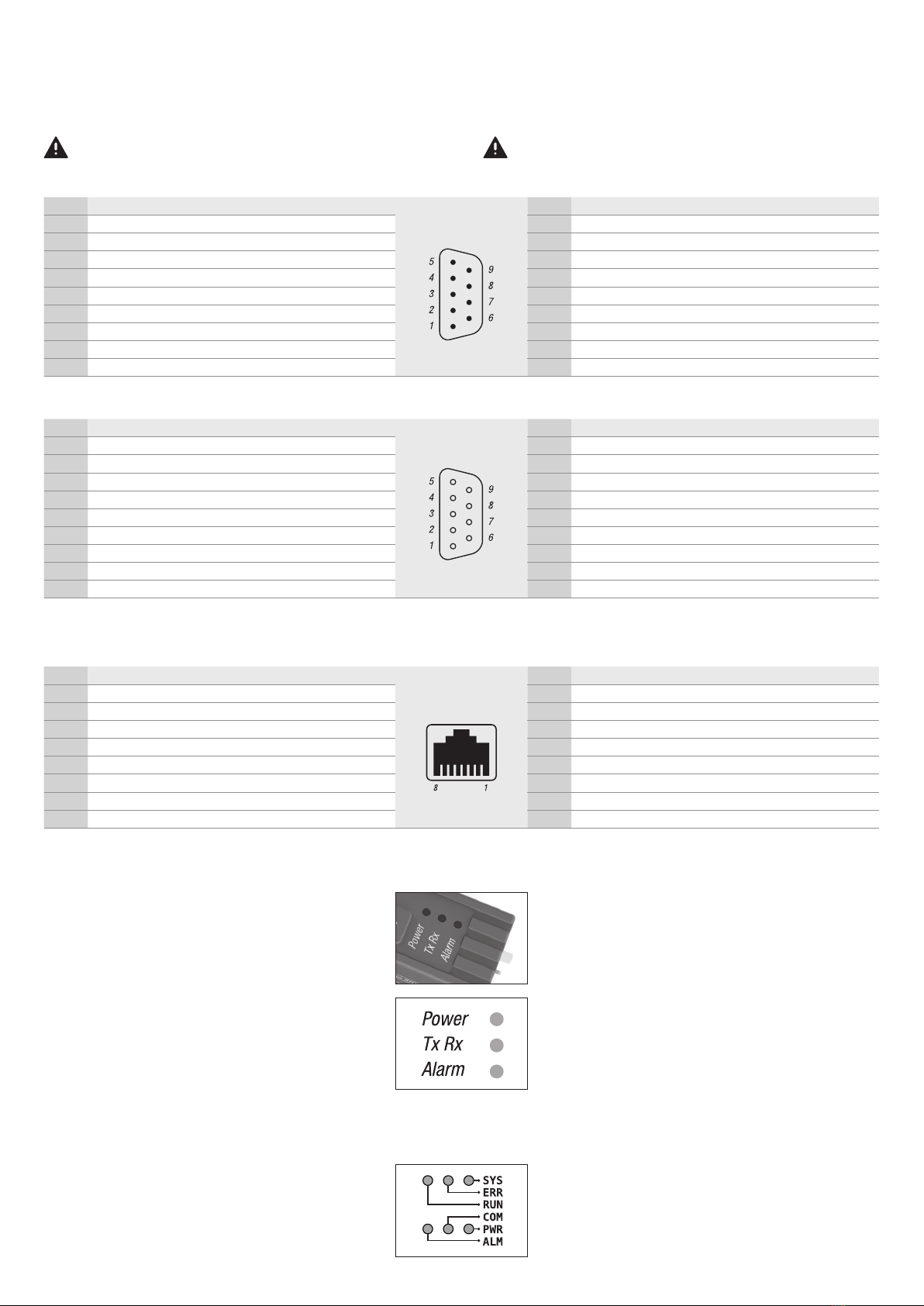
Pin assignment
All connection diagrams can be found in the operating instructions.
Please also refer to the additional operating manual «Digital
Communication»
Always disconnect the power supply before working on the
plugs!
LED operating status
Power
The green LED lights up when the unit is supplied with the
correct supply voltage and is ready for operation.
TxRx
The yellow LED flashes when the device is communicating
on the digital Modbus RTU interface.
Alarm
If the red LED flashes, there is a malfunction. If the LED is lit
continuously, there may be a serious problem. Disconnect
the supply voltage and reconnect the device. If the LED is
still lit, the unit must be returned for repair.
Note
The EtherCat/Profinet devices have an extended LED
operating status. Please refer to the operating instructions.
Steckerbelegung
Sämtliche Anschlusspläne finden Sie in der Bedienungsanleitung.
Beachten Sie auch die zusätzliche Bedienungsanleitung «Digitale
Kommunikation».
Bei Arbeiten an Steckern immer zuerst die Stromversorgung
trennen!
LED Betriebszustands-Anzeige
Power
Die grüne LED leuchtet, wenn das Gerät mit der korrekten
Speisespannung versorgt wird und betriebsbereit ist.
TxRx
Die gelbe LED blinkt, wenn das Gerät auf der digitalen
Modbus RTU-Schnittstelle kommuniziert.
Alarm
Blinkt die rote LED, liegt eine nicht schwerwiegende
Betriebs-Störung vor. Leuchtet die LED dauernd, besteht
eventuell ein schwerwiegender Fehler. Unterbrechen Sie
die Speisespannung und stecken Sie das Gerät wieder ein.
Falls danach die Alarm-LED noch immer leuchtet, muss das
Gerät zur Reparatur eingesandt werden.
Hinweis
Die EtherCat/Profinet Geräte verfügen über eine
erweiterte LED Betriebszustands-Anzeige. Bitte
konsultieren sie diesbezüglich die Bedienungsanleitung.
Sub D plug pin assignments Modbus RTU, power supply & analog signals (male) D-Sub Stecker Pinbelegung Modbus RTU, Stromversorgung & analoge Signale (male)
Pin Assignment Description Pin Belegung Beschreibung
1Common (-) GND analog signals 1Common (-) GND Analoge Signale
2Supply 0 Vdc 0 Vdc supply voltage 2Supply 0 Vdc 0 Vdc Speisespannung
3Supply +24 Vdc +24 Vdc supply voltage 3Supply +24 Vdc +24Vdc Speisespannung
4Output (+) Analog output, measured value 4Output (+) Analogausgang, Messwert
5Setpoint (+) Analog input, setpoint 5Setpoint (+) Analogeingang, Sollwert
6Tx+ RS-485 Output (Y) 6Tx+ RS-485 Ausgang (Y)
7Tx- RS-485 Output (Z) 7Tx- RS-485 Ausgang (Z)
8 Rx+ RS-485 Input (B) 8Rx+ RS-485 Eingang (B)
9Rx- RS-485 Input (A) 9Rx- RS-485 Eingang (A)
Sub D plug pin assignments Profibus (female) D-Sub Stecker Pinbelegung Profibus (female)
Pin Assignment Description Pin Belegung Beschreibung
1Not connected –1Nicht belegt –
2Not connected –2Nicht belegt –
3RxD/TxD-P Data transmit / receive; data wire B 3RxD/TxD-P Daten senden / empfangen; Datenader B
4CNTR-P Repeater control signal (RTS) 4CNTR-P Repeater Steuersignal (RTS)
5DGND Ground for data signals and VP 5DGND Masse für Datensignale und VP
6VP / +5V Power supply +5V 6VP / +5V Spannungsversorgung +5V
7Not connected –7Nicht belegt –
8RxD/TxD-N Data transmit / receive; data wire A 8RxD/TxD-N Daten senden / empfangen; Datenader A
9Not connected –9Nicht belegt gelb/grün
RJ45 socket pin assignments Profinet / EtherCAT (female) RJ45 Buchse Pinbelegung Profinet / EtherCAT (female)
Pin Assignment Wire color Pin Belegung Drahtfarbe
1Data (Tx+) yellow 1Data (Tx+) gelb
2Data (Tx-) orange 2Data (Tx-) orange
3Data (Rx+) white 3Data (Rx+) weiss
4Not connected –4Nicht belegt –
5Not connected –5Nicht belegt –
6Data (Rx-) blue 6Data (Rx-) blau
7Not connected –7Nicht belegt –
8Not connected –8Nicht belegt –

Default Factory Settings
Modbus RTU
Profibus (optional)
When using several devices simultaneously the user has to configure
each device with an individual address!
Profinet / EtherCAT (optional)
Further information on the device configuration can be found in the
operating manual.
Important notes
General information: Do not remove the electronics housing to
prevent damage to the unit. A damaged hologram seal will void the
warranty.
There are no serviceable parts inside the unit. Repairs must be
performed by qualified personnel only.
Installation: Do not use Teflon® tape or liquid sealing on the process
connections. Please ensure that the piping is clean and purged before
you connect the flow meter.
Your Vögtlin sales representative can help you to source suitable
O-rings, elastomeric seals, fittings and filters.
The used gas must be clean and dry.
As particle protection we recommend to install our 50µm filter at the
inlet.
It is recommended that the user check the devices on a regular
schedule to ensure that it is leak free as both metal and elastomeric
seals, gaskets, O-rings and valve seats may change with age,
exposure to process gas.
Mounting orientation and location: Please refer to the detailed
instructions in the operating manual.
Electrical connection: Please verify a proper electrical connection.
This device must be grounded. The supply voltage is 18..30 Vdc
(typically ±50 mV).
The current consumption depends on the instrument version. Please
refer to the information in the operating manual.
Toxic, flammable gases and ATEX: In the case of toxic and flammable
gases, the respective safety guidelines in each country must be
followed. The red-y smart devices are not approved for use in
Ex-zones. In the case of flammable and
toxic gases, fittings and pipes intended for that purpose must be
used. The responsibility for safe operation lies with the designer of the
facilities. The devices must not be used for explosive mixtures (ATEX,
detonating gas, consisting of O2and H2).
Please contact your sales partner if you have any question about the
product. Get the latest product information on:
www.voegtlin.com
Werkseinstellung
Modbus RTU
Profibus (optional)
Beim gleichzeitigen Einsatz von mehreren Geräten müssen vom
Anwender unterschiedliche Adressen eingestellt werden!
Profinet / EtherCAT (optional)
Weitere Informationen zur Gerätekonfiguration finden Sie in der
Bedienungsanleitung
Wichtige Hinweise
Allgemeine Hinweise: Belassen Sie die Abdeckhaube verschlossen,
um Beschädigungen am Gerät zu verhindern. Bei beschädigtem
Hologramm-Siegel erlischt die Garantie. Es befinden sich keine
zu wartenden Teile unter der Abdeckhaube Reparaturen sind
ausschliesslich von qualifiziertem Fachpersonal durchzuführen.
Installation: Verwenden Sie kein Teflon®-Abdichtband oder
Flüssigdichtmittel um die Anschlüsse abzudichten. Stellen Sie sicher,
dass die Anschlussleitungen gereinigt und gespült sind bevor Sie
das Gerät anschliessen. Ihr Vögtlin Vertriebspartner kann Sie bei der
Beschaffung von geeigneten O-Ring Verschraubungen und Filtern
unterstützen.
Das verwendete Gas muss sauber und trocken sein. Zum Schutz vor
Verunreinigungen empfehlen wir unseren 50µm Filter eingangsseitig zu
installieren.
Es wird empfohlen, die Geräte in regelmässigen Abständen auf
Dichtigkeit zu überprüfen, da sowohl Metall, als auch aus Elastomer
Dichtungen, Dichtringe, O-Ringe und Ventilsitze altern, bzw. sich
aufgrund der Prozessgaseinwirkung verändern können.
Einbaulage und Umgebungsbedingungen: Bitte beachten Sie die
ausführlichen Hinweise in der Bedienungsanleitung.
Speisung: Bitte beachten Sie den korrekten elektrischen Anschluss.
Dieses Gerät muss geerdet werden. Die Versorgungsspannung liegt
bei 18…30 Vdc (typisch ±50mV).
Die Stromaufnahme ist abhängig von der Geräteausführung. Bitte
beachten Sie die Informationen in der Bedienungsanleitung.
Toxische, brennbare Gase und ATEX: Bei toxischen und brennbaren
Gasen sind die Sicherheitsrichtlinien in den entsprechenden Ländern
zu beachten. Die red-y smart Geräte sind nicht für den Einsatz in
Ex-Zonen zugelassen. Bei brennbaren und toxischen Gasen sind
dafür geeignete Verschraubungen und Rohrleitungen einzusetzen.
Die Verantwortung für den sicheren Betrieb liegt beim Ersteller der
Anlagen. Die Geräte dürfen nicht für explosive Gemische eingesetzt
werden (z.B. Knallgas, bestehend aus O2und H2).
Bei Fragen zum Produkt kontaktieren Sie bitte Ihren Vertriebspartner.
Aktuelle Produktinformationen finden Sie unter:
www.voegtlin.com
Communication speed 9600 Baud
Data bits 8
Stop bits 2
Parity None
Node address 247
Node address 125
Übertragungsgeschwindigkeit 9600 Baud
Datenbits 8
Stoppbits 2
Parität Keine
Node-Adresse 247
Node-Adresse 125
Name Red-y-for-gasflow
IP address 0.0.0.0
Name Red-y-for-gasflow
IP Adresse 0.0.0.0
Other manuals for red-y smart Series
1
Popular Industrial Equipment manuals by other brands


MULTIQUIP
MULTIQUIP Whiteman series Operation and parts manual

Nextron
Nextron LPM3 manual

Speedline Technologies
Speedline Technologies ELECTROVERT Aquastorm Options guide

Schmidt & Bender
Schmidt & Bender MTC LT manual

Rittal
Rittal SK 3209. Series Assembly and operating instructions

TNA
TNA TX7302 Installation and operation manual