Nextron LPM3 User manual
1
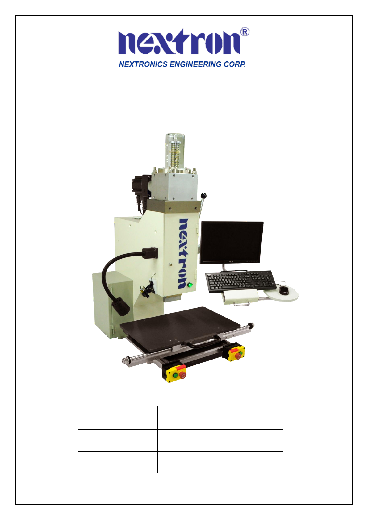
LPM3 Manual
Company
:
Nextronics
Date
:
2018/04/16
Version
:
LPM3-A0

2
INDEX
1. Introduction
1.1. Safety
1.2. Installation
1.3. Specification
4
4
5
7
2. Machine Features
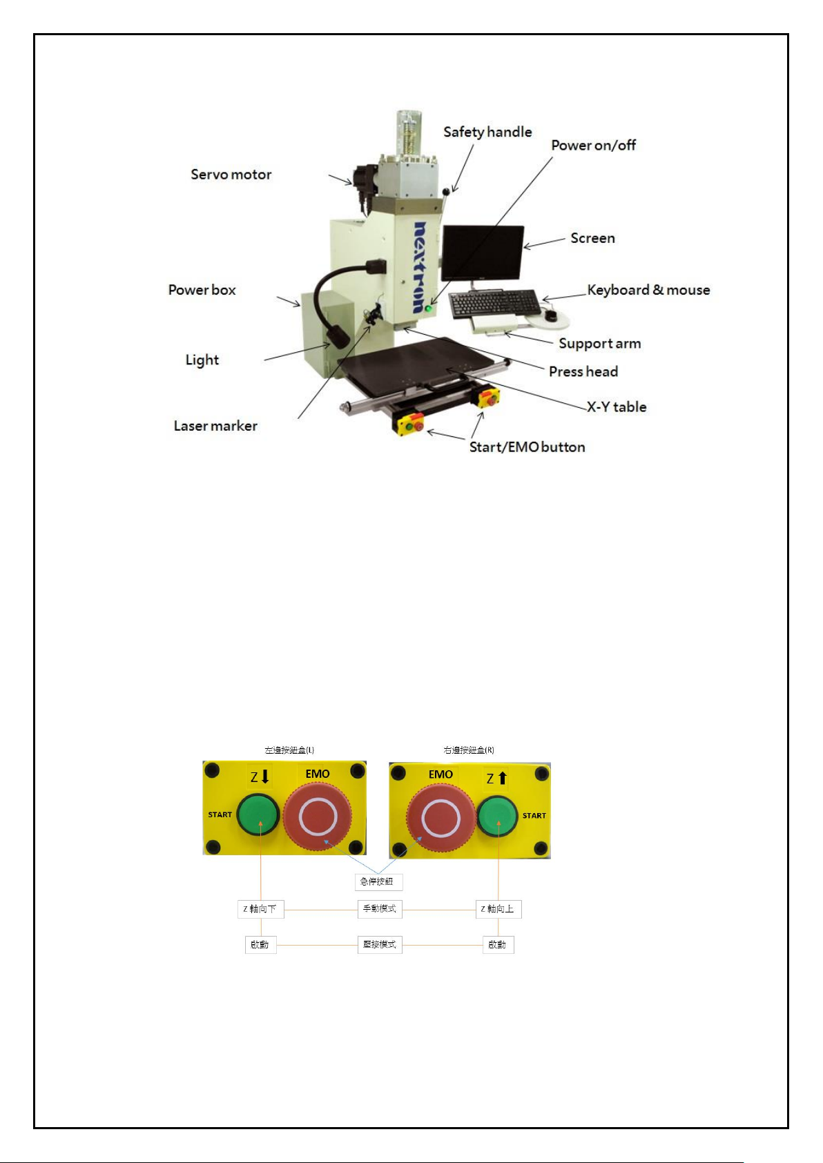
2.1. Machine configuration
2.2. Function
8
8
9
3. Operating
Instruction
3.1. Power on
3.2. Operating confirmation
3.3. Before-production confirmation
3.4. In-production confirmation
3.5. After-production confirmation
10
10
11
11
11
11
4. Software
Operation Interface
4.1. User interface introduction
4.2. User change
4.3. Password setup
4.4. Load recipe
4.5. Operation
4.6. Continue press
4.7. Edit recipe
4.8. Process log
4.9. SPC
4.10. Parameter setup
12
12~13
14
14
15
16~19
19~22
23
26
28
30
5. Maintenance
31
6. Appendix
6.1. Tool and accessory
6.2. Machine table size
6.3. Contact information
32
33
34
35

3
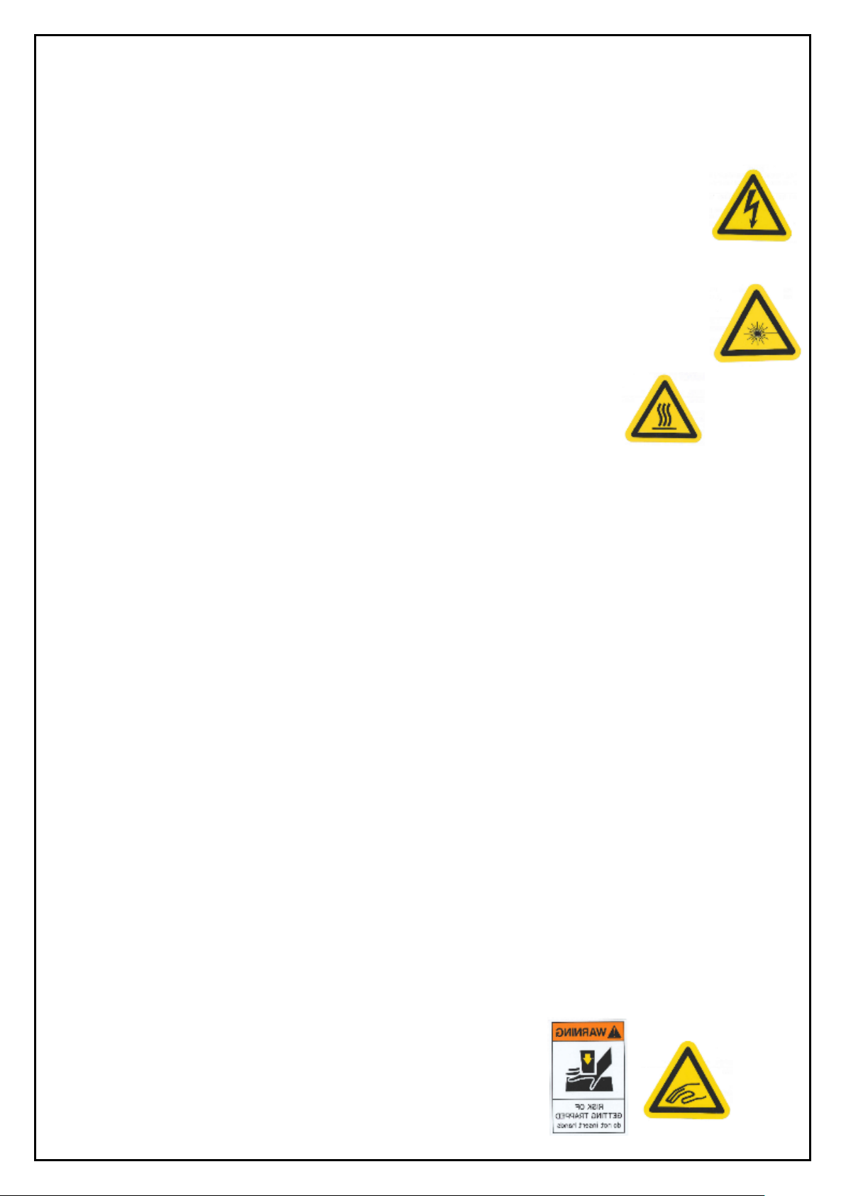
Safety precautions to avoid injury
The safety measures designed by this equipment prevent operators and maintenance personnel from being
harmed during the operation of the machine.
The most important thing is operator or maintenance personnel must configure specific safety precautions to
avoid injury. In the same time, the equipment also needs specific safety precautions.
In the best condition, the equipment must be in a clean, dust-free environment. Do not operate the device in a
wet or hazardous environment.
Before operating the device and during the operation of the device, pay attention to the following safety
precautions:
1. Always wear approved eye protection when operating the equipment.
2. Always ground the power supply properly to prevent electric shock.
3. Always maintain proper power connection to prevent danger.
4. When performing equipment maintenance, make sure to turn off the power switch and disconnect the power
cord from the power supply always.
5. Do not wear loose clothing or jewelry that may get caught in moving parts of the device.
6. Do not place your hands on the bottom of the press head while the equipment is in operation.
7. Do not change, modify or improperly use the equipment.
8. Do not use the device incorrectly. This device is used to press the connector into the circuit board. It will
cause people to get hurt in an attempt to use this device for stamping, squeezing, bending, or rolling other
products.
9. Do not use the optional work light and laser positioning marker to irradiate eyes.
4
1. Introduction
This manual contains procedures for installation, safety, operation, and maintenance of a 5-ton desktop servo press-fit
machine LPM3.
1.1. Safety
1. Electrical-
The power wiring of three-core cable connected to the power box needs to include a grounding
wire to prevent leakage currents from affecting people. The cross-sectional area of this single core
must be greater than 3.5mm². A fixed retaining ring is installed on the main power box and
the distribution box door to prevent personnel from the danger of electric shock.
2. Protection of eyes and ears-
Operator should wear eye protect when operating or maintaining the machine. The noise generated
by the machine is not excessive over 70 dB. It is based on your own discretion to wear ear
protection or not. And please be careful not to look directly at the laser marking instrument.
3. Temperature-
Please do not touch the motor which may generate high temp. 30~50°C.
4. EMO, Emergency Off buttons-
The emergency off button is installed on both sides of the front of the table and is clearly marked. When they were
pressed, you must pull out of the button to release from the lock state. The EMO loop is a hard interlocked
connection that is only released when the EMO buttons are released. The motor's control circuit is cut off when the
EMO buttons are pressed. After all safety and conditions are met then EMO activation signal is output from the
computer.
1) The Acroloop servo controller watchdog signal is true and is false when the controller detects a problem.
2) The Acroloop servo controller PLC output - servo controller has an internal program to monitor servo operation
and disconnect the EMO circuit when a problem is detected.
3) Motor overload relay, which is a temperature-sensitive motor overload protection device, monitors the motor
over-current condition. If the motor current is consumed for a long time, it will automatically cut off and
re-conduct after about 3 minutes of cooling.
5. Release emergency operation-
After confirming the emergency stop condition and eliminating it, release it under the safe condition, pull up the
emergency off button and start the motor power.
6. Two-handed start switch-
The two-handed start switch is located on the left and right sides of the button box in front of the XY-TABLE.
The button is a flat button with no protrusion. In order to prevent body or other inadvertent contact, each switch
is separately connected, and the two switches must be pressed at the same time to start the machine operation.
7. Safety handle-
The safety handle is placed on the upper right side of the machine. When the handle is pressed down, the machine
can be started with the two-hand button. Please push the handle up when replacing the fixture. The operating space
can be increased for safety concern. During the pressing process, when the equipment is down and someone is in
danger, please push back the handle for emergency stop. In case of power failure, the product under the pressing
head can also be taken out.
8. Safety cover-
All covers must be positioned before pressing, including front and rear
panels, top screw cover and other protective parts.
5
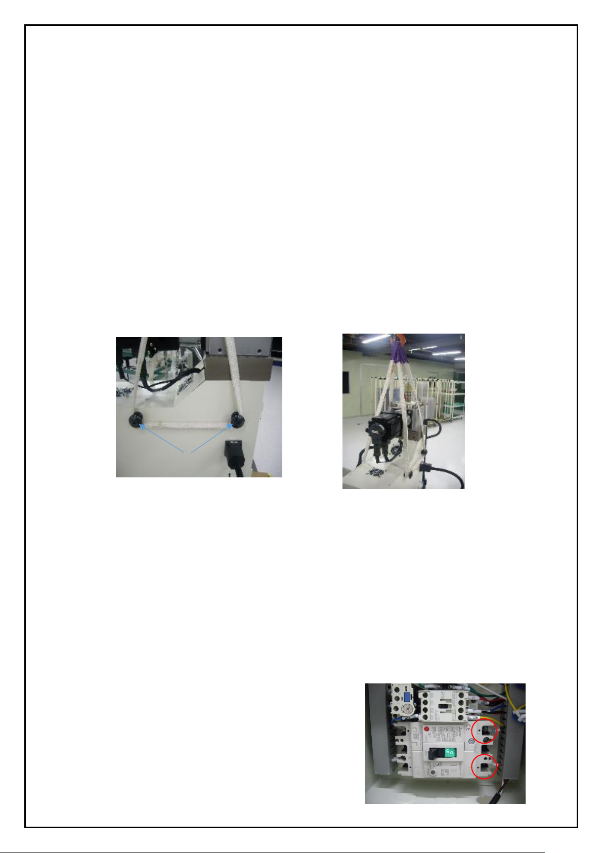
Hanging bolts
1.2. Installation
This section describes the installation steps and requirements.
1. Notices before the installation-
1) Personnel protection requires a safety helmet and work gloves.
2) Set the security scope of the unpacking and hanging area. Except the relevant staff, other personnel are prohibited
from entering.
3) License is needed to operate the relevant cranes or stacker.
4) Check if the hanger bolts are locked and the safety of hanging equipment such as slings.
2. Unpacking the box-
The press-fit machine and other separated parts are all packed in plastic film, and sea or air packing box plus
aluminum foil blister packaging to protect it. Please remove foil pouch or film wrap (except for X-Y Table and
screen bracket's fixed film) and take out the other separated parts.
3. Hanging operation-
Firstly take off the force plate of the fixed base, and hang the sling over the hanging bolts on both sides of the
upper part of the device (below). Take care not to touch the motor with the slings or other parts. Then use a crane or
forklift to lift the press-fit machine away from the load-bearing plate, lift and place it on the work table.
Make sure that the placement table must be leveled and pay attention to the location of the keyhole.
4. Lock and adjust the machine-
1) The mounting hole size of the device is 310mm*450mm, and the mounting hole diameter is 13mm*4 holes.
2) When the equipment is hung and placed 50~100mm away from the desktop, stop first, then insert the attachment
bolt size M12-60Lmm*4pcs. Then slowly lower the bolts while guiding the counter mounting holes in the table.
3) Place the washer and nut under the table from the underside of the bolt and secure it with a movable wrench.
There are 4 seats in the machine seat.
4) Place a horizontal device on the X-Y Table and rotate the tripod of the table to adjust the level of the X/Y axis.
5. Power-
1) The equipment uses 220V AC 1ψ 15Amp single-phase AC.
2) Connect the power box to the power cable of the device beforehand. The cable specification is three-wire
220V AC 1ψ15Amp.
3) Make sure the power supply box is powered off.
4) The no-fuse switch in the device power box is OFF (left).
5) Make sure the power on the front panel of the device is
turned OFF.
6) Make sure the power supply and equipment grounding
Protection are ready.
Connection point of power cable

6
6. Connecting the wire-
1) Pass the power cable through the hole in the lower part of the power box of the device and strip it to lock the
switch contact (above).
2) Turn on the power and measure the input of the power end of the device with an electric meter. Check if there are
any power and power specifications.
3) Connect the barcode scanner (optional), insert the scanner USB connector to the front of the unit, and the
X-Y Table USB socket below the table.
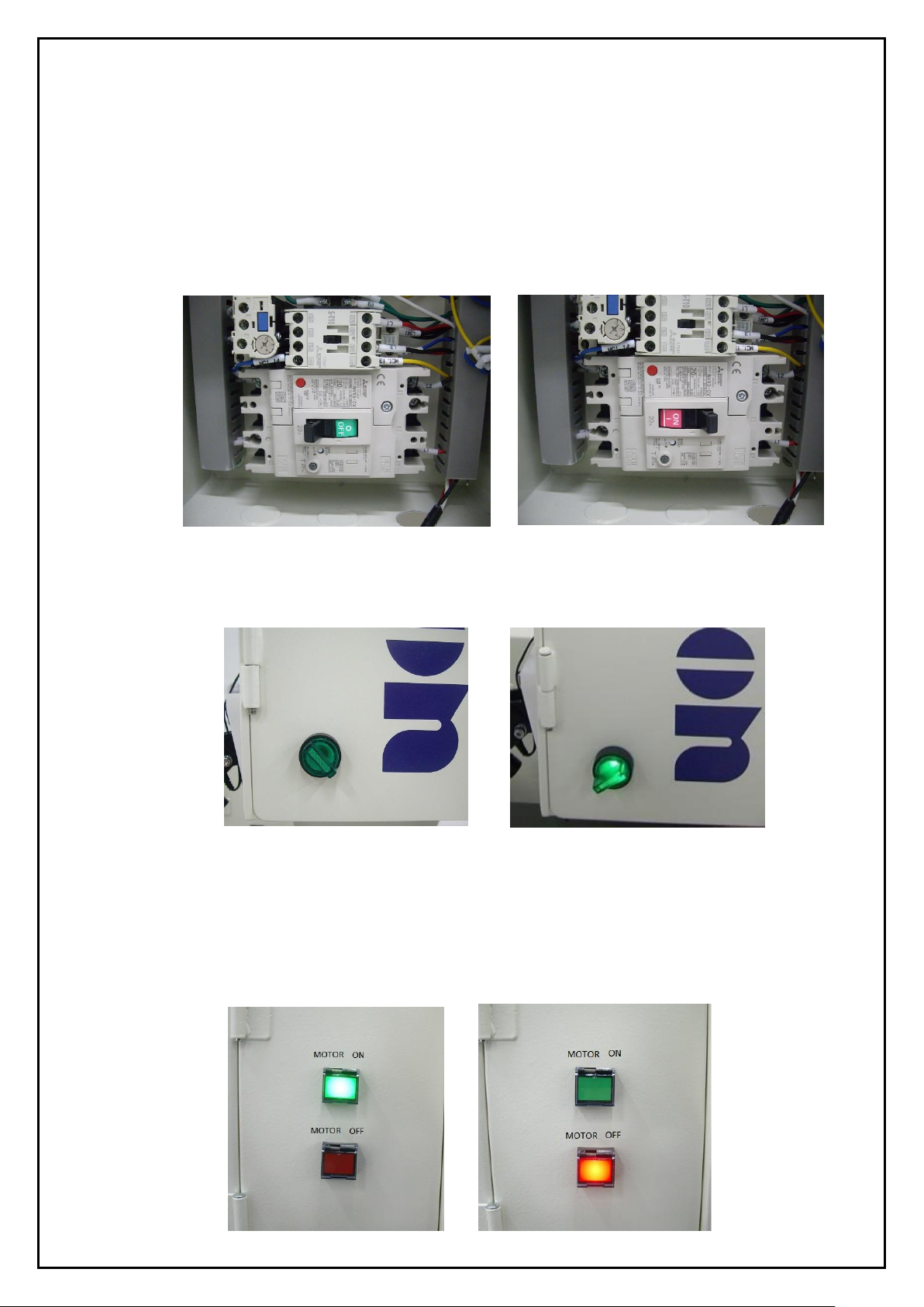
7. Turn on the machine-
1) Turn on the power switch in the power box to the ON position (see the left picture below).
2) Open the main power switch of the front panel, and the power light will be on to start the machine and confirm
that the computer is started (below right picture).
3) Press the green light button on the left side of the box to start the motor (lower figure below).
4) The computer will automatically enter the login screen or click on the replacement operator (screen function key),
default user account and password for "1". The administrator can change the initial login account and
password "1" to "Administrator" or the user can define your own account and password.
Note : Please remove the power before hanging the equipment, and fix the X-Y Table and screen bracket with
protection before the hanging operation.
POWER
OFF
ON
7
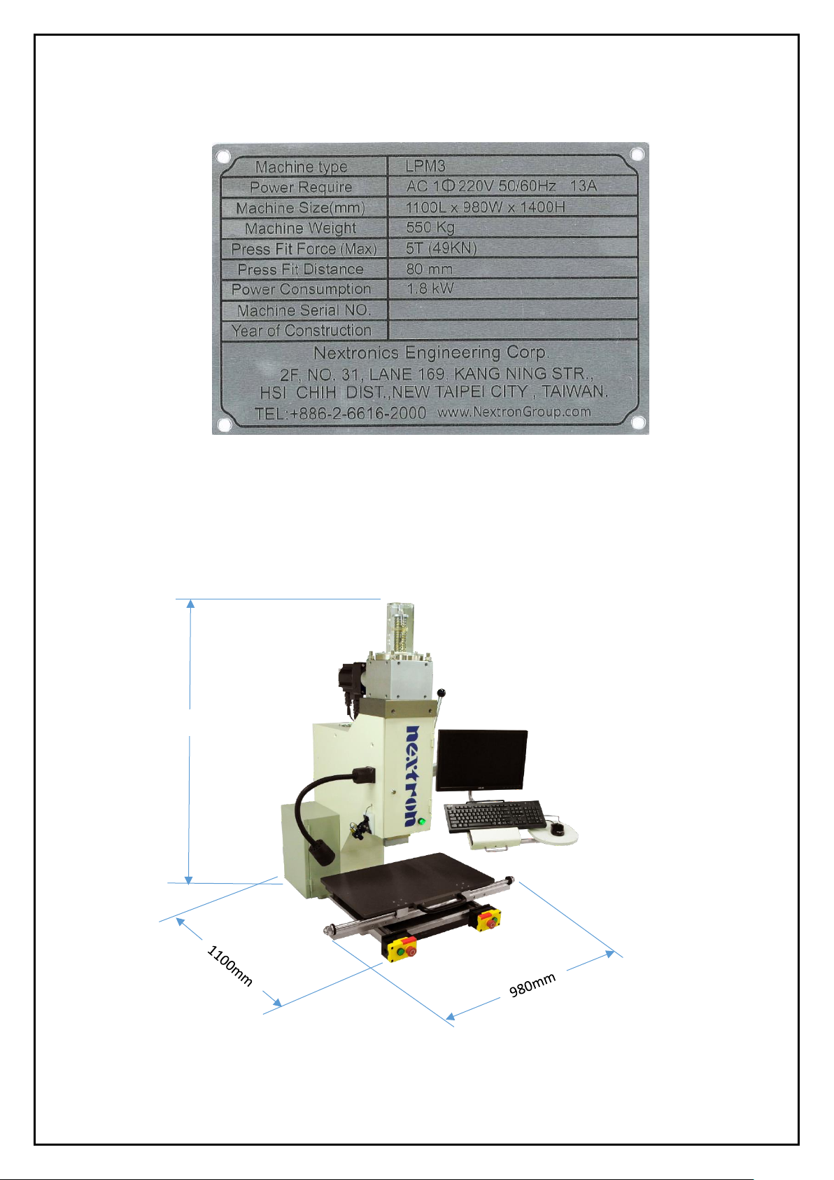
1.3. Machine specification label
1. Machine type, power require and weight information are labelled on the back panel of the machine.
2. Power supply: 220V AC single phase
Weight: 550 kg
Press-fit force: 5000 kg
Press-fit distance: 80mm
Machine size: 1100L x 980W x 1400H ±50mm
3. End of life cycle-
It is suggested returning the machine to Nextronics after end of life.
1400mm
8
2. Machine Feature
This section introduces the use, capabilities, and configuration of the LPM3 tabletop servo press-fit machine.
2.1. Machine configuration
1. C-type structure with three sides open active desktop.
2. Easily move jigs and objects to be pressed with X-Y Table.
3. In addition to the text, the light ON/OFF makes it easier to identify.
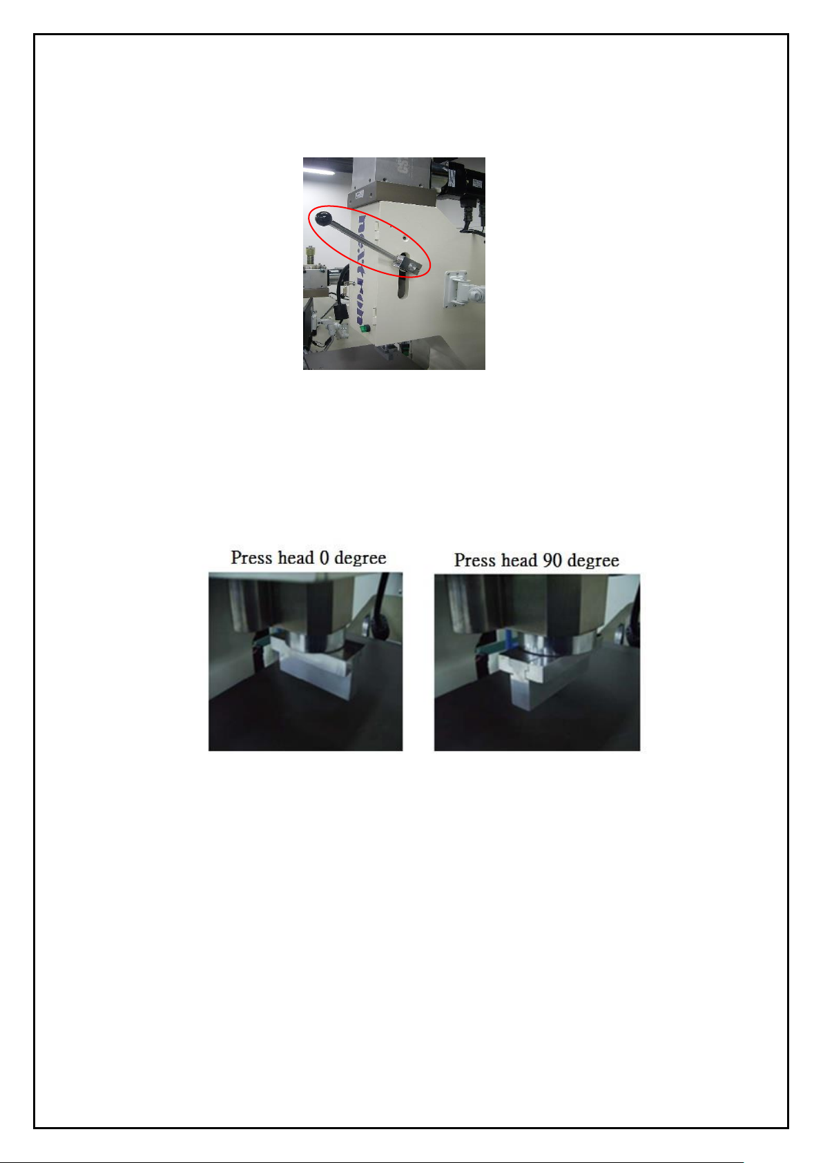
4. The press head can be turned 90 degrees to match the direction and size of the connector.
5. Button box-
1) Emergency off button (EMO) - Use for emergency stop.
2) Z axis control button - In the manual mode, the left button controls the Z axis down and the right button controls
the Z axis up.
3) Start button - In both press-fit mode and recipe mode, both hands press simultaneously to start the job.
6. Safety handle - Increase space and protection when replacing product fixtures.
7. Work Lights (Optional) - Provides lighting to minor working conditions.
8. Laser cross-marker (optional) - Assists positioning and marking of objects.
9. Safety cover (optional) - Personnel safety protection.
10. Barcode scanner (optional) - for backplane serial number input.

9
2.2. Function
The LPM3 servo press-fit machine is designed to meet the increasing demand for quality control of press-fit
connectors on today's PCBs. As industry changes, increased connector density makes the connector structure
more vulnerable and the PCB becomes more complex and expensive and easy to damage, thus making the
process of backboard assembly more sophisticated.
LPM3 servo press-fit machine data can provide valuable analysis to improve the entire press-fit process
technology. It also improves the efficiency of the press-fit process because the traditional manual press-fit
connector technology is very sensitive to labor and unstable. The production volume, quality and efficiency
depend on the operator inevitably. However the use of servo press can bring feedback of quality data and more
stable PC control technology to improve production quality and efficiency.
1. Manufacturing capability-
The LPM3 can provide up to 5 tons (49,000 N) of force on the press head. The Z-axis travel is 80mm. With the
standard 50mm press head, the X-Y Table surface space is up to 100mm from the upper position of press head.
The upper space through the programming before the press-fit can achieve any desired work gap. This feature
increases productivity by limiting the distance during each cycle. Press head can be replaced with different
height specifications depending on the processing requirements. Distance accuracy is 0.04mm, travel repeat
accuracy is 0.02mm,
The speed control range is 0.01~13mm/s, and the press-fit process can be operated at a variable speed so that
the force connection can be set variously depending on the situation.
2. Press-fit process control-
The force and distance control can be precise and cross-protected so that the press-fit process can be effectively
monitored.
1) Set the upper and lower limits of the standard force so that it corresponds to the range of variation due to the
variables of the pins and the PCB. Exceeding the upper limit of the monitoring force may damage or cause
abnormal set point protection, and the lower force limit is overvoltage into the PCB force detection, to
prevent abnormal factors, and then the reaction connector and PCB retention is insufficient, resulting in the
connector is detached during use.
2) Press-fit settings control the travel. When the force is normal enough within the interval, the connector can be
pressed to the programmed settings. At a certain distance on the surface of the board, the press monitoring
feedback is performed at a fixed distance. The hybrid technology controlled by servo-controlled press-fit
head and robust press-fit mechanisms ensures press precision of the connector to a higher requirement on
accurate press stroke. This data can be completed by manual adjustment and provided processing sequence.
The standard board size is limited to 450mm x 600mm. The press-fit structure is an open space and the vehicle
can be steered and placed. The use of large press-fit circuit board dimensions is 500mm x 700mm.
Press-fit recipe editing is the setting of profiles and tables for the connector type and press position. Each press
cycle is called a press program that passes the setter's position on force, speed, and connector during the
press-fit process. This highly flexible technology allows practically unlimited press-fit option changes to meet
current and future connector needs. Press-fit recipe edits to describe the connector, tool, PCB and press-fit
program data can be stored in an offline or online database.
10
3. Operation Instruction
3.1. Power on
It is important to ensure that all safety settings are in place before power on, and that personnel maintain a
distance from the machine before starting the machine.
1. Power switch-
1) The main power supply external input switch is located in the left side of the machine. Turn the switch to the
OFF position (left pic.) for all input power. This switch is used to switch on after installation. It is not to be
turned off. Turn it to the ON position to input power supply, but please switch it to OFF when you want to
move, repair the machine or stop for a long time about 1 week or more (right pic.).
2) The power switch is located on the lower left corner of the front panel. Turning to the OFF position will
disconnect all system power source. Turn the knob to the ON position to start the machine, the knob lights up
(below pic.).
3) The motor start switch (lower left) is located on the left side of the box with green cover button. The button
lights up and start the motor after pressing it. It must be started when restarting the device each time. When
using an emergency stop switch or a motor abnormality causing a stop, the lower red cover button will light up.
After the emergency stop switch resets and the motor abnormality is removed, press the green cover button to
start. The red cover button will light out.
The motor shut off switch (lower right) is located on the left side of the box with red cover button, press it to
turn off the moto.
POWER
ON
OFF
POWER
ON
OFF
11
3.2. Operating confirmation
1. Make sure that the emergency stop switch is released.
2. Make sure that the safety handle is pulled down to the lower positioning point (below).
3. Make sure that the zero calibration job is complete.
3.3. Before-production confirmation
1. Check if the safety handle is lowered.
2. Confirm the product recipe is loaded, loading completion and correctness.
3. Confirm whether the upper and lower tools are used.
4. Confirm the direction of the press head is 0 degrees or 90 degrees (below).
5. Confirm the operator
3.4. In-production confirmation
1. Serial number input
2. Press position
3. The connector corresponds to the upper tool
4. Connector pre-insertion holes in place without tilting
5. The tool is placed and fitting the connector
6. Condition after press-fit is completed
3.5. After-production confirmation
1. Load recipe reset
2. Pull the safety handle to the upper position
If there is any abnormality happened, please ask the equipment personnel for assistance.
12
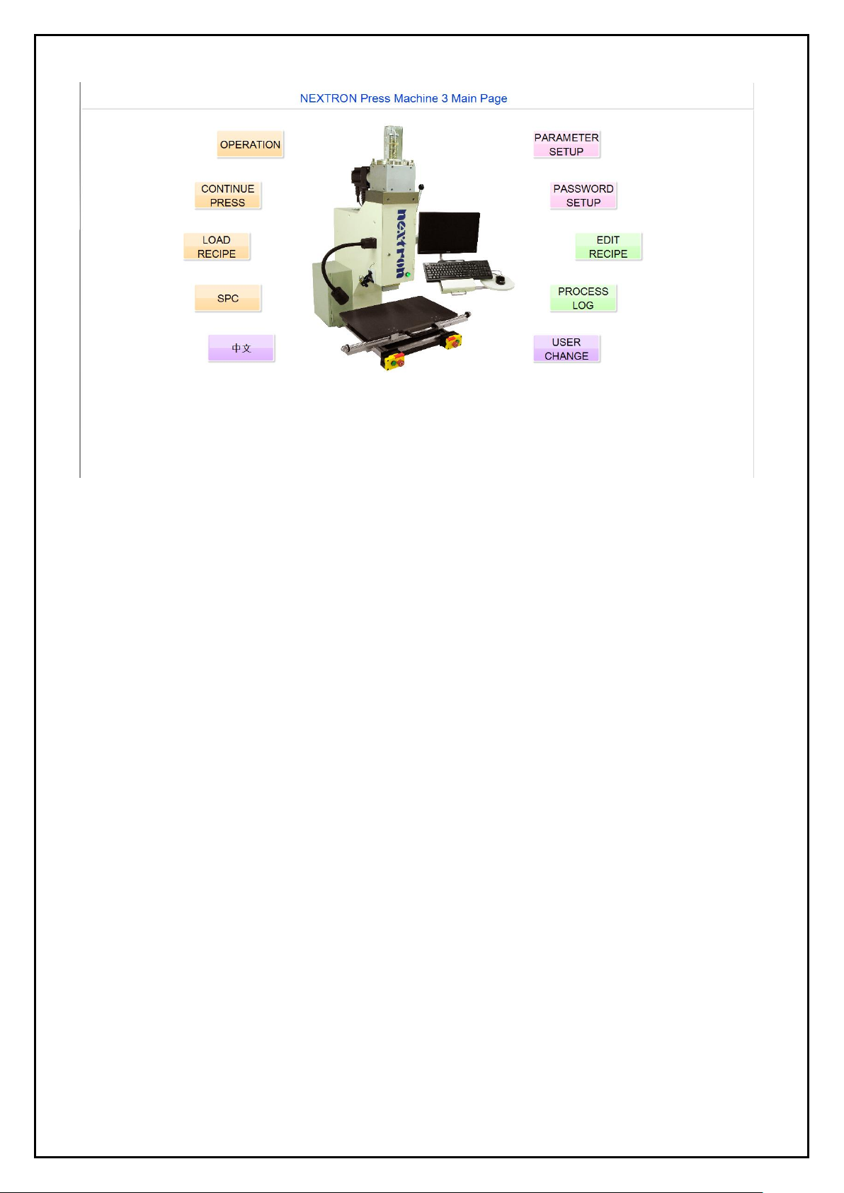
4. Software Operation Interface
4.1. User interface introduction
1. Operation-
Force, distance, analysis curve, press position diagram, product data of the pressing process during production
operations, production schedule and other data, production status monitoring, automatic storage and query of
force curve. In addition, various error indications are linked to the operating instructions to assist in
troubleshooting.
2. Continue Press-
Instantly run setup on a single press force, distance and speed to start sample pressing rapidly. Jig test and initial
press force, accurate distance and speed data confirmation, establish correct data and data immediately.
Create, check, and modify connector data to input and output press parameters directly to the connector database.
It can perform the job of the segmented press, and provide the relevant pressing parameters that have been
confirmed to be directly imported into the connector database. It can assist recipe editing at the same time, and load
the completed parameter data to recipe edit instantly.
Note: This function is not suitable for work order production, this process does not record the press data and curve.
3. Load Recipe-
The production call corresponds to the lot number of the backplane, and the completed pressing program will be
established to call, load, and perform the functions. The production SOPs have graphs and tabular displays. It
can confirm the connector part number, press position, the jigs and procedures and there is a mechanism for
preventing lapses. It is mandatory to write the serial number of the lot number before it can be loaded for
identification and traceability of production records.
4. SPC-
The statistics of the production yield of the production lot number and the product item number section can also
be used in conjunction with the yield statistics for the pressing position. In addition, SPC control statistics are
applied to the connector press force parameters. The data can be exported in .CSV format.
5. Chinese/English switch-
It provides Chinese and English OS environment.

13
6. Parameter Setup-
This is to set the storage path of the press recipe, drawings, statistics, graphs, and production records. The safety
settings can be used to set the press force, time, standby point traversing value, PCB, connector. When the
machine is set up, it is effectively protected against damage.
7. Password Setup-
This is to create, modify and delete the authority. It can set permissions of user based on the operator's job function.
8. Edit Recipe-
Set up a pressing program including force, stroke, sequence, connectors, product photos, and other related data.
The program allows the production to perform continuous operation functions in accordance with the settings, and it
can also be quickly edited with the continuous pressing function.
9. Process Log-
The data generated in the production, the actual press force, distance, corresponding product number, lot number,
operator, time, pressing position and status are recorded. Data can be searched and translated to Excel files.
10. User Change-
In addition to the initial start-up settings, it can also change the operators for tracing on quality.
4.2. User change
A login window will appear on the screen displays for user interface. Only the "User change" option can be used
in this state. Enter the user name and password in the window, and then press Enter to enter the user interface.
The user can use the function according to the permissions. The functions that can use permissions will display
bold characters, and those without permissions will appear gray characters. In the production schedule, the
operator will be replaced, and the replacement operator will be registered according to the function "User change".
The page is as follows.
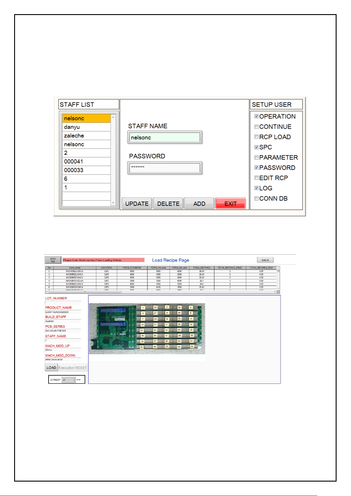
4.3. Password setup
There are 7 options for the use of permissions, click the option according to the required permissions. If you want
to create a new user, you must first use a legal administrator level login to set up. User and password are limited
to 10 bits max. and with case sensitive.
1. There are 3 display blocks in the password edit display-
1) All user names
2) Add user and password settings
3) Permission check
2. Password editing settings-
1) Press the update button for modification
2) Press add button for new input
3) Press delete button to delete data
14
3. Permission description-
The permission item is related to the limitation of each function box on the homepage except the last one
“Connector database” refers to the connector setting function and continuous pressing function in the edit
recipe.
Add - Create user name and password information, check the permission item, and press Add to add the user.
Update - Click to modify the user name, click to edit the permission item, and then press Update to modify the
user permissions.
Delete - Click to delete the user name, then click Delete to delete the user.
4.4. Load recipe
Selection, confirmation and execution of the pressing process for production.
1. Status columns - Shows the status of the program as Load, Execute, Wait, Error status.
2. Open file - Click on OPEN FILE key to selectt the recipe file for the backplane product that has been created.
The part number field displays the name of the open file. After the recipe file is opened, all the data will be
displayed in the column table. When the LOAD key is reversed black, the lot number is entered again.
Note - Lot number must be entered. It can be used in follow-up quality tracking records.
15
3. Data display column - After confirming the call recipe file, the part number, creator, top press head fixture, bottom
bearing fixture and PCB number will be displayed.
4. Parameter display table - After the recipe file is confirmed, the parameter values and corresponding press fixture
numbers are displayed for each item set on the backplane.
5. Press position area - Shows the backplane image and press sequence.
6. Load key - The operator confirms whether the fixture, BOM, contents of lot number are in accordance with
operating system. Enter the lot number before loading.
7. Execution key - After confirming the page content, click Execution key. When the execution is successful, the font
will be highlighted, and click Back to the top page when completed. Enter the operation screen, after the successful
loading, you can use the data of the editing of the recipe table to produce.
Note - After the execution key is pressed, in order to ensure the accuracy of the press distance, it is confirmed that
the origin calibration will be performed synchronously during the execution. The personnel shall pause the work
before the calibration is done.
8. Reset key - Reset of the product must first be performed, the original recipe must be deleted, the page field data
should be cleared, the recipe can be changed or the continuous pressing function can be used.
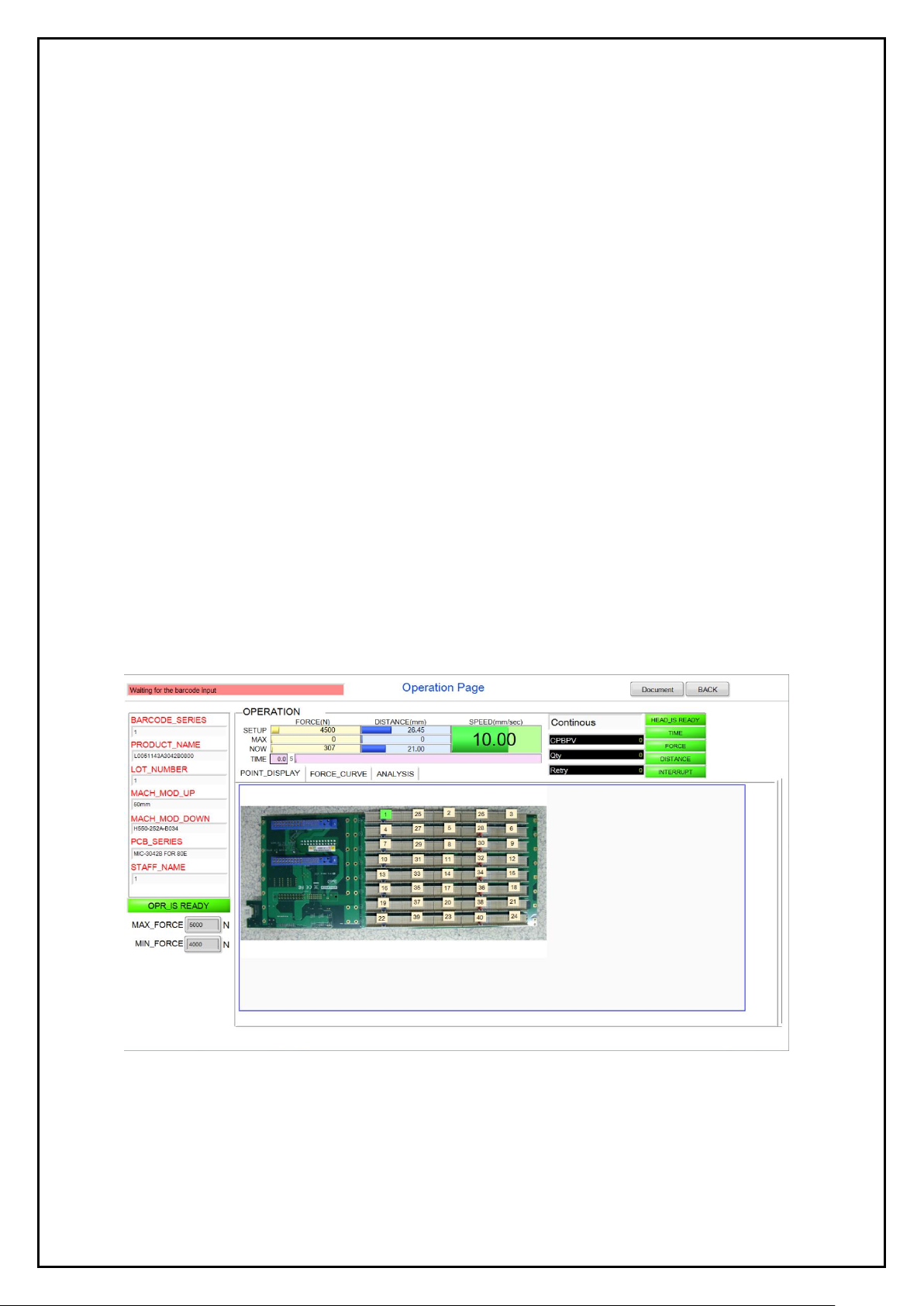
4.5. Operation
After loading the backplane recipe, enter the operation screen for production operation, the production operation
page displays the pressing position, setting value, feedback value, use the photo to make the position of the
pressing connector. It helps operator to better understand the connector and its position and the production
process data.
1. Machine status column - Shows the current status of the machine
2. Force display column - Shows set force and maximum force and current force (unit: N)
3. Distance display column - Shows the setting distance and maximum distance and current distance (unit: mm)
4. Speed display column - Shows the setting of the press speed (unit: mm/sec)
16
5. Time display column - Shows the instant action time of pressing (unit: sec)
6. Pressing quantity data display column -
CPBPV - The total press points on the backplane
Q'ty-Shows the number of completed PCB board
Number of repeat - Shows the number of repeat press points
7. Abnormal item -
1) Press head status column -
If the safety handle is not pulled down, the press head does not drop to the red display (means the press head
does not reach the position). After the safety handle is pulled, the position is changed to the green display
(means the press head has been positioned).
2) Original point return (OPR) status display -
During the production by the recipe, the press head will force the OPR and confirm the accuracy of the distance
setting. However, the OPR will not be performed if the safety handle is not pulled to allow the press head to be
positioned. Therefore, if the calibration is not performed, the field is red (OPR calibration is not completed), the
OPR calibration operation is completed, and the field is displayed in green (OPR calibration has been
completed).
Note - Although the speed is slow when performing OPR calibration, please keep people away from the
machine to prevent injuries.
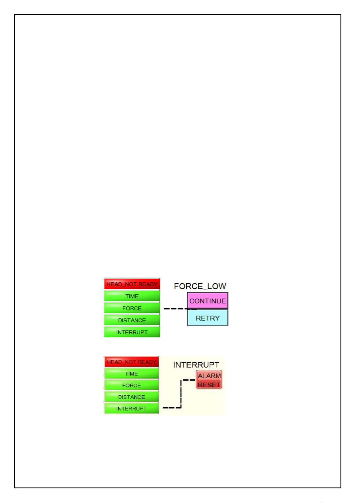
3) Abnormal item column -
When an abnormality occurs, it corresponds to the abnormal item column, and abnormal statuses such as "time",
"stress", and "distance" are displayed as red abnormalities. The pressing parameter message stays at the current
pressing sequence number. After confirming the status of the press, and selecting the abnormality, select one of
the following steps (continued or repeated) for subsequent operations.
1) “Continue”- Perform the next pressing procedure.
2) “Retry”- Repeat the current procedure.
If the abnormal item is "Interrupt", it will be displayed as a red abnormal state, but its exception handling
block is "ALARM RESET", and it must be eliminated to release the procedures.
4) The reset steps of various work interrupt -
1) The press head is not in its position - Pull the safety handle to the lower positioning point and press ALARM
RESET again.
2) The safety sensor is triggered - Eliminate the cause and press ALARM RESET again.
3) The servo upper and lower limits are triggered - In manual mode, press to rise the Z axis (lower limit trigger)
or lower the Z axis (upper limit trigger) to make the press head away from the limit sensor to eliminate the

17
triggering factor. Press ALARM RESET to cancel the warning and perform the OPR calibration operation.
The recipe operation needs to be loaded again.
4) EMO button is triggered - After confirming that the safety condition has been eliminated, pull the EMO button
and press the motor power on. If you need to move the press head out of the current position, press the Z
button to move it. Press ALARM RESET to eliminate the warning and performs a OPR calibration operation.
The recipe operation needs to be loaded again.
5) Analysis of abnormal item -
1) The press head is not positioned - the safety handle has not been pulled down or the trigger switch has
malfunctioned.
2) Work overtime - Error in parameter setting of press parts, resulting in overtime of work time or setting
of work time parameters too small.
3) Force error - actual force exceeds lower force limit.
* PCB hole is too large
* Connector specification error
* The setting range of the lower limit value is too small
4) Force error - actual force exceeds upper force limit.
* PCB hole is too small
* The setting range of the upper limit value is too small
* Pin bending deformation did not lead into the hole
* Distance parameter error
* Connector specification error
* Jig error
5) Distance error - Generally occurs when the force value is greater than the upper limit value.
6) Work interrupt - Other factors cause the sensor to be triggered to stop the job
* Push back the safety handle during operation
* The emergency stop button is triggered
* Servo up and down limit sensors are triggered during operation
* Safety sensor is triggered
8. Press product data display column -
Display the product serial number, product name, part number, lot number, and PCB number that are now pressed.
The product serial number is loaded or entered by the scanner after the barcode is loaded or entered. Each time a
PCB is completed, the column will be cleared. If no bar code is scanned, the job cannot be executed (the bar code
check function is checked on the parameter setting page).
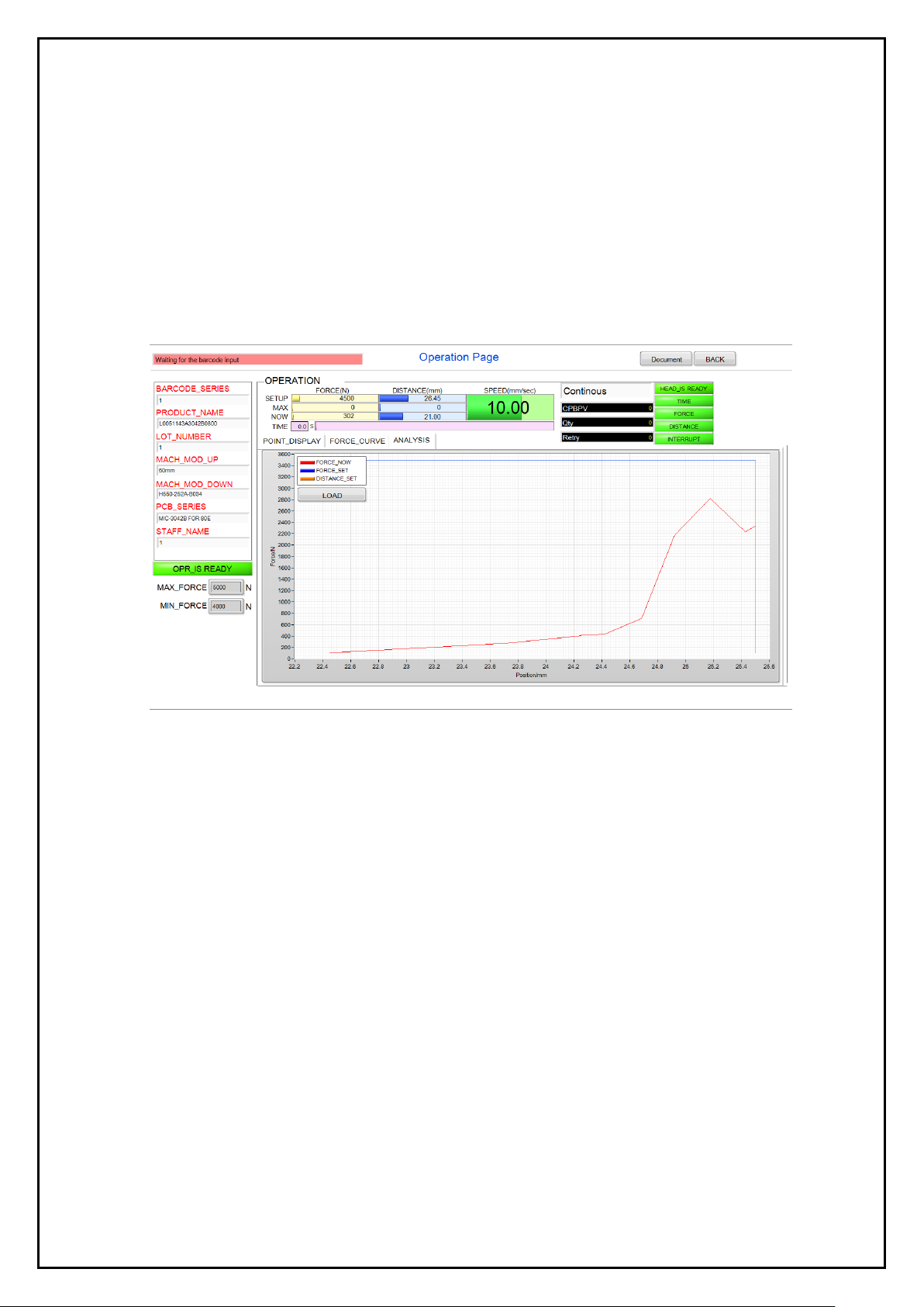
9. Curve display column - Shows actual force and distance being press.
1) Chart description -
* Orange - Distance setting
* Blue - Force limit setting
* Red - Force and distance correspond to the actual value
* Y-axis - Force (N)
* X-axis - Distance (mm)
2) Curve description -
When the press head is pressed, there will produce a force-distance composition of a red curve, starting from
the lower left corner of the graph 0 points. With the distance increases, the force enter the PCB with the eye
of needle, resulting in curve rise and fall changes. The distance to the end of the limit the line stops and
returns to complete the pressing operation.
18
The press curve of the same connector will be different with the roughness of the surface of the plating layer
in the terminal and PCB hole. During the pressing process, the force rises above the force upper limit is
abnormal. The operation will also be stopped and a warning message will be sent out.
3) Save key -
Use this key to store separately and set the path and file name in the continuous press test curve. In the
recipe press mode, the graph should be manually saved separately.
10. Analysis curve display column -
With analysis key function, the press curve will be automatically stored (formulation only), available for
analysis when you need. Access to open file and the storage path is Disk slot: / product number / work order
number / serial number _ Location_time. When no serial number is entered, the file name is _location_time.
11. Pressing position display column-
The position of the pressing now required is displayed on the Analysis Curve Display Column screen. After
the recipe is loaded, the PCB diagram and the pressing position are displayed.
Press display status -
1) The serial number box ready to be pressed to the current position will be displayed in green, and the Status
column will be displayed (when replacing a new one).
2) The serial number box that is being pressed to the current position will be displayed with a flash, and the job
will be displayed in the Status column.
3) Once the single point pressing is completed, it will jump down a pressed serial number box, then it will show
a green display, waiting for execution pressing operation, while the force and distance display column shows
the next press position recipe setting.
4) When press error happens, the squares are anti-green in the square of the current error position.
5) To change the pressing position or sequence, press the connector of any serial position at the time of
production. To move the mouse, click on the square button. The pressing sequence will start from the new
operating point, and the connectors will be automatically executed according to the procedure.
12. Max force and min force area -
The max force and min force that are set for the current press connector are displayed, and can be used for
identification when a force error occurs.

19
4.6. Continue press
Press and continue to set the job function and page description.
Used for press parameter test -
1. This functional test can be used when the connector manufacturer does not provide force standard parameters
for the press connector.
2. Set the force, distance, and speed of each connector before editing the recipe.
3. For engineering PCB board development test, can use the simple setting to do the job without using more steps
of recipe setting.
4. Quickly build press parameter into the edit recipe table.
For single program, small sample operation -
In the pressing of single or not many connectors, such as card or board production.
Connector Editor -
Create, query, modify connector data.
1. Mode selection -
1) Safety handle positioning status display box -
Prompt message whether the safety handle is pressed down in place. There will be a green bottom when
pressed into place, and the content of the word changes from "Press head not positioned" to "Press head has
been positioned". The display box is red if the press head is not positioned, and it is unable to perform any
mode (OPR correction, press mode, manual mode).
2) OPR status display box (button) -
It indicates whether the OPR calibration has been completed. If it has not progressed or is in progress (red
flashes), it will turn red. When the execution is completed, it will turn green and the character will change
from “OPR calibration is not completed” to “OPR calibration is completed”. This box also performs
OPR calibration. The start button will be selected after the mouse is clicked. If it is not executed, it cannot
perform any mode of continuous pressing.
Note - After performing OPR calibration and finding that the safety handle is not positioned, please select the
OPR key and then pull the safety handle after 0.5 to 1.0 seconds.
3) Manual mode -

20
Use the manual mode to control the up and down movement of the press head, and use the green start button
on the left and right sides of the device to control the displacement. The modes are single action continuous
and single action single step respectively. With the mouse selection mode, the box will be reversed this is the
current mode status.
* Jog mode - Press the button and the press head will move continuously upwards or downwards until the
release button will stop moving.
* Same distance - Pressing the button once will move the press head upwards or downwards by 1 movement,
respectively, with a distance of 1mm, 0.1mm, and 0.01mm. Use the mouse to select the desired key, the
box of anti-color is the current state of movement. Long press is considered as one time.
* Control button - The green button on the button box, the left button controls Z axis down (head down), the
right button controls Z axis (head moves up).
4) Cycle press mode -
After the connector parameter is set, it is necessary to enter a single-cycle pressing operation. The box will
display the reverse color as the current mode state. The machine starts the pressing operation, and both hands
need to press the start switch at the same time. Perform the pressing procedure.
5) ALARM RESET-
When the emergency stop button is triggered, the motor will stop operation and the power is turned off. After
removing the abnormality and restoring the emergency stop button, you need to use the mouse to select this
button and let the program release to perform the operation.
2. Parameter setup block -
Establish the connector database setting block, mainly for the input connector data (as shown above).
1) CONN_SERIES - Enter the part number of the connector. You can also use the right query button to query the
database of the connector. You can use this method to confirm whether the connection is established or not,
and you can export the data of the database for reference setting.
2) ORI_SERIES - Enter the original part number of the connector. You can also use this condition to query the
database information.
3) BRANDS - Enter the brand name of the connector's maker such as Tyco、Molex、Nextron..
4) P.S. - Enter the description of the connector.
Table of contents


