Void Inca 500 User manual

voidacoustics.com
Inca 500
Pro audio you can depend on
USER GUIDE V1.0

©2023 Void Acoustics Research Ltd.
This user guide is subject to change without notice.
For the latest online version, visit: www.voidacoustics.com
Void Acoustics and the Void logo are registered trademarks of Void Acoustics
Research Ltd. in the United Kingdom, USA and other countries; all other Void
trademarks are the property of Void Acoustics Research Ltd.

UG10637-1.0 - Inca 500 User Guide V1.0 Page 3
Contents
1 Safety and Regulations 4
1.1 Important Safety Instructions 4
1.2 Limitations 4
1.3 EC Declaration of Conformity 4
1.4 UKCA Conformity 4
1.5 Warranty Statement 4
1.6 WEEE Directive 4
2 Unpacking and Checking 6
3About 7
3.1 Welcome 7
3.2 Inca 500 Overview 7
3.3 Key Features 7
3.4 Connections 8
3.5 Network Features 8
3.6 Dimensions 8
4 Installation 9
4.1 Inca 500 Mounting 9
4.2 Free Standing 10
5 Configurations 11
5.1 Mains Power Connection 11
5.2 Network Services 11
5.2.1 Wired (Ethernet) Network
Connections
11
5.2.2 Wireless (WiFi) Network Connection 12
5.3 Configuration Menus 13
5.3.1 Input Tab 13
5.3.2 Zone Tab 14
5.3.3 Output Tab 15
5.3.4 Speaker Preset Menu Parameters 17
5.3.5 Settings Tab 18
5.4 Setup and Signal Routing 18
5.4.1 Input Setup 19
5.4.2 Zone Setup & Routing 19
5.5 GPIO Setup and Connection 21
6 Connections 22
6.1 Main Power Connection 22
6.2 Input Connection 22
6.3 Output Connections 22
6.4 Speaker Cable Gauge 23
6.5 GPIO Connections 24
6.6 Network Connections 24
7 Operations 26
7.1 Front Panel Indicators 26
7.2 Automatic Power Sharing 27
7.3 Default Reset 27
8 Specifications 28

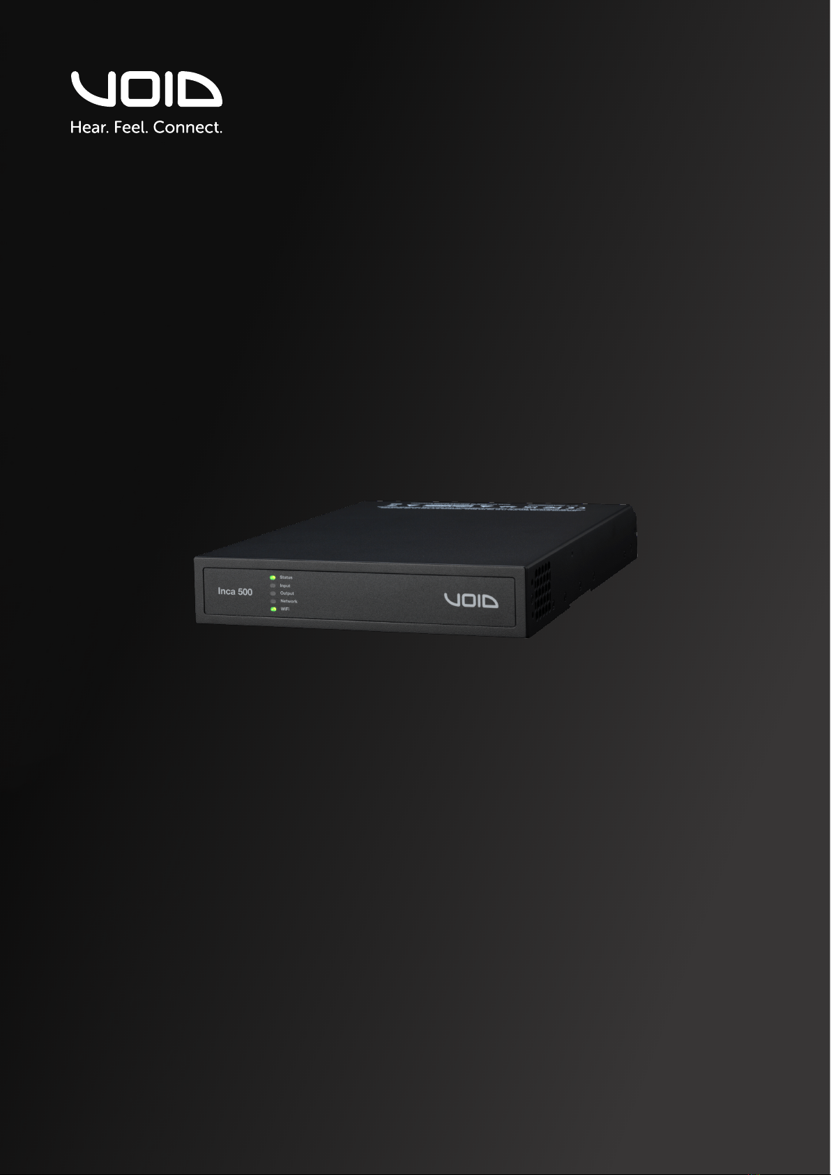
Page 4UG10637-1.0 - Inca 500 User Guide V1.0
1.1 Important safety instructions
The lightning flash with an arrowhead symbol
within an equilateral triangle is intended to alert the
user to the presence of uninsulated “dangerous
voltage” within the product’s enclosure that may
be of sucient magnitude to constitute a risk of
electric shock to persons.
The exclamation point within an equilateral triangle
is intended to alert the user of the presence of
important operating and maintenance (servicing)
instructions in the literature accompanying the
appliance.
Safety instructions - read this first
1. Read these instructions.
2. Keep these instructions.
3. Heed all warnings.
4. Follow all instructions.
5. Do not use this apparatus near water.
6. Do not submerge the equipment in water or liquids.
7. Do not use any aerosol spray, cleaner, disinfectant or
fumigant on, near or into the equipment.
8. Clean only with a dry cloth.
9. Do not block any ventilation opening. Install in accordance
with the manufacturer’s instructions.
10. Do not install near any heat sources such as radiators, heat
registers, stoves, or other apparatus (including amplifiers) that
produce heat.
11. To reduce the risk of electrical shock, the power cord shall be
connected to a mains socket outlet with a protective earthing
connection.
12. Do not defeat the safety purpose of the polarized or
grounding type plug. A polarized plug has two blades with
one wider than the other. A grounding type plug has two
blades and a third grounding prong. The wide blade or the
third prong are provided for your safety. If the provided
plug does not fit into your outlet, consult an electrician for
replacement of the obsolete outlet.
13. Protect the power cord from being walked on or pinched
particularly at plugs, convenience receptacles, and the point
where they exit from the apparatus.
14. Do not unplug the unit by pulling on the cord, use the plug.
15. Only use attachments/accessories specified by the
manufacturer.
16. Unplug this apparatus during lightning storms or when
unused for long periods of time.
17. Refer all servicing to qualified service personnel. Servicing is
required when the apparatus has been damaged in any way,
such as power supply cord or plug is damaged, liquid has
been spilled or objects have fallen into the apparatus, the
apparatus has been exposed to rain or moisture, does not
operate normally, or has been dropped.
18. The appliance coupler, or the AC Mains plug, is the AC mains
disconnect device and shall remain readily accessible after
installation.
19. Adhere to all applicable, local codes.
20. Consult a licensed, professional engineer when any doubt or
questions arise regarding a physical equipment installation.
1.2 Limitations
This guide is provided to help familiarise the user with the
loudspeaker system and its accessories. It is not intended to
provide comprehensive electrical, fire, mechanical and noise
training and is not a substitute for industry-approved training. Nor
does this guide absolve the user of their obligation to comply
with all relevant safety legislation and codes of practice. While
every care has been taken in creating this guide, safety is user-
dependent and Void Acoustics Research Ltd cannot guarantee
complete safety whenever the system is rigged and operated.
1.3 EC declaration of conformity
For EC Declaration of Conformity please go to:
www.voidacoustics.com/eu-declaration-amplifiers
1.4 UKCA marking
For details of the UKCA marking go to:
www.voidacoustics.com/uk-declaration-amplifiers
1.5 Warranty statement
For warranty statement go to:
https://voidacoustics.com/terms-conditions/
1.6 WEEE directive
If the time arises to throw away your product,
please recycle all the components possible.
This symbol indicates that when the end-user
wishes to discard this product, it must be sent
to separate collection facilities for recovery
and recycling. By separating this product
from other household-type waste, the volume of waste sent to
incinerators or land-fills will be reduced and natural resources will
thus be conserved.
The Waste Electrical and Electronic Equipment Directive (WEEE
Directive) aims to minimise the impact of electrical and electronic
goods on the environment. Void Acoustics Research Ltd complies
with the Directive 2002/96/EC and 2003/108/EC of the European
Parliament on waste electrical finance the cost of treatment and
recovery of electronic equipment (WEEE) in order to reduce the
amount of WEEE that is being disposed of in land-fill sites. All of
our products are marked with the WEEE symbol; this indicates that
this product must NOT be disposed of with other waste. Instead
it is the user’s responsibility to dispose of their waste electrical
and electronic equipment by handing it over to an approved
reprocessor, or by returning it to Void Acoustics Research Ltd for
reprocessing. For more information about where you can send
your waste equipment for recycling, please contact Void Acoustics
Research Ltd or one of your local distributors.
1 Safety and Regulations

Page 5UG10637-1.0 - Inca 500 User Guide V1.0
Please read the following important technical, safety
and environmental notices before installing and using
your amplifier.
Technical Notices
All reasonable design and engineering steps have been taken
to ensure that these amplifiers always perform satisfactorily in
their intended application and environment and will provide
appropriate levels of support to ensure that all reasonable
customer needs and expectations are met. Such support
however is contingent on the following provisions.
1. These amplifiers are Class-I products and should be
installed with a mains cable including the required earth
connection to comply with the Safety Class-I.
2. These amplifiers should always be installed by competent
and qualified personnel. Amplifier damage or failure caused
by installation or operational errors may invalidate support,
warranty or guarantees of performance.
3. These amplifiers are not suitable for use in locations where
they may be accessible to minors.
4. These amplifiers are intended to be used specifically for
the amplification of audio signals and for connection to
moving-coil loudspeaker systems. Use of these amplifiers
for amplification of signals outside the audio band (20Hz
to 20kHz) or to drive transducers other than moving-coil
loudspeakers may invalidate support, warranty or guarantees
of performance.
5. These amplifiers should only be used within professionally
installed and configured audio systems comprising input
and output ancillary equipments that is known to be of an
appropriate level of performance and in good operating
condition. Any damage to, or unsatisfactory performance
from, these amplifiers caused by inadequate or failed input
or output ancillaries may invalidate support, warranty or
guarantees of performance.
6. These amplifiers are intended to be installed and operated
indoor in a controlled environment (pollution degree, PD2)
within an ambient temperature range of 0°C to 40°C. These
amplifiers are not intended for use above 2000 meters above
sea level. Amplifiers installation or operated in environments
outside these limits may invalidate support, warranty or
guarantees of performance.
Safety and Environmental Notices
WARNING! TO PREVENT FIRE OR ELECTRIC SHOCK,
DO NOT EXPOSE THIS EQUIPMENT TO RAIN OR
MOISTURE.
Ambient Temperature Note: If this
equipment is operated in a confined or
multiple rack installation, the internal
ambient operating temperature
may exceed the external ambient
temperature. It is important to ensure in
these circumstances that the published
maximum operating temperature for the equipment is
not exceeded.
Reduced Air Flow: Ensure that rack or
other closed installation does not restrict
the cooling airflow required for safe and
reliable operation of the equipment.

Page 6UG10637-1.0 - Inca 500 User Guide V1.0
2 Unpacking and Checking
All Void Acoustics products are carefully manufactured and thoroughly tested before being
despatched. Your dealer will ensure that your Void products are in pristine condition before
being forwarded to you but mistakes and accidents can happen.
Before signing for your delivery:
• Inspect your shipment for any signs of contamination, abuse or transit damage as soon
as you receive it
• Check your Void Acoustics delivery fully against your order
• If your shipment is incomplete or any of its contents are found to be damaged; inform
the shipping company and inform your dealer.
Carton Contents
Inca 500 amplifiers are shipped in a cardboard carton containing the amplifier unit, a mains
cable appropriate for the sales territory, an accessory pack, and a document pack. The full
contents is listed below.
• Amplifier unit
• Mains power cable
• Input connector x 2
• GPIO socket connector
• Output connector x 2
• Adhesive rubber feet x 4
• Document pack

Page 7UG10637-1.0 - Inca 500 User Guide V1.0
3 About
3.1 Welcome
Many thanks for purchasing this Void Acoustics Inca Series amplifier. We truly appreciate your
support. At Void, we design, manufacture and distribute advanced professional audio systems
for the installed and live sound market sectors. Like all Void products, our highly skilled and
experienced engineers have successfully combined pioneering technologies with ground-
breaking design aesthetics, to bring you superior sound quality and visual innovation. In buying
this product, you are now part of the Void family and we hope using it brings you years of
satisfaction. This guide will help you both use this product safely and ensure it performs to its
full capability.
3.2 Inca 500 overview
The Inca 500 amplifier is a half rack width, 1U format power amplifier that can drive both
conventional low impedance (Low-Z, 4Ωto 16Ω) loudspeakers and high impedance (Hi-Z,
70V/100V) transformer coupled loudspeakers. The Inca 500 provides four analog inputs, one
stereo S/PDIF digital input, and four outputs (Low-Z mode) or two outputs (Hi-Z mode). It is
capable of a maximum output of 125 Watts per channel into Low-Z loads or 250 Watts per
channel into Hi-Z loads. The Inca 500 also incorporates automatic power sharing technology
that enables 250 Watts to be shared proportionately as required across each output pair in
Low-Z mode and the two outputs in Hi-Z mode.
3.3 Key features
• Full matrix DSP embedded and controlled via TCP/IP
• Master / Slave functionality – S/PDIF link to multiple amps
• Market proven reliability
• Automatic power sharing
• Small size with flexible mounting

Page 8UG10637-1.0 - Inca 500 User Guide V1.0
3 About
3.4 Connections
Inca 500 signal input and output connections are accomplished via RCA Phono and
Euroblock style connectors. A GPIO (General Purpose In/Out) Euroblock connector enables
some amplifier functions to be controlled, and wireless or RJ45 socket Ethernet network
connection options are also provided.
Inca 500 amplifiers have no mains power switch and are operational as soon as mains power
is connected via the IEC 60320 mains socket.
3.5 Network Features
Inca 500 amplifiers are TCP/IP network connected devices that require a wired or wireless
network connection to access their configuration menus. The configuration menus are
accessed via a web page interface and cover Input, Zone, Output and General Settings
functions. The configuration menus are fully described in Section 5 of this manual.
3.6 Dimensions
Inca 500 amplifier dimensions and features are illustrated in figure 3.1. The amplifiers are
primarily intended for installation in an equipment rack but can also be under-desk or
wall mounted, or used free standing. They are fan-cooled and must be installed such that
ventilation apertures are not obstructed.
44 mm
1.7 in
220 mm
8.7 in
80 mm
3.1 in
319 mm
12.6 in
25 mm
1.0 in
Figure 3.1: Inca 500 four channel amplifier dimensions.
Shaded area defines ventilation space.

Page 9UG10637-1.0 - Inca 500 User Guide V1.0
Note: The rack mounting and desk/wall
mounting components described and
illustrated in Sections 4.1 to 4.3 are not supplied
with Inca 500 amplifiers but are available
to purchase as accessories. Contact sales@
voidacoustics.com for more information.
4.1 Inca 500 Mounting
The Inca 500 amplifiers are shipped without
rack mount hardware attached but can be
configured for rack installation using one
standard rack ‘ear’ and one half-rack extension
piece as illustrated in figure 4.1. The
installation and equipment rack should
be configured to provide appropriate
ventilation airflow space around the sides
and rear of the amplifier as illustrated in as
illustrated in figure 3.1. Ventilation airflow
space of at least 25 mm (1 in) should be
maintained along at least one side of the
amplifier at all times. Ventilation apertures
are also located on the rear panel of the
amplifier and must not be obstructed. It is
important to retain at least 80 mm (3.1 in)
free space for airflow behind the amplifier
rear panel.
In addition to rack mount ears, optional
rack mount rear support hardware is
available and can be attached
to the amplifier. Rear support
hardware may be appropriate if the
amplifier is to be used in a mobile
rack or potentially be subject to
significant movement. Figure 4.2
illustrates the use of rack mount
rear support hardware.
Multiple Inca 500 amplifiers can
also be mechanically connected
using accessory connecting plates.
Figure 4.3 illustrates the use of
connecting plates.
4 Installation
Figure 4.1: Inca 500 Rack Ear + Half-rack Extension.
Rack Ear +
2 x M4 x 8 countersink
Half-rack Extension +
2 x M4 x 8 countersink
Figure 4.2: Inca 500 Rack Support hardware. 2 positions.
Rear Support + Button +
1 x M4 x 8
Connection Plate +
4 x M3 x 6 countersunk
Figure 4.3: 2 x Inca 500 with Connection Plate. 2 positions

Page 10UG10637-1.0 - Inca 500 User Guide V1.0
4 Installation
Figure 4.5: Inca 500 wall and under-desk mount.
4.2 Free-standing
If not installed in an equipment
rack, Inca 500 amplifiers can be
placed free-standing on a flat
surface. Adhesive rubber feet are
supplied for this purpose.
Inca 500 amplifiers can also be
attached to the underside of desks
or wall mounted using connecting
plate hardware. The adhesive
rubber feet should also be used in
these circumstances to minimise
the possibility of vibration between
the amplifier and mounting
surface. Wall and desk mounting is
illustrated in figure 4.4 and 4.5.
It is important in any free standing
installation that airflow through
the amplifier’s side
panel mounted
fans and rear panel
ventilation apertures is
not compromised by
adjacent items. At least
80mm of free space
behind the amplifier
and 25mm along at
least one side should
be retained at all times.
Figure 4.4: Inca 500 with desk/wall Mounting Plate and
adhesive feet. 2 positions and 4 positions.
Mounting Plate +
2 x M3 x 6 countersunk
Adhesive Foot
4 positions

Page 11UG10637-1.0 - Inca 500 User Guide V1.0
5 Configurations
Before making input, output and GPIO connections, an initial Inca 500 amplifier
configuration should be established. It is particularly important that the amplifier output
format is configured appropriately for the speakers that are to be connected.
Configuration requires that Inca 500 amplifiers are connected to mains power and network
services. These connections are described in the following two sections.
5.1 Mains Power Connection
Inca 500 amplifiers incorporate a power factor corrected power supply and can be used
with mains input voltage from 100V AC to 240V AC, 50/60Hz. Use the mains cable supplied
with the amplifier and connect it to a switched mains supply.
Inca 500 amplifiers have no mains power switch and are operational as soon as mains
power is connected.
5.2 Network Services
Inca 500 amplifiers are configured via a web page interface called. Before the configuration
menus can be accessed, Inca 500 amplifiers must be connected to the same TCP/IP
network as the computer or mobile device that is to be used for configuration access.
5.2.1 Wired (Ethernet) Network Connection
To connect an Inca 500 amplifier to a TCP/IP network using a wired connection (Ethernet)
follow the steps below.
1. Use an Ethernet cable to connect the Inca 500 amplifier rear panel Network Control
socket to a free socket on a network router or switch, or directly to an Ethernet equipped
laptop or desktop computer.
2. Connect the Inca 500 amplifier to mains power using the supplied mains cable. Wait
for the front panel Network indicator to illuminate green to indicate that the amplifier has
network connectivity.
3. The Inca 500 amplifier default LAN IP address is 192.168.64.100. Configure the laptop
or desktop computer for a fixed IP address in the same IP range; eg. 192.168.64.10, with
Subnet mask of 255.255.255.0 (or prefix 24) and set the Gateway to 192.168.64.1.
4. Open a laptop or desktop web browser and enter the address http://192.168.64.100. The
Inca 500 Web App interface will open to enable amplifier configuration as required.
Note: Inca 500 amplifiers can be configured to use DHCP for network connection if
required. However, if an Inca 500 amplifier using DHCP is power cycled, it is possible that
the TCP/IP network router will assign it a dierent IP address, leaving its configuration page
inaccessible via the previous address. If this occurs, a network scanning app can be used to
identify the new IP address. DHCP and Fixed IP address option settings can be found in the
Settings Tab menu described in Section 5.3.

Page 12UG10637-1.0 - Inca 500 User Guide V1.0
5.2.2 Wireless (WiFi) Network Connection
To connect an Inca 500 amplifier to a TCP/IP network using a wireless connection (WiFi)
follow the steps below.
1. With the Inca 500 amplifier connected to mains power, wait for the front panel WiFi
indicator to illuminate green.
2. Use a mobile, laptop or desktop device to search for available WiFi networks. Connect
to, Inca 500 (product serial number)’ using the password, ‘password’. The amplifier serial
number can be found on its rear panel.
3. Open a computer or mobile device web browser and enter the IP address: 192.168.4.1.
The Inca 500 Web App interface will open to enable amplifier configuration as required.
4. Select the Web App Settings Tab followed by WiFi > WiFi Mode > Client to configure the
amplifier to connect to the required WiFI network. The WiFi network name and password
will be required.
It is strongly recommended that the Inca 500 amplifier Access Point WiFi password is
changed following initial wireless connection.
5 Configurations

Page 13UG10637-1.0 - Inca 500 User Guide V1.0
Input name - type to edit
Select input sensitivity option
Adjust input gain
5 Configurations
Figure 5.1: Configuration Dashboard display
Figure 5.2: Input Tab display
Adjust zone volume
5.3 Configuration Menus
Opening a web browser that is network connected to an Inca 500 amplifier initially displays
the Inca 500 Web App Dashboard illustrated in figure 5.1. The Dashboard is the ‘home’ page
from which all other configuration options can be accessed.
The Dashboard displays the amplifier status, output zones and the configuration menu tabs.
It also enables immediate access to zone volume control The functions available under
each configuration menu tab are described in the following sections.
5.3.1 Input Tab
The Input Tab provides naming, mono/stereo selection, sensitivity, and gain trim for each
amplifier input channel. An internal pink noise source, provided for system testing and
set up, can also enabled or disabled, and adjusted for gain via the Input Tab. Figure 5.2
illustrates the Input Tab.
Note: When adjusting input gain, the input level display should remain green. If it displays
red, the input gain should be reduced.
Adjust zone volume

Page 14UG10637-1.0 - Inca 500 User Guide V1.0
5 Configurations
5.3.2 Zone Tab
The Zone Tab enables installation zones to be defined and named, and provides access to
further sub-menus. Zones might be bar or restaurant areas for example, or dierent rooms
in a home. For all Zone Tab menus, the installation zone under configuration is selected
by highlighting one of the zone identifiers (A, B, C or D) at the top of the page. Figure 5.3
illustrates the Zone Tab.
• The Source menu option enables inputs to be assigned to zones.
• The GPIO Volume Control option enables external volume control to be applied to
individual zones. The GPIO configuration menu can be found under the Settings Tab.
• The Compressor option enables default or custom signal compression to be applied to
individual installation zones.
Note: Compression can be useful to reduce the volume dierence between loud and
quiet audio material. The lower the compression threshold is set, the more the dierence
between loud and soft will be reduced. The overall zone volume may need to be increased
when compression is used. The default compression parameters are appropriate for most
installations.
Zone name - type to edit
Select zone
Select mono or stereo
Select input
Adjust zone volume
Figure 5.3: Zone Tab display

Page 15UG10637-1.0 - Inca 500 User Guide V1.0
5.3.3 Output Tab
The Output Tab enables amplifier outputs to be named and provides access to further
sub-menus. For all Output Tab menus, the amplifier output under configuration is selected
by highlighting one of the output identifiers (1, 2, 3 or 4) at the top of the display. The
Output Tab also enables Speaker Preset configurations to be created, exported, imported or
cleared. Figure 5.4 illustrates the Output Tab.
• The Routing menu enables zones to be assigned to amplifier outputs.
Note: Routing for zones specified as stereo will automatically oer three output options:
left channel, right channel or summed mono. The summed mono signal can potentially be
used to drive a mono subwoofer.
• The Delay menu enables delay to be applied to individual amplifier outputs.
• The Equalizer menu enables parametric equalization to be applied to individual amplifier
outputs. Equalizer settings configured for one amplifier output can be copied and applied
to other outputs.
Output name - type to edit
Select output
Select zone
Figure 5.4: Output Tab display
5 Configurations

Page 16UG10637-1.0 - Inca 500 User Guide V1.0
5 Configurations
Figure 5.6: Speaker Preset import file selection
Figure 5.5: Speaker Preset Parameters
• The Speaker Preset menu enables speaker parameters to be adjusted, and preset
configurations to be created. Speaker Presets can be simply applied to the selected
amplifier output or exported, imported or cleared. The preset configurations can include
any or all of the parameters described in the following paragraphs and can be protected
to prevent inadvertent modification. Figures 5.5 to 5.7 illustrate the application of speaker
presets.
Note: When the Speaker Preset menu is initially selected, the preset menu parameters will
display only once the “Create Custom” button is selected.
Speaker Preset data provided by third parties for use with specific speakers can be imported
and applied to amplifier outputs. To import speaker preset parameters follow the steps
described below and illustrated in the diagrams.
1. Select the IMPORT option from the Speaker Preset menu. If no import option is visible,
select CLEAR to delete any existing speaker preset data.
2. Select the appropriate ‘.zcp’ format speaker preset data file to import. The preset data
will be applied to the selected amplifier output as soon as the file import is complete.

Page 17UG10637-1.0 - Inca 500 User Guide V1.0
5.3.4 Speaker Preset Menu Parameters
• The Crossover & Gain preset menu enables high or low-pass crossover filters and gain
adjustment to be applied to individual amplifier outputs.
• The Speaker EQ preset menu enables parametric equalization to be applied to individual
amplifier outputs.
• The FIR preset menu enables FIR (Finite Impulse Response) based equalization filter
coecients generated by external speaker measurement software to be imported and
applied to individual amplifier outputs.
Note: FIR coecient files in either .csv or .txt format can be imported.
• The Driver Alignment preset menu enables delay to be applied to individual amplifier
outputs.
• The Polarity preset menu enables the polarity of individual amplifier outputs to be
reversed.
• The Limiter preset menu enables signal limiting to be applied to individual amplifier
outputs. Clip limiting, peak limiting and RMS limiting can be individually or collectively
engaged. The Peak limiter can be set to either automatic or custom parameter values.
The RMS limiter has default parameter values that can be adjusted but has no automatic
option.
Note: In automatic mode, the peak limiter parameters adjust automatically in response to
Crossover & Gain high-pass filter settings.
• The Output Mode preset menu enables individual amplifier outputs to be switched
o or configured for Lo-Z or Hi-Z modes. In Hi-Z modes, a high-pass filter can also be
configured and applied to the output. The number of outputs available will depend on
the amplifier model, input setup and zone setup. For example, a two output amplifier will
have two outputs available if Lo-Z mode is selected but only one output available if Hi-Z
mode is selected.
Note: Use of a high-pass filter with Hi-Z mode loudspeakers is useful to avoid the possibility
of distortion caused by low frequency line transformer saturation. Begin with the default
filter setting of 70Hz. If low frequency distortion is still audible, increase the frequency
setting one step at a time until the distortion is no longer audible.
5 Configurations

Page 18UG10637-1.0 - Inca 500 User Guide V1.0
5.3.5 Settings Tab
The Settings Tab enables miscellaneous amplifier settings to be configured and installation
data to be recorded. The Settings Tab provides access to further sub-menus. Figure 5.10
illustrates the Settings Tab.
• The System Information menu
provides text fields for the recording
of installation data.
• The Device menu records amplifier
specific information such as the
model number and firmware version.
A firmware update routine and
identifier button can also be found
under the Device menu.
• The Backup & Restore menu enables
amplifier configuration data to be
downloaded to an external archive,
and enables previously saved
configuration files to be uploaded
and adopted by the currently
connected amplifier.
• The Power Management menu enables various automatic switch-on options to
be engaged. The Power Management menu also oers timed Standby and Mute
functions.
• The GPIO menu enables configuration of the multi-purpose GPIO interface pins.
• The LAN menu enables configuration and reset of the wired network options and
parameters.
• The WiFi menu enables configuration and reset of the wireless network options and
parameters.
5.4 Setup and Signal Routing
Thanks to their network based configuration features, Inca 500 amplifiers oer considerable
versatility in terms of sources, signal routing, installation zones and output modes. Inputs
can be freely assigned to installation zones, and those zones assigned freely to the available
amplifier outputs in either Lo-Z or Hi-Z modes.
This versatility enables, for example, one amplifier simultaneously to drive both Lo-Z and
Hi-Z speakers, or for dierent inputs to be routed to dierent output zones.
The following paragraphs describe and illustrate the recommended procedure for
configuring input, zone and output routing. A general signal flow schematic is also
illustrated in figure 5.11.
5 Configurations
Figure 5.7: Settings Tab menu

Page 19UG10637-1.0 - Inca 500 User Guide V1.0
5.4.1 Input Setup
Open the configuration Dashboard and select the Input Tab. The Input Tab is shown in
figure 5.2.
• To edit default input names simply select and type in the Input Name field.
• Define a mono or stereo input by selecting the appropriate option. Defining a stereo
input will reduce the total number of discrete inputs available.
• Select an input sensitivity option from the drop-down menu: +14dB, +4dB, -10dB
and ‘microphone’ options are available. Generally, the +14dB or +4dB options are
appropriate for ‘professional audio’ source hardware with balanced outputs, while
the -10dB option is more appropriate for ‘consumer audio’ source hardware with
unbalanced outputs. The ‘microphone’ option provides the significantly greater
sensitivity required for microphones.
Note: Only dynamic microphones are suitable for connection. Phantom power for
condenser microphones is not provided.
• If necessary, adjust the input gain using the slider or up/down icons. Gain adjustment
is intended to be used for fine output level adjustment following initial use.
5.4.2 Zone Setup & Routing
Open the configuration Dashboard and select the Zone Tab. The Zone Tab is shown in
figure 5.3.
• Select the zone to be configured. The number of zones available and their channel
format (stereo or mono) will depend on the input setup and output mode (Lo-Z or Hi-Z).
• A four output amplifier can have the following zones configured:
• 2 x stereo Lo-Z zones
• 4 x mono Lo-Z zones
• 2 x mono Hi-Z zone
• 1 x mono Hi-Z zone + 1 x stereo Lo-Z zone
• 1 x mono Hi-Z zone + 2 x mono Lo-Z zones
Note: When configured in Hi-Z mode Inca 500 amplifiers operate in ‘bridged’ mode where
the output of two channels is combined. This means that the number of output channels
available in Hi-Z mode is half that available in Lo-Z mode .
Note: Mono signals might be mono at source, created though combining the left and right
channels of a stereo signal (summed mono) or treating the left and right channels of a
stereo signal independently (split mono).
5 Configurations

Page 20UG10637-1.0 - Inca 500 User Guide V1.0
Analog 3
Output
Matrix
Zones A - D
Outputs 1 - 4
Analog 2
Input
Sensitivity
Analog 1
Input
Gain
Input
Sensitivity
Input
Gain
Input
Sensitivity
Input
Gain
Analog 4
SPDIF (stereo)
SPDIF Out (stereo).
Zones A (left) and B (right)
Pink Noise Gain
Delay
Level
Adjustment
Level
Adjustment
Level
Adjustment
Level
Adjustment
Compressor
Compressor
Compressor
Compressor
Delay
Delay
Delay
EQ
EQ
EQ
EQ
EQ
EQ
EQ
EQ
FIR
FIR
FIR
FIR
Polarity
Polarity
Polarity
Polarity
Limiter
BTL
Amplifier
2 x Low-Z
1 x Hi-Z
BTL
Amplifier
2 x Low-Z
1 x Hi-Z
Limiter
Limiter
Limiter
Driver
Alignment
Driver
Alignment
Driver
Alignment
Driver
Alignment
Crossover
Crossover
Crossover
Crossover
Gain Trim
Gain Trim
Gain Trim
Gain Trim
Input
Sensitivity
Input
Gain
Input
Gain
Input
Selection
Input Setup
Zone Setup & Routing
Output Setup
Output 1
Output 2
Output 3
Output 4
Zone Adjustment Parameters Speaker Preset Parameters
5 Configurations
• Name zones by typing in the Zone Name field.
• Adjust the zone volume if required by using the slider.
• Define a mono or stereo zone by selecting the appropriate option. Defining a stereo
zone will reduce the total number of further zones available.
• Specify an input for the zone by selecting from the drop-down menu. Selecting a stereo
input for a mono zone will automatically sum the stereo channels to mono.
Figure 5.8: Signal Flow Schematic
Table of contents
Other Void Amplifier manuals