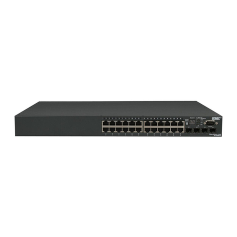
VoIP VM-S1024PEG-C User manual

24-Port 10/100/1000M
POE Web Smart Ethernet Switch
User Manual
Ver 1.0

Gigabit POE Web Smart Ethernet Switch
1
Table of Content
Chapter 1 Product Introduction ............................................................................3
1.1 Product Overview.................................................................................................. 3
1.2 Features................................................................................................................ 3
1.3 External Component Description............................................................................ 3
1.3.1 Front Panel...................................................................................................... 3
1.3.2 Rear Panel...................................................................................................... 4
1.3.3 LED Indicator Specification.............................................................................. 4
1.4 Environment.......................................................................................................... 5
1.5 Package Contents................................................................................................. 5
Chapter 2 Hardware Installation............................................................................6
2.1 Installation............................................................................................................. 6
2.1.1 Desktop/Horizontal Installation ........................................................................ 6
2.1.2 Rack-mountable Installation in 19-inch Cabinet............................................... 6
2.1.3 Power on the Switch........................................................................................ 7
2.2 Connect Computer (NIC) to the Switch ................................................................. 7
2.3 Switch connection to the PD.................................................................................. 8
Chapter 3 How to Login the Switch......................................................................9
3.1 Switch to End Node ............................................................................................... 9
3.2 Howto Login the Switch ........................................................................................ 9
Chapter 4 Switch Configuration..........................................................................11
4.1 System Configuration............................................................................................11
4.1.1 Information.....................................................................................................11
4.1.2 IP Setting .......................................................................................................11
4.1.3 User Account..................................................................................................11
4.1.4 Port Setting....................................................................................................12
4.2 Configuration........................................................................................................13
4.2.1 VLAN .............................................................................................................14
4.2.1.1 Static VLAN.................................................................................................................................14
4.2.1.2 Port based VLAN ....................................................................................................................... 14
4.2.2 Qos................................................................................................................15
4.2.2.1 Port-based Priority..................................................................................................................... 15
4.2.2.2 Packet Scheduling..................................................................................................................... 16
4.2.3 Trunk Setting..................................................................................................17
4.2.4 Port-based Mirroring.......................................................................................17
4.2.5 Port Isolation..................................................................................................18
4.2.6 Bandwidth Control..........................................................................................19
4.2.7 Jumbo Frame.................................................................................................20
4.2.8 Loop Detection and Prevention.......................................................................20
4.2.9 Green Ethernet...............................................................................................20
4.3 Security................................................................................................................20
4.3.1 MACAddress.................................................................................................21

Gigabit POE Web Smart Ethernet Switch
2
4.3.1.1 MAC Forwarding Table.............................................................................................................21
4.3.1.2 Static MAC..................................................................................................................................21
4.3.2 MAC Constrain...............................................................................................21
4.3.3 Storm Control.................................................................................................23
4.4 Monitoring.............................................................................................................23
4.4.1 Port Statistics.................................................................................................24
4.4.2 Cable Diagnostic............................................................................................24
4.5 Tools.....................................................................................................................25
4.5.1 HTTP Upgrade...............................................................................................25
4.5.2 Reset.............................................................................................................26
4.5.3 Save...............................................................................................................26
4.5.4 Reboot...........................................................................................................26

Gigabit POE Web Smart Ethernet Switch
3
Congratulations on your purchasing of the Gigabit POE Web Smart Ethernet Switch.
This Switch provides a simple, economical, standard and high performance solution for
you. Please read the entire user manual before using the product and save it for future
reference.
Chapter 1 Product Introduction
1.1 Product Overview
The 24-port 10/100/1000M POE Web Smart Ethernet Switch provides the seamless
network connection. It integrates 10/100/1000Mbps Ethernet network capabilities. These
POE ports can automatically detect and supply power with those IEEE 802.3at compliant
Powered Devices (PDs). In this situation, the electrical power is transmitted along with
data in one single cable allowing you to expand your network where there are no power
lines or outlets, where you wish to fix devices such as APs, IP Cameras or IP Phones, etc.
The Switch is web smart switch, and can be configured by web based interface. Including
System, Configuration, Security, Monitoring, Tools and so on.
1.2 Features
Complies with IEEE802.3, IEEE 802.3u, IEEE 802.3ab standards
24 x 10/100/1000Mbps Auto-Negotiation RJ45 ports supporting Auto-MDI/MDIX
Supports PoE power up to 30W for each PoE port
Supports PoE power up to 260W for all PoE ports
Supports PoE IEEE802.3at compliant PDs
Supports IEEE802.3x flow control for Full-duplex Mode and backpressure for
Half-duplex Mode
16K entry MAC addresstable of the Switch with auto-learning and auto-aging
Supports WEB management interface
LED indicators for monitoring power, link, activity, speed and POE
1.3 External ComponentDescription
1.3.1 Front Panel
The front panel of the Switch consists of 24 x 10/100/1000Mbps RJ-45 ports and a series
of LED indicators shown as below.

Gigabit POE Web Smart Ethernet Switch
4
1~24:24 x RJ-45 Ethernet interfaces, 10 M/100M/1000M self-adaptive.
Reset: Keep the device powered on and push a paper clip into the hole. Press down the
button for about 5 seconds. The system restores the factory default settings.
1.3.2 Rear Panel
The rear panel of the Switch contains AC power connector and one marker shown as
below.
AC Power Connector: Supports AC 100~240V, 50~60Hz.
1.3.3 LED Indicator Specification
The LED indicators of the Switch contain one Power, 24 LINK/ACT/SPEED and 24 PoE
status. You can see their operating situation through these LED indicators.
The following chart shows the LED indicators of the Switch along with explanation of each
indicator.
LED
COLOR
STATUS
STATUS DESCRIPTION
Power
Red
On
Power On
Off
Power off
LINK/ACT
/SPEED
Orange
(10/100M)
On
Connect to the port
Off
Disconnect to the port
Green
(1000M)
Flashing
Sending or receiving data
POE
Orange
On
Detect the PD
Off
The PD is not connected to or
detected
Flashing
Whenthe power which output to
PDs has exceeded the
maximum power budget

Gigabit POE Web Smart Ethernet Switch
5
1.4 Environment
Operating Temperature: 0℃~40℃
Storage Temperature: -10℃~70℃
Operating Humidity: 10%~90% non-condensing
Storage humidity: 5%~90% non-condensing
1.5 Package Contents
One Gigabit POE Web Smart Ethernet Switch
Four rubber feet, two mounting earsand eights screws
One AC power cord
One User Manual

Gigabit POE Web Smart Ethernet Switch
6
Chapter 2 Hardware Installation
2.1 Installation
Please follow the following instructions in avoid of incorrect installation causing
device damage and security threat.
Put the Switch on stable place or desktop in case of falling damage.
Make sure the Switch works in the proper AC input range and matches the voltage
labeled on the Switch.
To keep the Switch free from lightning, do not open the Switch‟s shell even in power
failure.
Make sure that there is proper heat dissipation from and adequate ventilation around
the Switch.
Make sure the cabinet to enough back up the weight of the Switch and its
accessories.
2.1.1 Desktop/Horizontal Installation
Sometimes users are not equipped with the 19-inch standard cabinet. So when installing
the Switch on a desktop, please attach these cushioning rubber feet provided on the
bottom at each corner of the Switch in case of the external vibration. Allow adequate
space for ventilation between the device and the objects around it. Please refer to the
following figure:
2.1.2 Rack-mountable Installation in 19-inch Cabinet
The Switch can be mounted in an EIA standard-sized, 19-inch rack, which can be placed
in a wiring closet with other equipment. To install, attach the mounting brackets on the
Switch‟s side panels (one on each side) and secure them with the screws provided.

Gigabit POE Web Smart Ethernet Switch
7
Then, use the screws provided with the equipment rack to mount the Switch on the rack
and tighten it.
2.1.3 Power on the Switch
The Switch is powered on by the AC 100-240V 50/60Hz internal high-performance power
supply. Please followthe next tips to connect:
AC Electrical Outlet
It is recommended to use single-phase three-wire receptacle with neutral outlet or
multifunctional computer professional receptacle. Please make sure to connect the metal
ground connector to the grounding source on the outlet.
AC Power Cord Connection
Step 1: Connect the AC power connector in the back panel of the Switch to external
receptacle with the included power cord.
Step 2: To check the power indicator is ON or not. When it is ON, it indicates the power
connection is OK.
2.2 Connect Computer (NIC) to the Switch
Please insert the NIC into the computer, after installing network card driver, please
connect one end of the twisted pair to RJ-45 jack of your computer, the other end will be
connected to any RJ-45 port of Switch, the distance between Switch and computer is
around 100 meters. Once the connection is OK and the devices are power on normally,
the LINK/ACT status indicator lights corresponding ports of the Switch.

Gigabit POE Web Smart Ethernet Switch
8
2.3 Switch connection to the PD
1-24 ports of Switch have POE power supply function, the maximum output power up to
30W each port, it can make PD devices, such as internet phone, network camera,
wireless access point work. You only need to connect the Switch POE port directly
connected to the PD port by network cable.

Gigabit POE Web Smart Ethernet Switch
9
Chapter 3 How to Login the Switch
3.1 Switch to End Node
Use standard Cat.5/5e Ethernet cable (UTP/STP) to connect the Switch to end nodes as
described below. Switch ports will automatically adjust to the characteristics (MDI/MDI-X,
speed, duplex) of the device to which is connected.
Please refer to the LED Indicator Specification. The LINK/ACT LEDs for each port lights
when the link is available.
3.2 How to Login the Switch
As the Switch provides Web-based management login, you can configure your computer‟s
IP address manually to log on to the Switch. The default settings of the Switch are shown
below.
Parameter
Default Value
Default IP address
192.168.2.1
Default user name
admin
Default password
admin
You can log on to the welcome window of the Switch through following steps:
1. Connect the Switch with the computer NIC interface.
2. Power on the Switch.
3. Check whether the IP address of the computer is within this network segment:
192.168.2.xxx (“xxx” ranges 2~254), for example, 192.168.2.100.
4. Open the browser, and enter http://192.168.2.1 and then press “Enter”. The Switch
login windowappears, as shown below.

Gigabit POE Web Smart Ethernet Switch
10
5. Enter the user name and password (The factorydefault login username and password
is admin), and then click “OK” to log in to the Switch configuration windowas below.
In the Web GUI, the left column shows the configuration menu and the rest of the screen
area displays the configuration settings.

Gigabit POE Web Smart Ethernet Switch
11
Chapter 4 Switch Configuration
4.1 System Configuration
There are "Information", "IP Setting", "User Account", "Port Setting" configuration web
pages in this section.
4.1.1 Information
Display basic information, includes Device Type, MAC Address, IP Address, Netmask,
Gateway, Firmware Version and Hardware Version.
4.1.2 IP Setting
Set IP address, subnet mask, and default gateway.
Parameters:
Mode specifies static IP or DHCP.
IP Address specifies the IP address of the system.
Subnet Mask specifies the subnet mask.
Gateway specifies the IP address of default gateway.
4.1.3 User Account
Set new user name, and password.

Gigabit POE Web Smart Ethernet Switch
12
Parameters:
New Username specifies the newuser name.
New Password specifies the password for the username.
Retype Password reconfirms the password.
4.1.4 Port Setting
Set state, speed/duplexand flowcontrol ability to specified ports.
Parameters:
Port specifies the ports to set.
State enable or disable the port state.
Speed/Duplex specifies port speed and duplex.
Flow Control specifies flowcontrol ability.

Gigabit POE Web Smart Ethernet Switch
13
Display the port configuration.
4.2 Configuration
There are "VLAN", "QoS" and "Others" configuration web pages in this section.

Gigabit POE Web Smart Ethernet Switch
14
4.2.1 VLAN
4.2.1.1 Static VLAN
Static VLAN configuration.
Parameters:
VLAN ID specifies VLAN ID, in the range 1 ~ 4094.
VLAN Name specifies the VLANname, up to 16 characters.
UnTagged/Tagged/Not Member specifies the member ports and port type.
Display the VLANconfiguration.
4.2.1.2 Port based VLAN
Port-based VLANconfiguration.
Parameters:
PVID specifies the Port VLANID.

Gigabit POE Web Smart Ethernet Switch
15
Display the VLANconfiguration.
4.2.2 Qos
4.2.2.1 Port-based Priority
Port-based(802.1p default) priority configuration.
Parameters:
Port specifies the ports to set.
Priority Queue specifies the 802.1p priority value.

Gigabit POE Web Smart Ethernet Switch
16
Display the port-based priority information.
4.2.2.2 Packet Scheduling
Packet scheduling configuration.
Scheduling Algorithm specifies the Weight-fair-queue or Weight-round-robin of
scheduling algorithm.
Priority Queue specifies queue ID.
Weight specifies the weight of queue, the value could be strict priority or 1~15.

Gigabit POE Web Smart Ethernet Switch
17
Display the packet scheduling information.
4.2.3 Trunk Setting
Trunk group configuration.
Parameters:
Group ID specifies trunk group.
Port specifies the trunk member port.
Display the information of trunks.
4.2.4 Port-based Mirroring
Port-based mirror configuration.
Parameters:
Mirror Set Index specifies mirror set 1 or 2.
Mirror Direction specifies to monitor RX(Ingress) or TX(Egress).
Mirroring Port specifies analysis port on which traffic would be forwarded for analysis.

Gigabit POE Web Smart Ethernet Switch
18
Mirrored Port List specifies monitored ports. The traffic of these ports would be mirrored
to mirroring port.
Display the information of port mirror.
4.2.5 Port Isolation
Port-based mirror configuration.
Parameters:
Port specifies Isolation Port.
Port Isolation List specifies Port Isolation List.
Display the configuration of Port Isolation.

Gigabit POE Web Smart Ethernet Switch
19
4.2.6 Bandwidth Control
Bandwidth control configuration.
Parameters:
Port specifies the port to set.
Type specifies ingress or egress rate to set.
State enable or disable bandwidth control.
Rate specifies the rate, in range 0-1048544 kbps and must be a multiple of 16.
Display the configuration of bandwidth control.
Table of contents
Popular Network Router manuals by other brands
Cisco
Cisco ASR1002 - ASR 1002 Router Software configuration guide
AVM
AVM FRITZ!Box 7590 quick guide
Cisco
Cisco EF4116 Hardware installation and maintenance manual

TRENDnet
TRENDnet DSLR-2000G user manual
SONIQ
SONIQ CWR300ND-AU instruction manual
Carrier Access
Carrier Access 002-0118-0180 quick start guide

