Jntech JNF3KLF24V-V2 User manual

User Manual
PV Off-Grid Inverter With
Controller
JNF3KLF24V-V2
JNF3KLF48V-V2
JNF4KLF48V-V2
JNF5KLF48V-V2
JNF3KLF24V-A-V2
JNF3KLF48V-A-V2
JNF4KLF48V-A-V2
JNF5KLF48V-A-V2
JNF5KLF-V2-EN-V2.0

Copyright belongs to Supplier
This document relates to the patents and confidential information of Supplier
It is not allowed to copy, take pictures and distribute online, without the permission
of supplier.
Supplier has rights to modify the user manual.

Content
1 Safety Instruction..................................................................................................................... 1
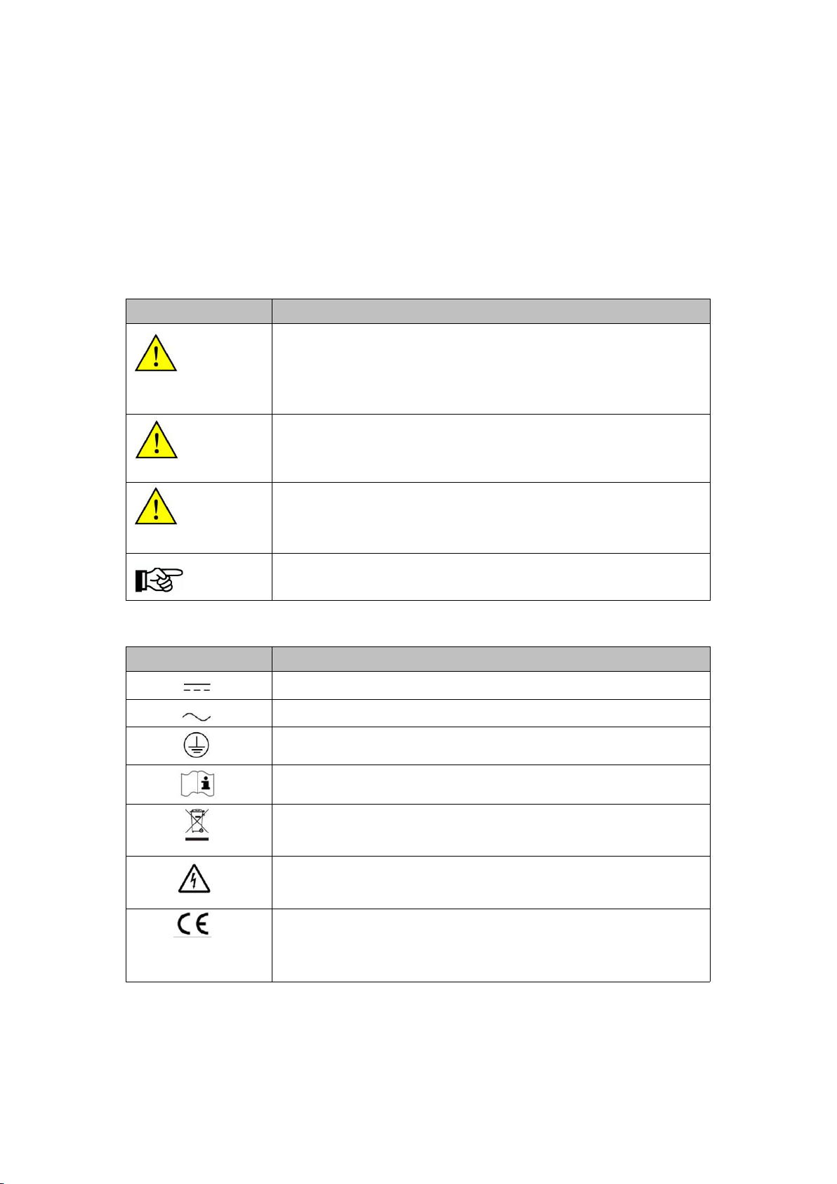
1.1 Safety identification........................................................................................................1
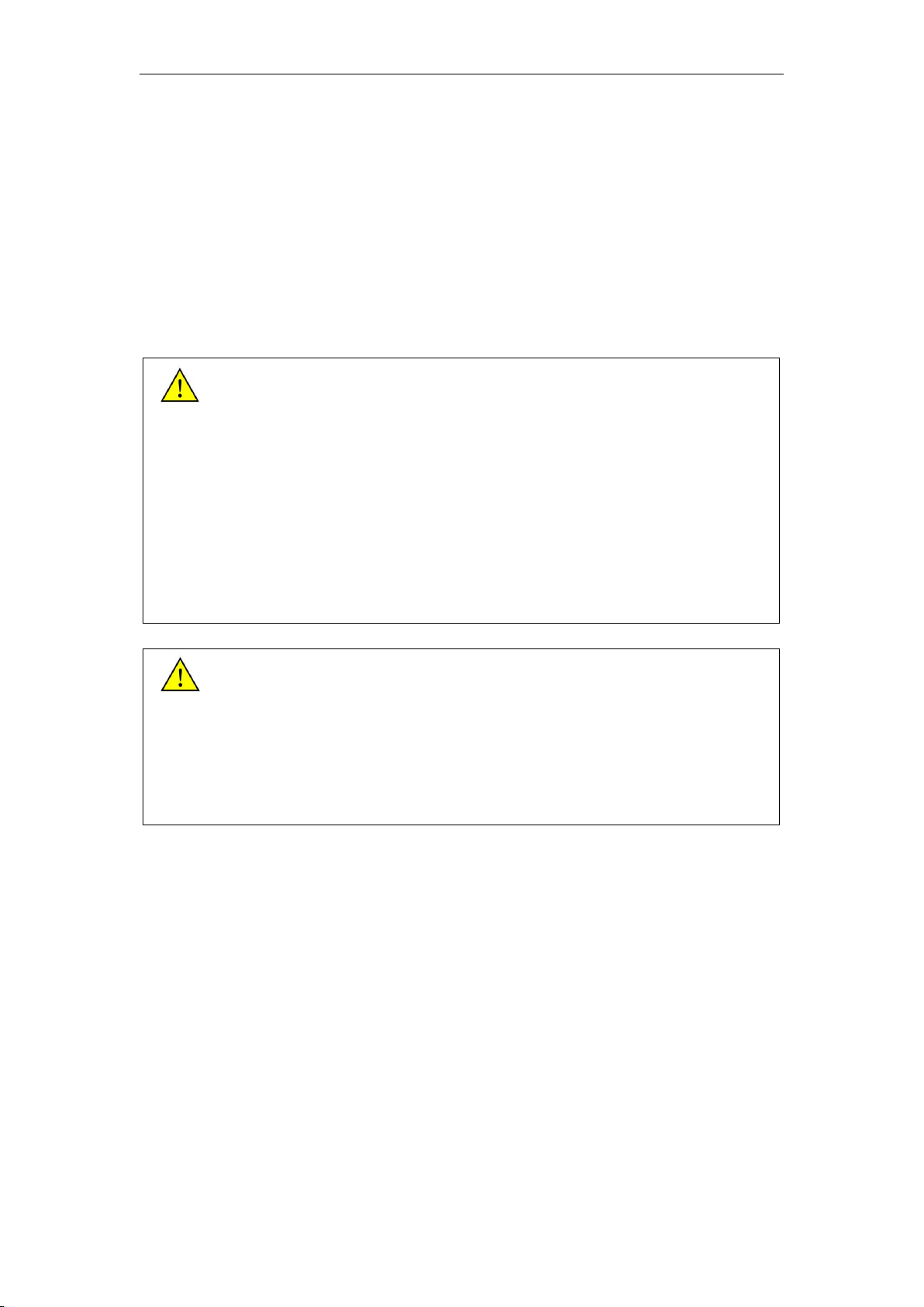
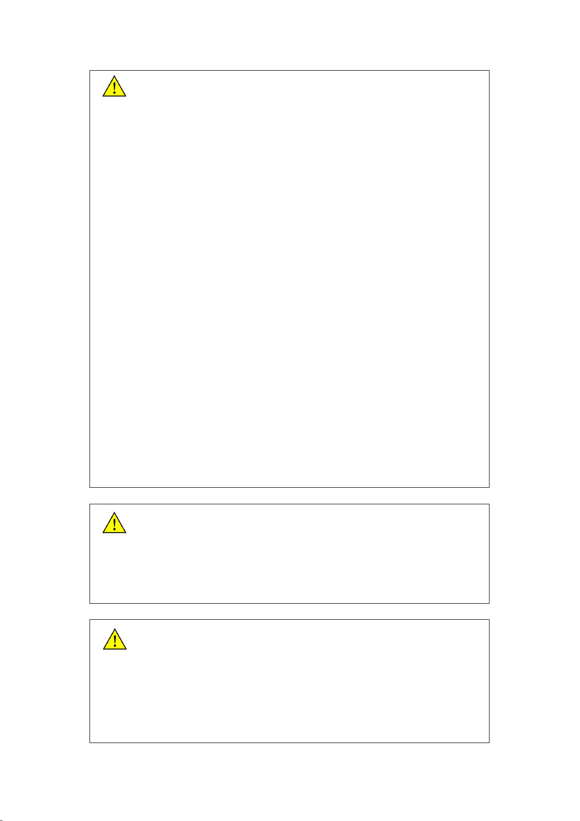
1.2 Safety instruction............................................................................................................ 2
2 Products Introduction.............................................................................................................5
2.1Household PV off-grid Power Generation System Introduction.........................5
2.2 Product Introduction.......................................................................................................6
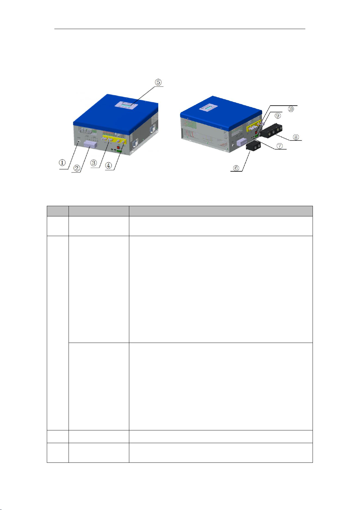
2.2.1 Appearance Introduction.................................................................................... 6
2.2.2 Production Dimensions....................................................................................... 7
3 Inverter & Controller Unpacking Installation................................................................ 9
3.1 Unpacking Inspection.................................................................................................... 9
3.2 Prepare Installation Tools.......................................................................................... 10
3.3 Hanging-mounted Installation...................................................................................10
3.4 Electrical connection................................................................................................... 12
3.4.1 PV Input Connection......................................................................................... 13
3.4.2 AC Input Connection......................................................................................... 14
3.4.3 Battery Connection............................................................................................ 18
3.4.4 AC Output Connection..................................................................................... 20
3.4.5 Communication Ports Connection................................................................23
4 Commissioning........................................................................................................................25
4.1 Electrical Connection Inspection before Commissioning.................................25
4.2 Charging Commissioning........................................................................................... 25
4.2.1 PV Charging Commissioning.......................................................................... 25
4.3 Liquid crystal operation instructions.......................................................................29
4.3.1 All-in-one LCD display...................................................................................... 29
4.3.2 LIQUID crystal display interface.................................................................... 30
4.3.3 CONTENTS of LCD display............................................................................ 31
4.3.4 Liquid crystal function information................................................................ 33
5 Common troubleshooting and maintenance...............................................................42
5.1 Troubleshooting............................................................................................................ 42
5.2 maintenance...................................................................................................................54
6 Appendix A technical parameters....................................................................................55
7 appendix B................................................................................................................................ 59
8 Appendix C................................................................................................................................. 60


1 Safety Instruction
1.1 Safety identification
The following safety symbols may be used in this manual, and the
meanings are shown in below:
Safety Symbol
Meaning
Danger
Indicates that if safety warnings are ignored, serious
accidents may result in personal injury; Pay attention to the
polarity of the connection, do not connect wrong, there is a
risk of damage.
Warning
Means that it may lead to serious accident of
injuries, equipment serious damage or main
business interruption, if safety warning is ignored.
Notice
Means that it may lead to moderate accident of
injuries, equipment moderate damage or part of the
business interruption, if safety warning is ignored.
Note
Means that the content is additional information.
Inverter&Controller related symbol:
Symbol
Meaning
Direct current (DC)
Alternating current (AC)
Protecting Earthing (PE)
Refer to relevant instructions
Can't discard inverter together with domestic
garbage
Beware of dangerous high-voltage. Be careful
during operation.!
CE certification mark. It means that
Inverter&Controller complies with the requirements
of CE certification.
For the electrical and electronics equipment, safety relates to the
whole process of installation, commissioning, operation and
maintenance. Therefore, incorrect use or operation would damage the

2
life and personal security of operating person or the third party, and
inverters.
In order to reduce casualties, damage of inverter&controller and
other equipment, user or operating person should strictly abide by all the
safety information tips of danger, warning and notice which are in the
process of operating and maintaining
1.2 Safety instruction
Warning!
All the installation operation on the machine must be completed by
the professional and technical personnel. The professional and
technical personnel shall:
- Passed specialized training.
- Please read this manual and master the operation of the relevant
security matters completely.
If not in accordance with the manual installation and operation of
the machine is damaged .It will not in the scope of the warranty.
○
1Before installation
Notice!
When you receive the product, please check the damage of the
whole machine during the transportation. If you find any problems,
please contact Supplier (Supplier) or transportation company
immediately
○
2Installing
Ensure inverter& controller NOT have electrical connections and
electricity before installing.

Warning!
If inverter damage caused by the following circumstances will be
beyond the warranty scope of our company.
●The PV array configuration should ensure the max. short-circuit
current of DC side within the allowable range of inverter &
controller, otherwise it may cause irreversible damage to inverter
& controller.
●The PV array configuration should ensure each PV string open
circuit voltage NOT exceed 140V, otherwise it will cause
irreversible damage to inverter & controller.
●Improper installation environment will affect performance of
inverter & controller and may cause damage to the device.
●Do NOT install the device in flammable or explosive place, or
store with flammable and explosive articles.
●Do NOT install the device in an explosive place
●Do NOT install the device in areas where lightning strikes may
occur
●Do not install the device in place where have much salt fog
●During running the device, please ensure good ventilation.
●Inverter should be installed erectly, and ensure the heat sink, fans
etc. are without shelter.
Electrical connection:
Warning!
●All the operation and wiring work should be operated by
professional electrical or mechanical engineer.
●Please do not close any circuit breakers until all devices are fully
connected
Notice!
●All electrical installation must comply with local and national
electrical installation standards.
●In order to ensure the safe operation, require proper earthing, use
appropriate size conductor and provide necessary short circuit
protection.

4
●Cable connection must select the appropriate specifications, firm
connection and good insulation.
○
3In operation
Danger!
●Please do NOT open the device cover when the device is with
electricity!
○
4Repair
Danger!
Maintenance work should be carried out by professional
maintenance technicians.

2 Products Introduction
2.1Household PV off-grid Power Generation System Introduction
Household PV off-grid power generation system consists of PV
array、solar mounting structure、storage battery、Grid(Diesel
Generator)、PV off-grid inverter with controller and conventional
household loads. Use PV solar panel transform solar energy into
electrical energy, meanwhile use solar controller store electrical energy
into battery, inverter can transform battery’s DC power into single phase
AC power to drive household loads work. To meet the power demand of
customers in areas without electricity and poor power.
This system can meet the demands of electric power in the areas
that without grid electricity or lack of electricity.
Meanwhile, in the area of having Grid power and Diesel Generator
input, if grid power is not stable or want to control cost of diesel
generator, the system can manage power automatically, which ensure
household loads work regularly and reduce use-cost.
Figure 2-1Diagram of household PV off-grid power generation system

6
2.2 Product Introduction
2.2.1 Appearance Introduction
Figure 2-2Appearance of inverter & controller
Diagram2-1Information of inverter & controller appearance
No.
Name
Description
1
Overload
protection device
Overload protection reset
2
AC Input
Common machine: AC input is connected to power grid or
diesel generator (L is AC source fire line, n is AC source
zero line, PE is grounding protection; voltage between L
and N is 230VAC).
American Standard Machine: AC input is connected to
power grid or diesel generator (L1 is AC source live wire 1
phase, L2 is AC source live wire 2 phase, n is AC source
zero line; voltage between L1 and L2 is 230VAC, voltage
between L1 and N is 115VAC, voltage between L2 and N
is 115VAC).
AC Output
Common machine: AC output connection load (L is output
live line, n is output zero line, PE is grounding protection).
American Standard Machine: AC output connection load
(L1 is output live wire 1 phase, L2 is output live wire 2
phase, n is output neutral line, PE is grounding
protection; voltage between L1 and L2 is 230VAC,
voltage between L1 and N is 115VAC, voltage between L2
and N is 115VAC).
3
PV Input
Input terminals,connect with PV array.
4
Battery
Terminals
Connect battery array.

5
LCD display
Display current working status and parameter modify
functions.
6
Protection cover
of terminals
Protection cover of terminal “AC IN” and “Load”, protect
terminals from corrosion and person from electric shock
7
Communication
Interface
RS485 communication function, can connect
communication transform equipment, to monitor the
working status of the whole system.
8
Protection cover
of terminals
Protection cover of terminal “PV” and “BAT”, protect
terminals from corrosion and person from electric shock
9
Control
Interface
TB is the connecting interface of temperature sensor, be
used to monitor battery’s temperature to prolong battery
lifespan;NO、NC is dry contactor control terminal, can
connect diesel generator and control its start.
10
Power Button
Inverter & Controller ’s power button
2.2.2 Production Dimensions
Figure 2-3Dimension of inverter &controller(mm)
Diagram 2-2 Inverter & Controller Size and Weight Sheet

8
No.
Model No.
W
(mm)
H
(mm)
D
(mm)
Net Weight
(kg)
1
JNF3KLF24V-V2
JNF3KLF24V-A-
V2
370
440
190
29
2
JNF3KLF48V-V2
JNF3KLF48V-A-
V2
370
440
190
30
3
JNF4KLF48V-V2
JNF4KLF48V-A-
V2
370
440
190
31
4
JNF5KLF48V-V2
JNF5KLF48V-A-
V2
370
440
190
33
In order to meet the voltage requirements of different national power grids, the
all-in-one machine models are divided into two series: ordinary and American
Standard
General machine model: JNF__ KLF__ V-v2 series
American Standard Machine Model: JNF__ KLF__ V-a-v2 series
The difference between ordinary machines and American standard machines lies
in the different input voltage levels of AC source and the different AC output
voltage levels.

3 Inverter & Controller Unpacking Installation
3.1 Unpacking Inspection
To ensure system installation goes smoothly, please check before
unpacking. Specific inspection items are as follows:
●Check whether the outer packing is in good condition.
●Unpack, and check up the products damage or not.
●Contrast to packing list, to check whether all accessories is correct and
in good condition.
Standard inverter & controller and some common used accessories are
as follows, specific models and qty. please check up with installation
list:
Figure 3-1 Inverter & Controller and standard accessories
Diagram 3-1 Inverter & Controller and Accessories sheet
No.
Description
Dispatch status
1
Inverter & Controller
Standard
2
M6*16 cross head combination screw
and matching nut
Standard
3
Expandable screw
Standard
4
SC5-6 Cool pressing terminal
Standard
5
Phoenix terminal
Standard
6
SC35-6 Cool pressing terminal
Standard
7
Installation list
Standard

10
8
Quality Certification
Standard
9
User manual
Standard
3.2 Prepare Installation Tools
Inverter & controller installation and wire installation tools are as
follows,installation workers need to use tools as per request of follow
sheet without any mistake.
Diagram 3-2 Installation Tools List
Diagram
sketch
Name
Recommended
spec.
Function
Flat
screwdriver
Φ2
Use for cable installation
Cross
screwdriver
Φ4
Use for cable installation
hydraulic tongs
M2.5~M8
Use for cool pressing
terminal installation
Crimping Pliers
M2.5~M8
Use for connecting with
battery terminals
adjustable
spanner
300mm
Use for nut assembly,
inverter& controller
installation
Impact drill
Φ8
Use for drilling hole and
inverter & controller
installation
Wire stripping
pliers
M1.5~M8
Use for connecting PV
cable
Hammer
6Pounds
Use for striking expansion
screws
3.3 Hanging-mounted Installation
Inverter & Controller’s hanging-mounted installation should be
controlled the angle range of vertical and horizontal be 80°-90°, as
follows:

Figure 3-2 Hanging-mounted Installation Demonstration Figure
Step 1: Please check the installation situation, to ensure its convenient
installation and heat dissipation, we suggest leave up and down
gap >=100cm, right and left side >=100cm, front side >=30cm.
Step 2: Mark up the installation holes, drill 4 holes accordingly
(Diameter: 10mm; Depth: 80mm).
As shown in the figure:
Figure 3-3 Hang position diagram
Follows are wall hanging sizes of different inverter & controller models:
Diagram 3-3 Fixed position sizes chart
Position size
Model of Inverter & Controller
L:349mm
H:316mm
JNF3KLF24V-V2 JNF3KLF24V-A-V2
JNF3KLF48V-V2 JNF3KLF48V-A-V2
JNF4KLF48V-V2 JNF4KLF48V-A-V2
JNF5KLF48V-V2 JNF5KLF48V-A-V2
Step 3:Refer to follow installation method to finish the installation:

12
Figure 3-4 Installation operation diagram
3.4 Electrical connection
Carry on electrical connection when installation conditions are
satisfied. Please ensure electrical connection’s air-switch and cable
model can meet system demands, specific selection model sheet are as
follows:
Diagram 3-4 Selection of Inverter & Controller breaker and cable model
Breaker selection
Cable selection(AWG)
Inverter & Controller
model
PV
AC
BAT
Loa
d1
Loa
d2
PV
AC
BAT
Load
1
Load
2
JNF3KLF24V-V2
JNF3KLF24V-A-V2
50
32
125
16
16
10
12
3
13
13
JNF3KLF48V-V2
JNF3KLF48V-A-V2
50
32
80
16
16
8
10
6
13
13
JNF4KLF48V-V2
JNF4KLF48V-A-V2
63
32
100
20
20
6
9
5
12
12
JNF5KLF48V-V2
JNF5KLF48V-A-V2
63
32
100
25
25
6
7
4
10
10
Note: AWG of cable selection means American Standard, indicating
diameter of cable
1,Drill hole around 80mm deep
by impact drill at the positioning
point of the wall and the panel,
hammer the expansion bolt into
hole.
2,Unscrew the nut, hang up
inverter & controller, screw-up nut
by adjustable spanner, complete
hang-up installation

3.4.1 PV Input Connection
Step 1: Do the following inspections before PV side terminal
connecting:
Please make sure system’s DC air-switch on PV side is in off state,
before connecting with PV array.
Please ensure PV array’s polarity be matched with PV connectors’
polarity, to avoid inverter & controller damage.
Make sure PV array’s max open-circuit voltage must less than
inverter & controller’s max allowable input voltage.
Step 2: Make PV connectors and cable connecting of PV input side,
please according to following steps:
4、Screw M6*16 and M6 nut are used to fix the cable inserted into
the protective cover corresponding to the terminals connected to
PV+ and PV- screen printing in the case, then tighten the
1、Use stripping
pliers to strip the
cable for 10mm
2、Press the upper
terminal with line
clamp
3、Insert the
pressed cable into
the protective

14
Figure 3-5 schematic diagram of photovoltaic terminal production and connection
Step 3: During cable connecting of PV input side, insert PV cable of PV
array into auto Air-switch respectively according to positive pole and
negative pole; then insert the two cables which made in Step 2 into
Air-switch separately.
Step 4: Check whether PV connecting is correct and firm.
The cable connection diagram of PV input side is as follows:
Figure 3-6 PV Input Side Cable Connecting Diagram
3.4.2 AC Input Connection
Inverter & Controller can accept two kinds of AC power input, one is
single phase grid power, and another is single phase diesel generator
power. Please select corresponding connection mode according to the
specific connection.
3.4.2.1Grid Power Input connection
Please make sure Grid power in off state.
Step 1: Please according to follow methods, making Grid power side
cable connection and connectors.
1、Use stripping pliers to strip
the cable for 10mm
2、Insert the finished cable
into the protective cover

Ordinary machine: AC IN screen printing for L, N, PE
American standard machine:American standard machine: AC IN screen for L1, L2, N
Figure 3-7 Grid Power Side Connectors Making and Cable Connecting Diagram
Step 2:Conduct wiring at the input end of the power grid:
Common machine:Connect the cables at the end of the power grid to the
air switch according to L (fire line) and N (zero line) respectively, and PE
ground; Keep ac side space open and off.
3、Screw down the cable inserted into the
protective cover corresponding to the
terminal connected to the box AC IN screen
printing and tighten it with a word screw
driver, then tighten the protective cover on
the cover to complete the terminal
connection of the power grid

16
American standard machine:Connect the cables at the end of the grid to
the air switch according to L1 (fire line 1 phase), L2 (fire line 2 phase)
and N (zero line) respectively. Keep ac side space open and off.
Step 3: Then connect the other end of the cable made in Step 1 to the
open space and check whether the connection is correct and firm.
The wiring diagram of the input end of the power grid is as follows:
Figure 3-8 Grid Input Side Cable Connecting Diagram
3.4.2.2Diesel Generator Connection
Please ensure inverter & controller in power off state.
Step 1: Refer to diesel generator’s user manual, to find its start mode is
NO (normally open) or NC (normally close).
Step 2:If diesel generator’s start mode is NO (normally open), then
insert diesel generator’s NO terminal into inverter & controller’s NO
terminal accordingly; If diesel generator’s start mode is NC (normally
close), then insert diesel generator’s NC terminal into inverter&
controller’s NC terminal accordingly; Ensure the connecting of NO-NO
or NC-NC is correct, specific connection mode, please refer to follows
for details.
This manual suits for next models
7
Table of contents
Other Jntech Inverter manuals

Jntech
Jntech JNP75KH User manual

Jntech
Jntech JNP Series User manual

Jntech
Jntech JNP1K1L-V5 Original operating instructions

Jntech
Jntech JNP1K1L-G User manual

Jntech
Jntech JNP22KH-V5 User manual

Jntech
Jntech JNP370LS-V1 Original operating instructions

Jntech
Jntech JNP550L-V5 Original operating instructions

Jntech
Jntech JNP75KH-V3 User manual

Jntech
Jntech JNP550L-V5 Original operating instructions

Jntech
Jntech JNF1KLF-A/24V User manual