Volvo 2004 S40 Quick start guide

2004
VO LVO
WI RI NGDI AGRAM S40(04-)/V50
TP 3974202

© Volvo Car Corporation
Vehicles with SRS (Airbag)/SIPS bag/IC
(Inflatable Curtain)
Warning!
Extra caution must be exercised when working on vehicles equipped with SRS/SIPS
bag/IC in order to avoid:
1. Personal injuries when performing repair work.
2. Damage or malfunction of the SRS/SIPS bag/IC system.
Work involving the SRS/SIPS bag/IC systems or other components in the vehicle that may
affect the SRS/SIPS bag/IC systems must always be performed by an authorized Volvo
workshop.
In case of doubt, consult the SRS and SIPS bag/IC service manual.
Is the vehicle equipped with SRS/SIPS bag/IC ?
Vehicles with SRS are most easily recognized by the letters SRS in the center of the steering
wheel. If the vehicle also has a passenger side airbag, the letters SRS are stamped on the
dashboard above the glove compartment. SRS vehicles from 1993 and onward also have
explosive seat belt tensioners. SIPS bags are only installed on SRS vehicles from 1995 and
onward. SIPS bag decals are located on the windshield and seat compartment. Vehicles with
IC can be recognized by the letters IC on the C/D panel (4 door) or the B panel (5 door).
General recommendations
• Be especially careful when working on or around SRS, SIPS, and IC components.
• Make sure that no wires are pinched, frayed, or pierced.
• Never install accessories by the sensors.
• Where applicable, work on the steering wheel, steering shaft, or steering gear must be done
in accordance with the methods in the SRS section of VADIS.
• Certain components of the aforementioned systems must be grounded while working. Read
the appropriate sections in VADIS.
• Install no accessories in the areas between the A and B posts, the B and C posts, and the C
and D posts.
Test terminal
Data link connector in the passenger compartment.
Changes introduced up to October 2003
Any changes made to the vehicles after this date are not included in the
manual. If necessary refer to service bulletins.
Volvo models are sold in versions adapted for different markets. These
adaptations depend on factors such as legal requirements, taxation, and
market demands.
This manual may therefore include illustrations and text that do not apply to
the vehicles in your country.

TP3974202 S40 (04-)/ V50 2004
Vehicles with SRS (Airbag)/SIPS bag/IC
(Inflatable Curtain) ......................................................... 2
Abbreviations................................................................. 5
How to use the wiring diagrams 1:2............................... 6
Electrical distribution 1:2................................................ 8
Fuses
Engine compartment distribution box F1-F8................. 10
Engine compartment distribution box F9-F18............... 11
Engine compartment distribution box F20-F32............. 12
Engine compartment distribution box F33-FH1 ............ 13
Central Electronic Module (CEM) F43-F52................... 14
Central Electronic Module (CEM) F53-F66................... 15
Central Electronic Module (CEM) F67-F86................... 16
Battery, PF1-PF2.......................................................... 17
Relays
Ignition switch and relays............................................. 18
Engine compartment distribution box R2-R14............. 19
Central Electronic Module (CEM) R15-R18................. 20
Relays - soldered......................................................... 21
Ground connections
Overview...................................................................... 22
31/3 - 31/10 ................................................................. 23
31/11 - 31/66 ............................................................... 24
31/67 - 31/84 ............................................................... 25
31/88 - 31/114 ............................................................. 26
31/115 - Ground connections in chassis...................... 27
Control modules
Overview of locations................................................... 28
Overview of designations............................................. 29
Central Electronic Module (CEM) 1:2 .......................... 30
Low speed CAN data communication 1:2.................... 32
LIN data communication 1:2........................................ 34
High speed CAN data communication......................... 36
Data communication MOST......................................... 37
Start Control Module (SCU)......................................... 38
Accessory Electronic Module (AEM) ........................... 39
Group 23 Fuel system
Engine management system, 5-cyl 1:2........................ 40
Engine management system, 5-cyl Turbo 1:2 ............. 42
Engine management system, Diesel 1:2 ..................... 44
Emission control, 5-cyl................................................. 46
Emission control, 5-cyl Turbo ...................................... 47
Group 26 Cooling system
Cooling fan................................................................... 48
Cooling fan Diesel........................................................ 49
Group 27 Engine control
Cruise control................................................................ 50
Cruise control, Diesel.................................................... 51
Group 32 Generator and voltage regulator
Power supply ............................................................... 52
Power supply, Diesel ................................................... 53
Group 33 Starting system
Starting system ............................................................ 54
Starting system, Diesel ................................................ 55
Group 35 Lighting
High and low beam ...................................................... 56
High and low beam (Bi-Xenon).................................... 57
Manual beam length adjustment.................................. 58
Automatic head light leveling (Bi-Xenon)..................... 59
Position/parking lights,Tail lights.................................. 60
Position/parking lights, Tail lights (Bi-Xenon)............... 61
Fog lights ..................................................................... 62
Fog lights LHD, Japan ................................................. 63
Brake lights .................................................................. 64
Reversing lights ........................................................... 65
Interior lighting 1:2 ....................................................... 66
Instrument and control illumination .............................. 68
Follow-me-home lighting.............................................. 69
Auxiliary light................................................................ 70
Group 36 Additional electrical equipment
Rain Sensor ................................................................ 71
Direction indicators and warning lights ........................ 72
Direction indicators and warning lights (Bi-Xenon) ...... 73
Windshield wiper/washer ............................................. 74
Headlight washer ......................................................... 75
Wiper/washer, rear window ......................................... 76
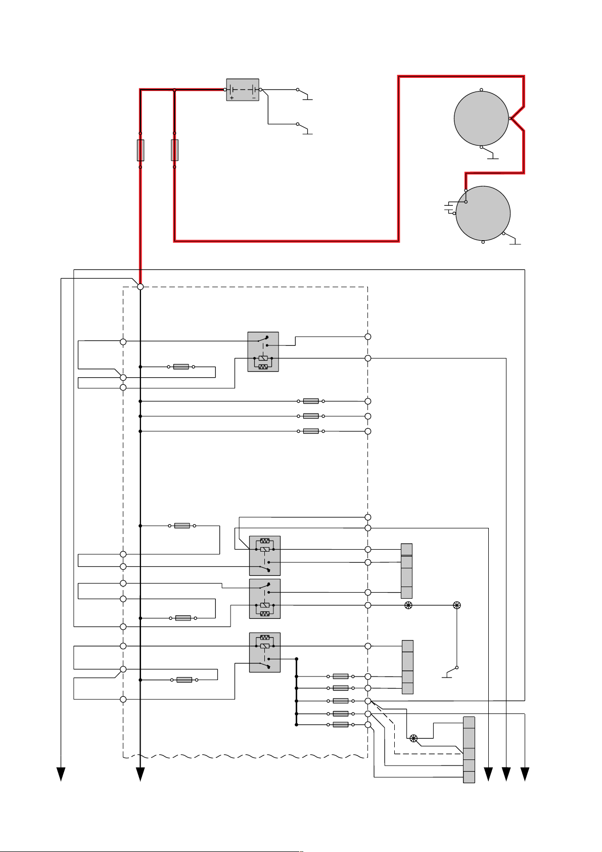
Horn ........................................................................ 77
Electronic immobilizer / Steering Column Lock
Module (SCL)............................................................... 78
Anti-theft alarm ............................................................ 79
Accessory Electronic Module (AEM)............................ 80
Group 37 Wiring and fuses
Diagnostics system...................................................... 81
12V outlet..................................................................... 82
Towbar cable harness, 4-pin........................................ 83
Towbar cable harness, 7-pin........................................ 84
Towbar cable harness, 13-pin ..................................... 85
Group 38 Instruments
Seat belt reminder ....................................................... 86
Driver information module............................................ 87
Group 39 Other
Audio 1:2 ................................................................... 88
Cellular phone 1:2 ....................................................... 90
Multimedia & traffic information .................................. 92
Subwoofer.................................................................... 93
Handsfree .................................................................... 94
Table of Contents 1:2

TP3974202 S40 (04-)/ V50 2004
Group 43 Transmission
Automatic transmission AW55-51................................ 95
Shift interlock ............................................................... 96
Transmission M66 ....................................................... 97
Group 59 Brake system
Brake control system ................................................... 98
Brake control system & STC........................................ 99
Brake control system & DSTC................................... 100
Group 64 Steering
Electronic power steering .......................................... 101
Group 83 Doors and openings
Central locking, front doors ....................................... 102
Central locking, rear doors......................................... 103
Central locking, trunk lid/tailgate................................ 104
Child safety lock......................................................... 105
Central locking, fuel filler flap..................................... 106
Signal receiver, remote-control, central locking......... 107
Power windows, front doors....................................... 108
Power windows, rear doors ...................................... 109
Power sunroof............................................................ 110
Group 84 Exterior decorative elements etc.
Power door mirrors .................................................... 111
Heated door mirrors................................................... 112
Heated rear window................................................... 113
Group 85 Interior equipment
Power driver’s seat with memory function, left .......... 114
Power driver’s seat with memory function, right ........ 115
Power seat, LHD left.................................................. 116
Power seat, LHD right................................................ 117
Power seat, RHD right............................................... 118
Power seat, RHD left ................................................. 119
Heated seats ............................................................. 120
Group 87 Climate controls
Parking heater, auxiliary heater ................................ 121
Climate control system 1:2......................................... 122
Climate control system, Diesel 1:2............................. 124
Climate control system PTC element......................... 126
Relay, electric engine heater ..................................... 127
Group 88 Internal equipment
Supplemental Restraint System (SRS) 1:2 ............... 128
Rearview mirror with Auto-dimming........................... 130
Connectors............................................... 131
Junction points ........................................150
Cable harness routing in vehicle
Engine harness, Gasoline 5 cyl .................................157
Engine harness, Gasoline 5-cyl Turbo........................157
Engine compartment harness.....................................158
Dashboard harness ....................................................159
Infotainment harness ..................................................160
Floor harness..............................................................161
Roof harness, S40 ......................................................162
Roof harness, V50 ......................................................163
Tunnel harness ...........................................................164
Driver’s door harness..................................................165
Passenger door harness.............................................165
Right rear door harness ..............................................166
Left rear door harness ................................................166
Trunk lid/tailgate harness, S40 ...................................167
Trunk lid/tailgate harness, V50 ...................................167
Component illustrations ..........................168
Index ......................................................... 208
List of components 1:4
Table of Contents 2:2

TP3974202 S40 (04-)/ V50 2004 5
Explanations
Abbreviations
Groups
Group 23 = Fuel system
Group 26 = Cooling system
Group 27 = Engine controls
Group 32 = Generator and voltage regulator
Group 33 = Starting system
Group 35 = Lighting
Group 36 = Additional electrical equipment
Group 37 = Wiring and fuses
Group 38 = Instruments
Group 39 = Other
Group 43 = Transmission
Group 59 = Brake system
Group 64 = Steering
Group 83 = Doors and openings
Group 84 = Exterior decorative elements etc.
Group 85 = Interior equipment
Group 87 = Climate controls
Group 88 = Internal equipment
Ignition switch symbols
X=Accessories(audioposition)
S=Powereduponinsertionofkey
15 = Contact remains connected during
start
15l = Contact is broken while starting
30 = Constant power from the battery
50 = Start
Countries/Markets
A=Austria
AUS = Australia
B=Belgium
CDN = Canada
CH = Switzerland
D=Germany
DK = Denmark
E=Spain
EU/OS = Markets outside USA and Canada
FIN = Finland
GB = Great Britain
ISR = Israel
J=Japan
KOR = Korea
N=Norway
NL = Netherlands
S=Sweden
USA = United States of America
WEU = Western Europe
Other
AUDIO = Audio system
AUTO = Automatic transmission
DIESEL = Diesel
DSTC = Dynamic Stability Traction Control
ECC = Electronic climate control system
E.E = Early edition
EXT. X = Extended X-feed
HISPEED = High speed data bus
L.E = Late edition
LHD = Left-hand drive
LOSPEED = Low speed data bus
MAN = Manual transmission
MMS = Mass Movement Sensor
PCL = Power Child Lock
GASOLINE = Gasoline
RHD = Right-hand drive
RTI = Road Traffic Information
SRS = Airbag
STC = Stability Traction Control
T=Turbochargedengine
W/O = Without
4CYL = 4-cylinder engine
5CYL = 5-cylinder engine
Colors
BK = Black
BN = Brown
BU = Blue
GN = Green
GY = Gray
LGN = Light Green
OG = Orange
PK = Pink
RD = Red
VT = Violet
WH = White
YE = Yellow

TP3974202 S40 (04-)/ V50 2004 6
The descriptions below apply in general
to all wiring diagram manuals, although
not all sections are necessarily con-
tained in this manual.
How to use the wiring diagrams 1:2
A. Component designation
Every component has a component designation that
consists of two parts.
The first part is a type number that describes the
type of component in question, for example 3/xx.
The second part of the designation is a serial num-
ber, e.g. x/2.
Togeth er, thi s co nst itu tes a c om pon ent d esi gna tio n,
e.g. 3/2.
At the end of the manual is a list of components,
where, with the help of the component designation,
you can read off the name of the component, for
example, 3/2 = light switch.
List of type numbers
The list shows which type of component that respec-
tive type numbers refer to, for example, 3/x = switch,
6/x = electric motor, etc.
1Battery
2Relay
3Switch
4Controlmodule
5Driverinformationmodule
6Electricmotor
7Sensor
8Actuator
9Heatingelement
10 Lamp
11 Fuse
15 Electrical distribution rail/box
16 Audio
17 Service/diagnostics
18 Contact reel
19 Meter
20 Ignition component/shunt
27 Optics
31 Ground connection
63 Junction point
64 Connector
B. Junction points
The wiring diagrams contain numbered junction
points, e.g. 63/352.
This manual contains a section with a list of junction
points. This list shows all the components that are
connected to each junction point.
The location of the junction points is shown in the
"Cable harness routing in vehicle" section.
C. Connectors
Connectors provide a bridge between two cables
harnesses and are described in the "Connectors"
section.
D: Electrical distribution
Operation of the fuses and relays is shown in the
"Electrical distribution" section.
E. Data communication
To d a y’ s c a r s c o n ta i n s C A N a n d M O S T n e t w or k s t h a t
transfer information. Connections to these networks
are not shown in their entirety in the respective wir-
ing diagram. Complete information on CAN and
MOST communication is found in the section "Con-
trol modules".
F. Abbreviations
A number of different abbreviations are used in the
manual. These are explained in the section "Abbre-
viations".
G. Component location
There is a section at the end of the manual in which
the appearance and location of components is
described in numerical order.

TP3974202 S40 (04-)/ V50 2004 7
How to use the wiring diagrams 2:2
List of symbols
= System voltage
= Ground connection
via wiring
= Ground connection on
component/chassis
= Screened wire
= Junction point
= Twisted cable
= Electrical connection
= Variant
= CAN communication
= CAN high data signal
(CAN H)
= CAN low data signal
(CAN L)
= MOST communication
= LIN communication
= DIN cable, coaxial cable,
etc.
= Data communication
= CAN communication
= Connection with distribution
box
= Further connection to...
= Connector between
cable harnesses
= Connector connected
to component
CAN
1
1
G
AEC F B D
10/17-18
BK
GN-BK
CAN
CAN
63/211
31/11 31/12
F:14
F:16
D:14
D:15
A:6
A:8
TCM
4/28 30+
F18
2
11
2
F4
MAN
63/53
MAN
GN-YE
GN-YE
64/90
10
31/52
E:14
4/56
CEM
3/10
1
2
GN-BK
GN-BK
BK
V50
10/55
10/48
BK
V50
BK
F79
2
1
LIN
15/31
C:45
E:21
E:22
GN-BK
S40 S40
BK
BK
2/80
R2
TAIL
FOG
BACK
10/18
10/18
A:4
C:4
C:2
A:2
TAIL
FOG BACK
GND GND2
TURN STOP
10/55
10/17
A:2
A:4
TAIL
FOG
BACK
GND
GND2
TURN
STOP
10/48
TURN
STOP
A:2A:3 C:3 C:1
A:4
TAIL
FOG
BACK
10/17
C:2
C:4
TURN
STOP
A:2 A:3C:1C:3
A:4
C:4 C:2
A:1 C:1C:3C:4
C:2C:1
A:3
C:3
V50
V50
S40S40
LIN
3/156
64/90
A:7 WH-RD RD
33
64/111
2
A:2
LIN
3/155
GSM
WH-RD
AUTO
RD-YE
RD-BU
GN-BK
UP
UP
UP UP

TP3974202 S40 (04-)/ V50 2004 8
Electrical distribution 1:2
Overview
EDC
31/114
63/120
BK
BK
63/121
BK
RD
1
F36
F34
F33
F35
F32
3
2
5
5
3
12
12
35
35
12
F10
F17
F14
GY
BK-WH
GN-BU
2/32
R14
R5
2/142
R13
2/35
R10
2/82
F12
F13
F24
F9
RD-OG
RD-OG
RD-BK
RD-GN
RD-OG
RD-OG
A
15/31
6/25
50
31
M30
A:3
B:1
6/26
B+
31
L
G
B:1
A:1
RD
RD
12V BK
31/3
1/1
BK
31/4
PF2 PF1
RD
RD-OG
40
14
39
64/90=15/31A
64/90=15/31A
11
6
4
BK-RD
GY
GN-RD
64/90=15/31A
41
12
21
BK-BU
GN-BU
GN-BU
GN-YE
GN-BU
GN-YE
B
DIESEL GN-BU PETROL
2
11
2
35
GN-YE
GN-YE
63/13
GN-YE
5 CYL T
W/O T

TP3974202 S40 (04-)/ V50 2004 9
Electrical distribution 2:2
Overview
RD-WH
RD-BK
RD-GN
RD-OG
RD-BU
RD-OG
RD-BU
2
1
3
5
3
1
5
2
3
1
5
2
2
5
3
1
CAN
CEM
4/56
LIN
BK-YE
G:11
CDE
G:18
E:9
E:30
3/1
30
15X
5
50 S
B:7
A:42
A:15
A:30
A:17
B:5
B:2
B:1
B:3
GY-BK
RD-GN
YE
GN-WH
64/111
5
G:9
E:22
E:23
E:20
E:21
RD-YE
RD-BU
RD-WH
RD-OG
RD
RD
BK-BU
2/182
R9
2/34
R4
2/22
R11
R2
2/17
F20
F26
F3
F30
F31
F2
F16
F6
F23
F4
F18
F27
F29
F11
F8
F7
F1
F5
F21
A
RD-OG
GY
BK-WH
GN-BU
15/31
BK-RD
13
64/90=15/31A
RD
23
64/90=15/31A
RD
17
64/90=15/31A
BK-YE
18
GN-YE
PETROL
GN-BU
DIESEL
B

TP3974202 S40 (04-)/ V50 2004 10
F30
F11
F8
F17
F15
F7
F13
F16
F9
F18 F14
F12 F10
F6
F5
F4
F3
F2
F1
F24 F21 F20 F22
F31
F25
F32
F33
F34
F35
F36
F29
F28 F27 F26 F23
F19
Fuses
Engine compartment distribution box F1-F8
15/31 Engine compartment distribution box
No. Fuse function via A
F1 4/71 Cooling fan control module - 50
F2 6/71 Electrical Power Steering Module (EPS) - 80
F3 2/193 Relay, comfort functions
F45 Fuse in the Central Electronic Module (CEM)
F48-F49 Fuses in the Central Electronic Module (CEM)
F60-F61 Fuses in the Central Electronic Module (CEM)
F62-F63 Fuses in the Central Electronic Module (CEM)
F68-F69 Fuses in the Central Electronic Module (CEM)
F84-F85 Fuses in the Central Electronic Module (CEM)
-
2/193
2/193
2/193
-
2/193
-
60
F4 2/63 Relay, high beam
4/56 Central Electronic Module (CEM)
8/134 Solenoid, reverse interlock, manual
F58-F59 Fuses in the Central Electronic Module (CEM)
F74 Fuses in the Central Electronic Module (CEM)
F77 Fuses in the Central Electronic Module (CEM)
-
-
4/56
2/63
-
-
60
F5 9/41 PTC element, Diesel - 80
F6 4/109 Glow plug control module - 60
F7 4/16 Brake Control Module (BCM), pump - 30
F8 4/16 Brake Control Module (BCM), valves - 20
continues

TP3974202 S40 (04-)/ V50 2004 11
F30
F11
F8
F17
F15
F7
F13
F16
F9
F18 F14
F12 F10
F6
F5
F4
F3
F2
F1
F24 F21 F20 F22
F31
F25
F32
F33
F34
F35
F36
F29
F28 F27 F26 F23
F19
Fuses
Engine compartment distribution box F9-F18
15/31 Engine compartment distribution box
No. Fuse function via A
F9 2/32 Main relay, engine management system
F32-F36 Fuses in the engine compartment distribution box
-
2/32
30
F10 4/31 Fan control module - 40
F11 2/182 Relay, headlight washer motor
6/104 Pump, high pressure headlight washer
-
2/182
20
F12 2/82 Relay, heated rear window
9/2 Heated rear window
-
2/82
30
F13 6/25 Starter motor 2/35 30
F14 4/110 Trailer Module (TRM) - 40
F16 2/159 Relay, infotainment
16/105 Audio Module (AUD)
F43 Fuse in the Central Electronic Module (CEM)
F64 Fuse in the Central Electronic Module (CEM)
F65-F67 Fuses in the Central Electronic Module (CEM)
-
-
-
-
2/159
30
F17 6/1 Wiper Motor Module (WMM) - 30
F18 2/80 Relay, reversing lights
2/89 Relay, interior lighting
4/56 Central Electronic Module (CEM)
F46-F47 Fuses in the Central Electronic Module (CEM)
F56-F57 Fuses in the Central Electronic Module (CEM)
F79 Fuse in the Central Electronic Module (CEM)
F81-F83 Fuses in the Central Electronic Module (CEM)
F86 Fuse in the Central Electronic Module (CEM)
-
-
-
2/89
-
2/80
-
2/89
40
continues

TP3974202 S40 (04-)/ V50 2004 12
F30
F11
F8
F17
F15
F7
F13
F16
F9
F18 F14
F12 F10
F6
F5
F4
F3
F2
F1
F24 F21 F20 F22
F31
F25
F32
F33
F34
F35
F36
F29
F28 F27 F26 F23
F19
Fuses
Engine compartment distribution box F20-F32
15/31 Engine compartment distribution box
No. Fuse function via A
F20 2/17 Relay, horn
16/10 Horn 1
16/11 Horn 2
-
2/17
2/17
15
F21 4/7 Combustion Preheater Module (CPM) - 20
F23 4/28 Transmission Control Module (TCM)
4/46 Engine Control Module (ECM)
-
-
10
F24 9/38 Heated fuel filter, Diesel 2/42 20
F26 2/35 Relay, starter motor
3/1 Start Control Module (SCU)
4/46 Engine Control Module (ECM)
4/56 Central Electronic Module (CEM)
F44 Fuse in the Central Electronic Module (CEM)
F51-F54 Fuses in the Central Electronic Module (CEM)
F73 Fuse in the Central Electronic Module (CEM)
3/1
4/56
3/1
3/1
3/1
3/1
3/1
15
F27 8/3 Electromagnetic clutch, climate control system 2/22 10
F29 2/34 Relay, front fog lights
10/5 Fog light, front left
10/6 Fog light, front right
-
2/34
2/34
15
F30 4/46 Engine Control Module (ECM), Diesel - 3
F31 6/26 Generator, Diesel - 10
F32 8/6-8/10 Injectors, Gasoline - 10
continues

TP3974202 S40 (04-)/ V50 2004 13
F30
F11
F8
F17
F15
F7
F13
F16
F9
F18 F14
F12 F10
F6
F5
F4
F3
F2
F1
F24 F21 F20 F22
F31
F25
F32
F33
F34
F35
F36
F29
F28 F27 F26 F23
F19
Fuses
Engine compartment distribution box F33-FH1
15/31 Engine compartment distribution box
No. Fuse function via A
F33 2/142 Relay, pre-heater, fuel filter, Diesel
6/114 Vacuum pump
7/15 Heated oxygen sensor, front
7/82 Heated oxygen sensor, rear
-
8/84
-
-
20
F34 4/46 Engine Control Module (ECM)
8/77 Control valve, fuel volume, Diesel
8/133 Control valve, fuel pressure, Diesel
20/3 -20/7 Spark plug and ignition coil
8/119
-
-
-
10
F35 2/22 Relay, climate control system
6/67 Pump, fuel leakage control
7/17 Mass airflow sensor (MAF)
8/18 EVAP valve
8/19 Solenoid, variable valve timing, intake
8/28 Turbocharger control valve
8/81 Solenoid, variable valve timing outlet
8/68 Bypass valve, Diesel
8/82 Solenoid, variable turbo geometry, Diesel
8/131 Cut-off valve, expansion tank, Diesel
8/132 Control valve, intake, Diesel
9/32 PTC resistor, oil trap
-
-
-
-
-
-
-
-
-
-
-
-
10 E.E
15 L.E
F36 4/46 Engine Control Module (ECM)
7/51 Accelerator pedal sensor
-
-
10
FH1 10/65 Auxiliary light, front right
10/69 Auxiliary light, front left
2/64 20

TP3974202 S40 (04-)/ V50 2004 14
Fuses
Central Electronic Module (CEM) F43-F52
F37 F42
F86
F64
F65
F43
4/56 Central Electronic Module (CEM)
No. Fuse function via A
F43 16/46 RTI Display
16/60 Phone Module (PHM)
16/107 Media Player Module (MPM)
-
-
-
15
F44 4/9 Supplemental Restraint System Module (SRS) - 10
F45 9/1 Front 12V outlet
9/25 Rear 12V outlet
-
-
15
F46 3/111 Switch unit, lights
5/1 Driver Information Module (DIM)
10/29 Glove compartment lighting
10/97 Courtesy lighting, left
10/102 Courtesy lighting, right
-
-
-
-
-
5
F47 10/22 Ceiling light
10/114 Vanity mirror lighting, left
10/115 Vanity mirror lighting, right
-
-
-
5
F48 2/16 Relay, rear window wiper
2/92 Relay, windshield washer motor
2/93 Relay, rear window washer motor
6/2 Washer pump
6/2 Washer pump
6/32 Rear window wiper motor
-
-
-
2/92
2/93
2/16
15
F49 4/9 Supplemental Restraint System Module (SRS)
7/93 Occupant Weight Sensor (OWS), USA/CDN
-
-
10
F51 10/1 Lamp housing, front left, beam length adjustment
10/2 Lamp housing, front right, beam length adjustment
4/112 Control module, gas discharge lamp master, left
4/113 Control module, gas discharge lamp slave, right
9/41 PTC element, Diesel
-
-
-
-
-
10
F52 4/16 Brake Control Module (BCM) - 5
continues

TP3974202 S40 (04-)/ V50 2004 15
F37 F42
F86
F64
F65
F43
Fuses
Central Electronic Module (CEM) F53-F66
4/56 Central Electronic Module (CEM)
No. Fuse function via A
F53 6/71 Electrical Power Steering Module (EPS) - 10
F54 4/28 Transmission Control Module (TCM)
6/26 Generator
-
-
10
F56 16/35 Siren Control Module (SCM) 4/56 10
F57 4/46 Engine Control Module (ECM)
4/56 Central Electronic Module (CEM)
17/13 Data link connector
3/9
3/9
-
15
F58 2/64 Relay, auxiliary light (accessory)
4/113 Control module, gas discharge lamp slave, right
10/64 High beam, right
3/60
-
-
10 E.E
7.5 L.E
F59 4/112 Control module, gas discharge lamp master, left
10/68 High beam, left
-
-
10 E.E
7.5 L.E
F60 9/12 Seat Heater Module (SHM), driver’s side - 15
F61 9/13 Seat Heater Module (SHM), passenger side - 15
F62 4/33 Sunroof control module - 20
F63 3/129 Right Rear Door Module (RDM) - 20
F64 16/49 Traffic Message Channel Module (TMC)
16/94 AM/FM Tuner Module (AFM)
16/139 Global Positioning System Module (GPS)
-
-
-
5
F65 7/182 Remote control IR sensor, RTI
16/46 RTI Display
16/93 Control module, cellular phone handsfree
16/105 Audio Module (AUD)
16/107 Media Player Module (MPM)
16/108 Multimedia Module (MMM)
-
-
-
-
-
-
5
F66 3/112 Climate Control Module (CCM)
16/1 Infotainment Control Module (ICM)
-
-
10
continues

TP3974202 S40 (04-)/ V50 2004 16
F37 F42
F86
F64
F65
F43
Fuses
Central Electronic Module (CEM) F67-F86
4/56 Central Electronic Module (CEM)
No. Fuse function via A
F67 16/79 Subwoofer Module (SUB) - 15
F68 3/254 Steering Wheel Module (SWM) - 5
F69 7/149 Rain Sensor Module (RSM)
6/48 Damper motor, recirculation
6/95 Damper motor, temperature, left-hand side
6/96 Damper motor, temperature, right-hand side
6/102 Damper motor, defroster
6/103 Damper motor, floor/ventilation
7/159 Air quality sensor
-
-
-
-
-
-
-
5
F73 3/217 Belt buckle contact, left rear
3/218 Belt buckle contact, center rear
3/219 Belt buckle contact, right rear
4/33 Sunroof control module
8/48 Auto-dimming rearview mirror
10/22 Ceiling light
-
-
-
-
-
-
5
F74 4/83 Fuel pump control module, gasoline 2/23 15
F77 4/78 Accessory Electronic Module (AEM)
17/19 12V outlet, cargo compartment
-
-
15
F79 8/48 Auto-dimming rearview mirror
10/48 Reversing light, right
10/55 Reversing light, left
2/80
-
-
5
F81 3/128 Left Rear Door Module (LDM) - 20
F82 3/127 Passenger Door Module (PDM) - 25
F83 3/126 Driver’s Door Module (DDM) - 25
F84 3/27 Switch unit, power passenger seat - 25
F85 3/26 Switch unit, power driver’s seat
4/52 Power Seat Module (PSM)
-
-
25
F86 3/26 Switch unit, power driver’s seat
3/27 Switch unit, power passenger seat
4/52 Power Seat Module (PSM)
10/24 Cargo compartment lighting
-
-
-
-
5

TP3974202 S40 (04-)/ V50 2004 17
PF1
PF2
Fuses
Battery, PF1-PF2
1/1 Battery
No. Fuse function via A
PF1 6/25 Starter motor
6/26 Generator
-
-
150
PF2 F1-F14 Fuses in the engine compartment distribution box
F16-F18 Fuses in the engine compartment distribution box
F20-F21 Fuses in the engine compartment distribution box
F23-F24 Fuses in the engine compartment distribution box
F26-F27 Fuses in the engine compartment distribution box
F29-F31 Fuses in the engine compartment distribution box
-
-
-
-
-
-
150

TP3974202 S40 (04-)/ V50 2004 18
Relays
Ignition switch and relays
B
A
Position
Key Out
0
II
I
III
X
Terminal
30
S
X
15
X
XX
X
XX
XX
X
XX
X
50
X
4
8
1
3
Relays, general
The diagram indicates two or three different designations for the relay’s position. This
is described below.
A = Corresponds to the position on the back
of the relay box (wiring side)
B = Corresponds to the position on the relay.
C = An old designation that may be found on
the relay.
ABC
4
2(85)
3
5(87)
2
1(86)
4(87a)
5
3(30)
1

TP3974202 S40 (04-)/ V50 2004 19
R6
R9
R10 R7
R3 R1
R2R4R5
R8
R11
R13
R12
R14
Relays
Engine compartment distribution box R2-R14
15/31 Engine compartment distribution box
Pos Relay function
R2 2/17 Relay, horn
R4 2/34 Relay, front fog lights
R5 2/142 Relay, pre-heater, fuel filter
R9 2/182 Relay, headlight washer motor
R10 2/82 Relay, heated rear window
R11 2/22 Relay, climate control system
R13 2/35 Relay, starter motor
R14 2/32 Main relay, engine management system

TP3974202 S40 (04-)/ V50 2004 20
R18 R15
Relays
Central Electronic Module (CEM) R15-R18
4/56 Central Electronic Module (CEM)
Pos Relay function
R15 2/23 Fuel pump relay, gasoline
R18 2/193 Relay, comfort functions
This manual suits for next models
1
Table of contents
Other Volvo Automobile manuals

Volvo
Volvo 780 User manual

Volvo
Volvo V40 User manual

Volvo
Volvo S80 - Quick start guide

Volvo
Volvo XC90 - ANNEXE 951 User manual

Volvo
Volvo S60 - ANNEXE 931 User manual

Volvo
Volvo S80 - User manual

Volvo
Volvo 850 GLT User manual

Volvo
Volvo C30 2012 User manual

Volvo
Volvo C70 User manual

Volvo
Volvo V60 User manual

Volvo
Volvo C30 - ANNEXE 798 Quick start guide

Volvo
Volvo S60 - ANNEXE 931 User manual

Volvo
Volvo C70 2012 User manual

Volvo
Volvo 2011 S80 User manual

Volvo
Volvo 2003 XC90 User manual

Volvo
Volvo XC60 Twin Engine 2020 User manual

Volvo
Volvo XC90 - ANNEXE 951 User manual

Volvo
Volvo XC90 - ANNEXE 951 User manual

Volvo
Volvo S 90 User manual

Volvo
Volvo 164 User manual