Vorsis AP3 User manual

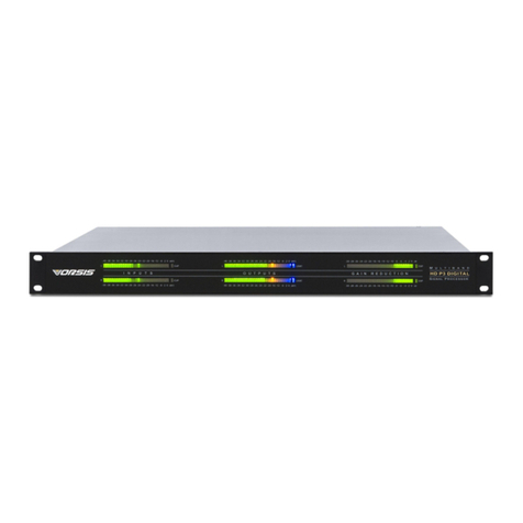
AP3 Digital Signal Processor
TECHNICAL MANUAL
600 Industrial Drive, New Bern, North Carolina, USA 28562
ORSIS
™

Vorsis
600 Industrial Drive
New Bern, North Carolina 28562
tel 252-638-7000 / fax 252-637-1285
AP3 Digital Signal Processor Technical Manual - 2nd EditionAP3 Digital Signal Processor Technical Manual - 2nd Edition
AP3 Digital Signal Processor Technical Manual - 2nd Edition
©2006 Vorsis
AP3/April 2005

page Contents – 1
AP3 / Jan 2006
CONTENTS
AP3 Technical Manual
Table of Contents
Chapter 1 – General Information
Introduction ...................................................................................1-2
Energizing ................................................................................................................. 1-2
I/O Connections.............................................................................1-3
Inputs ........................................................................................................................ 1-3
Outputs ..................................................................................................................... 1-4
Control Ports............................................................................................................. 1-5
Optional ANP-RJ Announcer Panel ...................................................................... 1-6
Remote ON, OFF, Cough ...................................................................................... 1-5
On and Off Tallies.................................................................................................. 1-6
General Purpose Interface ....................................................................................... 1-6
Ethernet Interface ..................................................................................................... 1-7
Typical Ethernet Cable .......................................................................................... 1-7
Typical Crossover Cable ....................................................................................... 1-7
Digital Audio Connections ........................................................................................ 1-8
Unbalanced Analog Connections ............................................................................. 1-8
Unbalanced Digital Connections (SPDIF) ................................................................ 1-8
XLR/RJ-45 Inputs Pinout Drawing............................................................................ 1-9
DB-25 Inputs/Outputs Pinout Drawing .................................................................... 1-10
XLR/RJ-45 Outputs Pinouts Drawing ...................................................................... 1-11
RJ-45/DB-9 Control/Ethernet/GPI Pinouts Drawing................................................ 1-12
Chapter 2 - Controls and Functions
Selecting a Signal Path.................................................................2-2
Basic Setup............................................................................................................... 2-3
SignalConditioning ......................................................................2-3
Input .......................................................................................................................... 2-3
Output ....................................................................................................................... 2-3
High-Pass Filter ........................................................................................................ 2-3
Notch......................................................................................................................... 2-3
Low-Pass Filter ......................................................................................................... 2-3
De-Esser ................................................................................................................... 2-3
Expander................................................................................................................... 2-4
Equalization ...................................................................................2-5
Parametric Equalizer ................................................................................................ 2-5
Dynamics .......................................................................................2-5
Multiband Compressor - “Production” ...................................................................... 2-5
Multiband Limiter - “Airchain”.................................................................................... 2-5
AGC .......................................................................................................................... 2-6
Limiter ....................................................................................................................... 2-6
Metering .........................................................................................2-6

page Contents – 2
AP3 / Jan 2006
CONTENTS
Main Control Group ......................................................................2-7
Presets ...........................................................................................2-7
Presets Button .......................................................................................................... 2-8
Take Button .............................................................................................................. 2-8
Save Button .............................................................................................................. 2-8
Modify ....................................................................................................................... 2-9
System Features and Settings.....................................................2-9
Password .................................................................................................................. 2-9
New Password ......................................................................................................... 2-10
Access ..................................................................................................................... 2-10
Inputs Follow Presets/Input Stay Same .................................................................. 2-10
Sample Rate ............................................................................................................ 2-10
IP Address ............................................................................................................... 2-11
Subnet/Gateway ...................................................................................................... 2-12
AP3 Front Panel Control Functions (Table 1-Table 3) ..............2-13
Chapter 3 - Vorsis AP3 GUI
Getting Started ..............................................................................3-3
Connecting the AP3 and the GUI.................................................3-3
Using the GUI ................................................................................3-4
Dynamic Displays Region......................................................................................... 3-5
Frequency-Domain Graph ................................................................................... 3-5
Bargraph Metering ............................................................................................... 3-6
Signal Path Selection .......................................................................................... 3-6
Control Area Region ................................................................................................. 3-7
Input ..................................................................................................................... 3-8
Symmetry......................................................................................................... 3-8
Phase............................................................................................................... 3-8
Filter ..................................................................................................................... 3-8
High-Pass Filter ............................................................................................... 3-8
Notch ............................................................................................................... 3-8
Low-Pass Filter................................................................................................ 3-8
Expander ............................................................................................................. 3-9
De-Esser............................................................................................................. 3-11
Emphasis and De-Emphasis .............................................................................. 3-12
Transmitter pre-emphasis .............................................................................. 3-13
Transmission path emulation ......................................................................... 3-14
M/S...................................................................................................................... 3-14
M/S microphones............................................................................................ 3-15
Mono Airchain Processing.............................................................................. 3-15
FM Airchain Processing ................................................................................. 3-15
Sum/Difference Processing for fun ................................................................ 3-15
Width............................................................................................................... 3-16
Mono Low Frequencies .................................................................................. 3-16
Output Limiter ..................................................................................................... 3-17
Output Limiter: In depth .................................................................................. 3-19
AP3 Features for AM Broadcast......................................................................... 3-20
Brick-wall Bandwidth ...................................................................................... 3-20
Emphasis ........................................................................................................ 3-20
Asymmetric Output Peak Limiter.................................................................... 3-21
Mono ............................................................................................................... 3-21

page Contents – 3
AP3 / Jan 2006
CONTENTS
Parametric Equalizer ....................................................................................... 3-21
Multiband Processing ...................................................................................... 3-22
Multi-Band AGC/Compressor - “Production”.............................................. 3-22
Transparent Compression .......................................................................... 3-25
Compressing for Effect............................................................................... 3-25
AGC ................................................................................................................. 3-27
Multiband Limiter - “Airchain” .......................................................................... 3-28
Loud! ................................................................................................................ 3-30
Creating a “sound”...................................................................................... 3-31
Deep Gain Reduction ................................................................................. 3-31
Setting Up the Output................................................................................. 3-32
System .................................................................................................................. 3-33
Side Bar Region.................................................................................................... 3-34
Take ................................................................................................................. 3-34
Save................................................................................................................. 3-34
Presets............................................................................................................. 3-35
Devices ............................................................................................................ 3-35
Q Save ............................................................................................................. 3-35
Compare .......................................................................................................... 3-35
Bypass ............................................................................................................. 3-35
Title Bar Region .................................................................................................... 3-36
Status............................................................................................................... 3-36
Devices ............................................................................................................ 3-36
Presets............................................................................................................. 3-37
Notes on “Online” and “Offline” working ............................................................... 3-38
Chapter 4 - Schematic and Load Sheet Drawings
Mic Audio Processor (AP3)
Schematic ............................................................................................................... 4-2
Load Sheet.............................................................................................................. 4-5
Processor Switch Card (PSW-1)
Load Sheet.............................................................................................................. 4-6
Appendices
Appendix 1
Using the AP3.............................................................................A-3
Five-MinuteProcessor............................................................................................A-3
About Listening .......................................................................................................A-4
Appendix 2
Parameters, Units and Ranges .................................................A-6
Appendix 3
Replacement Parts List ...........................................................A-11

G E N E R A L I NFORMATION
page 1 – 1
AP3 / Apr 2005
General Information
Chapter Contents
Introduction ................................................................................ 1-2
Energizing...............................................................................................................1-2
I/O Connections.......................................................................... 1-3
Inputs ......................................................................................................................1-3
Outputs ...................................................................................................................1-4
Control Ports...........................................................................................................1-5
Optional ANP-RJ Announcer Panel .................................................................... 1-6
Remote ON, OFF, Cough....................................................................................1-5
On and Off Tallies................................................................................................1-6
General Purpose Interface .....................................................................................1-6
Ethernet Interface ...................................................................................................1-7
Typical Ethernet Cable ........................................................................................ 1-7
Typical Crossover Cable .....................................................................................1-7
Digital Audio Connections ...................................................................................... 1-8
Unbalanced Analog Connections........................................................................... 1-8
Unbalanced Digital Connections (SPDIF).............................................................. 1-8
XLR/RJ-45 Inputs Pinout Drawing..........................................................................1-9
DB-25 Inputs/Outputs Pinout Drawing ................................................................. 1-10
XLR/RJ-45 Outputs Pinouts Drawing................................................................... 1-11
RJ-45/DB-9 Control/Ethernet/GPI Pinouts Drawing.............................................1-12

GENERAL INFORMATION
page 1 – 2
AP3 / Apr 2005
General Information
Introduction
The Vorsis™ AP3 Digital Signal Processor is a highly complex piece of audio
processing gear, the first product in a new line of a single-rack space audio
processors. This unit occupies one 19” wide rack space (height 1 3/4”), and is 16”
deep. The two-channel/stereo audio processor provides an array of analog/digital
inputs and outputs, four-band parametric EQ, three-band compressor, and tunable
filters along with overall AGC, limiting, and expansion. All settings can be stored
andreplayed as password-protectedpresets. The frontpanel display includesinput,
output, and gain reduction meters. Remote monitoring and operational control is
possible using Ethernet-enabled GUI software.
TheXLR,DB-25,DB-9andCAT5connectorslocatedontherearofchassisgive
you maximum installation versatility.
Energizing
AssumingtheVorsis™ AP3 Digital SignalProcessor is correctly rackmounted,
you may now energize it by connecting the factory supplied power cord to the
rackmount unit and then plugging it into the AC mains.
Note:To de-energizethe Vorsis™AP3, unplugits ACcord fromtheAC mains.
AP3 / Jan 2006

G E N E R A L I NFORMATION
page 1 – 3
AP3 / Apr 2005
I/O Connections
All audio input and output, control, Ethernet, and power supply connec-
tions are made via various connectors mounted on AP3’s the rear panel. Six
XLR connectors are provided for analog and digital audio input and output,
and all the audio connections also appear on the DB-25 connector. Two
RJ-45 connectors provide yet a third way to access the digital audio input
and output. Three additional RJ-45 connectors are provided for control and
Ethernet connections. The DB-9 connector provides 8 GPI inputs for the
most used presets. The pinout drawings on pages 1-9 through 1-12
summarize all wiring connections.
Inputs
Both AP3 processor signal paths can be fed from three different types
of inputs: microphone, analog line, and digital line.
When processing mic level (-50dBu nominal) inputs, the input is fed,
either from one of the two female XLR connectors (one each for the two
signal paths) or the appropriate pins on the DB-25 AUDIO I/O connector,
to the internal microphone preamplifiers. The mic preamps have digitally
controlled gain, up to a maximum of 70 dB, and display remarkably high
performance and accuracy. Phantom power (+32VDC) is available.
The same connections can be used for line level analog audio inputs
(nominal +4dBu balanced). When configured for analog line, the inputs
exhibit a bridging impedance and can handle signals up to +20dBu.
A third female XLR connector, along with a paralleled RJ-45 connector,
are available to handle digital line level sources; this AES digital input is
also available on the DB-25 connector. The AP3 will accommodate digital
inputs having sample rates of 44.1kHz or 48kHz. The sample rate of the
AP3 will automatically sync up to the applied input signal’s valid sample
rate, allowing the AP3 to be used in an existing digital system. AES sources
are by design stereo; if the AP3 is not set to be stereo the appropriate Left
or Right signal within the AES stream will be applied to the signal path.
MIC / Line In—XLR-F
Pin 1 XLR1 SH – MIC1 / LINE 1 IN SH
Pin 2 XLR1 HI – MIC1 / LINE 1 IN HI
Pin 3 XLR1 LO – MIC1 / LINE 1 IN LO
Pin 1 XLR2 SH – MIC2 / LINE 2 IN SH
Pin 2 XLR2 HI – MIC2 / LINE 2 IN HI
Pin 3 XLR2 LO – MIC2 / LINE 2 IN LO

G E N E R A L I NFORMATION
page 1 – 4
AP3 / Apr 2005
AES I
N
—XLR-F & RJ-45
RJ-45
Pin 1 – N/C
Pin 2 – N/C
Pin 3 – AES IN HI
Pin 4 – N/C
Pin 5 – N/C
Pin 6 – AES IN LO
Pin 7 – N/C
Pin 8 – N/C
XLR-F
Pin 1 XLR SH – AES IN SH
Pin 2 XLR HI – AES IN HI
Pin 3 XLR LO – AES IN LO
A
UDIO
I
NPUTS
—DB-25
Pin 25 – MIC 1 / LINE1 IN SH
Pin 24 – MIC 1 / LINE1 IN HI
Pin 12 – MIC 1 / LINE1 IN LO
Pin 11 – MIC 2 / LINE2 IN SH
Pin 10 – MIC 2 / LINE2 IN HI
Pin 23 – MIC 2 / LINE2 IN LO
Pin 16 – AES IN SH
Pin 15 – AES IN HI
Pin 3 – AES IN LO
Outputs
The AP3’s two output signals are available as individual line level analog (+4dBu,
balanced) on the two male XLR ANALOG OUT connectors, and in digital AES formatted
on a male XLR connector, paralleled by an RJ-45 connector for CAT5 connection. These
analog and digital outputs are available also on the DB-25 connector.
A
NALOG
O
UT
—XLR-M
Pin 1 XLR1 SH – LINE 1 OUT SH
Pin 2 XLR1 HI – LINE 1 OUT HI
Pin 3 XLR1 LO – LINE 1 OUT LO
Pin 1 XLR2 SH – LINE 2 OUT SH
Pin 2 XLR2 HI – LINE 2 OUT HI
Pin 3 XLR2 LO – LINE 2 OUT LO
AES O
UT
—XLR-M & RJ-45
RJ-45
Pin 1 – N/C
Pin 2 – N/C
Pin 3 – AES OUT HI
Pin 4 – N/C
Pin 5 – N/C
Pin 6 – AES OUT LO
Pin 7 – N/C
Pin 8 – N/C

G E N E R A L I NFORMATION
page 1 – 5
AP3 / Apr 2005
XLR-M
Pin 1 XLR SH – AES OUT SH
Pin 2 XLR HI – AES OUT HI
Pin 3 XLR LO – AES OUT LO
A
UDIO
O
UTPUTS
—DB-25
Pin 8 – LINE 1 OUT SH
Pin 7 – LINE 1 OUT HI
Pin 20 – LINE 1 OUT LO
Pin 19 – LINE 2 OUT SH
Pin 18 – LINE 2 OUT HI
Pin 6 – LINE 2 OUT LO
Pin 2 – AES OUT SH
Pin 1 – AES OUT HI
Pin 14 – AES OUT LO
Control Ports
There are two RJ-45 connectors (one for each signal path) available for the
connections of a talent microphone control panel. Functions include remote on and
off, cough, and tally.
C
ONTROL
—RJ-45
Pin 1 – DIGITAL GROUND
Pin 2 – COUGH
Pin 3 – N/C
Pin 4 – OFF TALLY
Pin 5 – ON TALLY
Pin 6 – REMOTE OFF
Pin 7 – REMOTE ON
Pin 8 – +5V DIGITAL
Optional ANP-RJ Announcer Panel
The optional ANP-RJ panel connects to the AP3 using a standard straight
CAT5 Ethernet cable. This panel has “ON”, “OFF”, and “COUGH” switches
for remote control of the microphone inputs. (Note that the “TB” button is not
usable for the AP3). The “ON” and “OFF” buttons are LED illuminated. These
panels can be mounted directly into a furniture surface or a turret.
To Turn the Microphone ON & OFF from a Remote Location
NOTE: The remote mic controls are meant to be used when the AP3 is
processing two separate mono signals, typically microphones (see “Selecting a
Signal Path” on pages 2-7 to 2-8). If the AP3 is in “stereo” mode there will be some
non-intuitive interaction between the two sets of remote mic controls.
REMOTE ON — Activates the mic’s channel ON switch. Provide a momen-
tary closure between Remote On (Pin 7) and Digital Ground (Pin 1). This will latch
the mic ON. (User-supplied momentary contact switch required.)

G E N E R A L I NFORMATION
page 1 – 6
AP3 / Apr 2005
REMOTE OFF — Activates the mic’s channel OFF switch. Pro-
vide a momentary closure between Remote Off (Pin 6) and Digital
Ground (Pin 1). This will latch the mic OFF. (User-supplied momen-
tary contact switch required.)
COUGH — Temporarily Mutes the microphone. Provide a closure
between Cough (Pin 2) and Digital Ground (Pin 1). This will turn the
mic OFF. Note this is a non-latching mode; the mic will turn ON again
as soon as the closure stops. (User-supplied momentary contact switch
required.)
On and Off Tallies
ON TALLY — Lets the mic’s channel ON switch control an on-air
light or other “microphone on” indicator at a remote location. This
control function provides a continuous closure (open collector) be-
tween On Tally (Pin 5) and Digital Ground (Pin 1) whenever the
module is ON.
OFF TALLY — Lets the mic’s channel OFF switch control an on-
air light or other “microphone off” indicator at a remote location. This
control function provides a continuous closure (open collector) be-
tween Off Tally (Pin 4) and Digital Ground (Pin 1) whenever the
module is ON.
The On and Off Tallies can be used to control externally powered
tally lights that require a continuous closure to function, or external
tally lights (i.e., LED) can be powered from the tally output by
connecting the external LED to +5V Digital (Pin 8)* and the On Tally
port (Pin 5) or Off Tally port (Pin 4). In any case, current should not
exceed 30 milliamps.
General Purpose Interface
This general purpose interface is used to remotely trigger (recall)
Presets 1-8. For example, a 5VDC signal applied between Pin 1 (GPI
Com) and Pin 6 (GPI 1 In), will take the AP3 preset stored in location
PRE #001. The + (plus) side of the 5V signal is applied to the active
selector pin (Pin 6 in the example) and the - (minus) side of the 5V
signal is applied to GPI Com, Pin 1.
GPI—DB-9
Pin 1 – GPI COM
Pin 6 – GPI 1 IN
Pin 2 – GPI 2 IN
Pin 7 – GPI 3 IN
Pin 3 – GPI 4 IN
Pin 8 – GPI 5 IN
Pin 4 – GPI 6 IN
Pin 9 – GPI 7 IN
Pin 5 – GPI 8 IN
*We recommend a se-
ries resistor between the
LED and +5V digital
when you are powering
the external tally from the
AP3; a value of 220Ω(1/
4W 5%) is suggested.

G E N E R A L I NFORMATION
page 1 – 7
AP3 / Apr 2005
Ethernet Interface
Networked systems are connected to the AP3 via straight (pin to pin) CAT5
cable. For typical CAT5 cable pinouts see below. These connections are for
communicating with the configuration computer, via a network. If you are
connecting directly between the computer and the AP3 with no network in
between, use a crossover cable.
E
THERNET
—RJ-45
Pin 1 – TXD +
Pin 2 – TXD -
Pin 3 – RXD +
Pin 4 – N/C
Pin 5 – N/C
Pin 6 – RXD -
Pin 7 – N/C
Pin 8 – N/C
T
YPICAL
E
THERNET
C
ABLE
T
YPICAL
C
ROSSOVER
C
ABLE
1
2
3
4
TXD +
TXD -
RXD +
RXD -
PIN
1
2
3
4
PIN
RJ-45
Plug RJ-45
Plug
White/Orange
5
6
7
8
N/C
N/C
5
6
7
8
Orange
White/Green
Blue
White/Blue
Green
White/Brown
Brown
N/C
N/C
White/Orange
Orange
White/Green
Blue
White/Blue
Green
White/Brown
Brown
1
2
3
4
TXD +
TXD -
RXD +
RXD -
PIN
1
2
3
4
PIN
RJ-45
Plug RJ-45
Plug
White/Orange
5
6
7
8
N/C
N/C
5
6
7
8
Orange
White/Green
Blue
White/Blue
Green
White/Brown
Brown
White/Green
Green
White/Orange
Blue
White/Blue
Orange
White/Brown
Brown
N/C
N/C
RXD +
RXD -
TXD +
TXD -
N/C
N/C
N/C
N/C

G E N E R A L I NFORMATION
page 1 – 8
AP3 / Apr 2005
Digital Audio Connections
CABLE - All AES/EBU input and output digital audio connections are balanced
and should be made using a high quality digital audio cable. Be sure to select a digital
audio cable with an integral drain wire of the same wire gauge (AWG) as the twisted
pair as this facilitates an easier consistent termination process. Typical AES/EBU
digital audio cable has a very low characteristic capacitance per ft (pF/ft), and a
nominal impedance of 110Ω. High quality digital audio cable offers better signal
transmission performance versus typical analog audio cable, especially over long
cable runs. Check the cable manufacturer’s data sheet to be sure the cable you plan
to use will work in your application.
CONNECTORS - The AES/EBU connections are made with the supplied DB-25
male mating connector, or with XLR or RJ-45 connectors. The DB-25 crimp style
connector will accept wire gauge 22 - 28AWG. Please refer to the RJ-45 and XLR
mating connector manufacturer's recommendations for termination instructions.
Unbalanced Analog Connections
ANALOG INPUTS — Wire to the processor input end with typical shielded, two
conductor cable (like Belden 9451), just as if you were connecting a balanced source.
At the unbalanced source machine’s output, connect the + output to the HI input wire
and connect the source machine GND wire to LO. Connect the shield at the AP3 end
only.
Note: Unbalanced analog sources typically have -10dBv (316mV RMS) signal levels
and will not match the processor nominal operating level of +4dBu (1.23V RMS). We
highly recommended that you first externally balance any unbalanced sources you
plan on connecting to the Vorsis™ AP3. Many third party “match boxes” are
commercially available for this.
ANALOG OUTPUTS — The AP3 analog outputs use a balanced output circuit
which behaves exactly like the secondary of a high-quality transformer, with no
center tap—this output is both balanced and floating. For unbalanced operation,
either the HI or LO side of the analog output must be strapped to ground of the
unbalanced input, with the output taken from the other side. (Normally you would
strap LO to ground, and use HI to feed your unbalanced equipment input.) Leave the
SH floating at one end.
Unbalanced Digital Connections (SPDIF)
SPDIF INPUTS — The SPDIF (Sony/Phillips Digital Interface) or “consumer”
digital audio interface is a two wire unbalanced signal typically on a single RCA style
connector. Note that the SPDIF signal level of approximately 500mV and 75 ohm
impedance does not correctly match the processor AES inputs. We highly recom-
mend using a “balun” or format converter when interfacing “consumer” grade source
devices to the processor.
In cases where a consumer grade device must be interfaced and the appropriate
matching device is not available, try wiring the SPDIF center conductor (HOT) to the
HI input pin and SPDIF shell (ground) to the LO input. Connect SH at the processor
end only.
SPDIF OUTPUTS — The Vorsis™ AP3 digital outputs are fixed, professional,
AES-3 formatted outputs. SPDIF consumer format is not supported. Use an external
format converter to connect the digital outputs to consumer gear.

G E N E R A L I NFORMATION
page 1 – 9
AP3 / Apr 2005
Mic/Line In - XLR-F
2
1
3
PIN 1 XLR SH - MIC 1 / LINE 1 IN SH
PIN 2 XLR HI - MIC 1 / LINE 1 IN HI
PIN 3 XLR LO - MIC 1 / LINE 1 IN LO
XLR1-F
2
1
3
PIN 1 XLR SH - MIC 2 / LINE 2 IN SH
PIN 2 XLR HI - MIC 2 / LINE 2 IN HI
PIN 3 XLR LO - MIC 2 / LINE 2 IN LO
XLR2-F
AES In - XLR-F & RJ-45
2
1
3PIN 1 XLR SH - AES IN SH
PIN 2 XLR HI - AES IN HI
PIN 3 XLR LO - AES IN LO
XLR-F
1
2
3
4
5
6
7
8
RJ-45 AES IN HI
AES IN LO
N/C
N/C
N/C
N/C
N/C
N/C

G E N E R A L I NFORMATION
page 1 – 10
AP3 / Apr 2005
Audio Input / Output
MIC 1 / LINE 1 IN HI
MIC 2 / LINE 2 IN LO
N/C
LINE 1 OUT LO
LINE 2 OUT SH
LINE 2 OUT HI
N/C
AES IN SH
AES IN HI
AES OUT LO
AUDIO GROUND
MIC 1 / LINE 1 IN LO
MIC 2 / LINE 2 IN SH
MIC 2 / LINE 2 IN HI
N/C
LINE 1 OUT SH
LINE 1 OUT HI
LINE 2 OUT LO
N/C
N/C
AES IN LO
AES OUT SH
AES OUT HI
5
4
3
2
1
17
16
15
14
8
7
6
20
19
18
10
9
23
22
21
13
12
11
25
24
MIC 1 / LINE 1 IN SH
N/C
DB-25

G E N E R A L I NFORMATION
page 1 – 11
AP3 / Apr 2005
1
2
3
Analog Out - XLR-M
PIN 1 XLR SH - LINE 1 OUT SH
PIN 2 XLR HI - LINE 1 OUT HI
PIN 3 XLR LO - LINE 1 OUT LO
XLR1-M
PIN 1 XLR SH - LINE 2 OUT SH
PIN 2 XLR HI - LINE 2 OUT HI
PIN 3 XLR LO - LINE 2 OUT LO
XLR2-M
AES Out - XLR-M & RJ-45
PIN 1 XLR SH - AES OUT SH
PIN 2 XLR HI - AES OUT HI
PIN 3 XLR LO - AES OUT LO
XLR-M
1
2
3
4
5
6
7
8
RJ-45 AES OUT HI
AES OUT LO
1
2
3
1
2
3
N/C
N/C
N/C
N/C
N/C
N/C

G E N E R A L I NFORMATION
page 1 – 12
AP3 / Apr 2005
1
2
3
4
5
6
7
8
DIGITAL GROUND
COUGH
N/C
REMOTE OFF
MIC 1
RJ-45 #1
OFF TALLY
ON TALLY
REMOTE ON
+5V DIGITAL
Control - RJ-45
1
2
3
4
5
6
7
8
DIGITAL GROUND
COUGH
N/C
REMOTE OFF
MIC 2
RJ-45 #2 OFF TALLY
ON TALLY
REMOTE ON
+5V DIGITAL
1
2
3
4
5
6
7
8
TXD +
TXD -
RXD +
RXD -
ETH
RJ-45 N/C
N/C
N/C
N/C
Ethernet - RJ-45
GPI 7 IN
GPI 5 IN
GPI 1 IN
GPI 8 IN
GPI 6 IN
GPI 4 IN
GPI 2 IN
GPI COM
GPI 3 IN
GPI
GPI
DB-9

CONTROLS AND FUNCTIONS
page 2 – 1
AP3 / Jan 2006
AP3 Controls and Functions
Chapter Contents
Selecting a Signal Path.................................................................2-2
Basic Setup............................................................................................................... 2-3
SignalConditioning ......................................................................2-3
Input .......................................................................................................................... 2-3
Output ....................................................................................................................... 2-3
High-Pass Filter ........................................................................................................ 2-3
Notch......................................................................................................................... 2-3
Low-Pass Filter ......................................................................................................... 2-3
De-Esser ................................................................................................................... 2-3
Expander................................................................................................................... 2-4
Equalization ...................................................................................2-5
Parametric Equalizer ................................................................................................ 2-5
Dynamics .......................................................................................2-5
Multiband Compressor - “Production” ...................................................................... 2-5
Multiband Limiter - “Airchain”.................................................................................... 2-5
AGC .......................................................................................................................... 2-6
Limiter ....................................................................................................................... 2-6
Metering .........................................................................................2-6
Main Control Group ......................................................................2-7
Presets ...........................................................................................2-7
Presets Button .......................................................................................................... 2-8
Take Button .............................................................................................................. 2-8
Save Button .............................................................................................................. 2-8
Modify ....................................................................................................................... 2-9
System Features and Settings.....................................................2-9
Password .................................................................................................................. 2-9
New Password ......................................................................................................... 2-10
Access ..................................................................................................................... 2-10
Inputs Follow Presets/Input Stay Same .................................................................. 2-10
Sample Rate ............................................................................................................ 2-10
IP Address ............................................................................................................... 2-11
Subnet/Gateway ...................................................................................................... 2-12
AP3 Front Panel Control Functions (Table 1-Table 3) ..............2-13

CONTROLS AND FUNCTIONS
page 2 – 2
AP3 / Jan 2006
AP3 Controls and Functions
Asinternally complexas isthe AP3,and assmall asisthe front-panel,
it is obviously not possible to provide a control-per-function, as desirable
as that may be. However, considerable effort has gone into making the
front-panel controls logical and usable.
Awidevarietyofbothfrequency-responseshapinganddynamicstools
(on the right-hand side of the front panel) are available for selection and
adjustmentineachAP3signalpathviatheswitchesontheright-handside
ofthefront panel.Despitetheconsiderableoverlap infunctionality,these
will be grouped into Signal Conditioning, Equalization, and Dynamics.
Thisalsoapproximatelyrepresents(exceptions willbenoted)theorderin
which these tools are applied to the signal paths.
Most of the functions described in this chapter are covered in greater
detail in Chapter 3.
Selecting a Signal Path
The front panel Channel 1 and 2 buttons determine which of the two
AP3signalpathsisbeingoperatedupon-theappropriatepath’sbuttonwill
belit;pressingtheotherbuttonwillcauseittobelitinstead,andcommand
anddisplay now acton that path.The AP3 canbe made “stereo”(i.e. both
paths being controlled together) by simultaneously holding down both
Channel1and2buttonsfortwoseconds;bothbuttonswilllightsignifying
both are under command, and henceforth both paths track together.
BothChannel1andChannel2willadoptthesettingsofthepathwhich
was last selected for control at the time of making the AP3 stereo.
An important exception to this adoption of a single set of parameters
for stereo is Input Gain settings; if there is a difference between the
Channel 1 and Channel 2 paths’ input gains (such as could easily occur
withtwomicrophones,evenasastereopair)thisoffsetwillbemaintained
betweenthetwoinputgainsasthenow“stereo”inputgainisadjusted.This
offsetwillbeignoredatgainextremes(i.e.bothpathswillultimatelyreach
maxormingain)buttheoffsetwillberetainedandreappliedwhenthegain
returns to saner values.
Additionally, the dynamics signal processing will become married,
such that independent Channel 1 and Channel 2 gain variation and
resulting stereo image shifting cannot occur.
Revertingtotwoindependentpathsagainisachievedbyholdingdown
either the Channel 1 or 2 button for two seconds. Both path’s settings
adopt,until subsequently altered,the settingsattained duringthe“stereo”
usage.

CONTROLS AND FUNCTIONS
page 2 – 3
AP3 / Jan 2006
Basic Setup
Beforeyoucanstarttweakingyoursignalfromthefrontpanelthereare
afewbasicfunctionsyoumustaccessandconfigureforyoursignalchain;
selecting a source, setting mode, and input/output level control.
Source - Press the INPUT switch to select the following source type -
Mic, Line, or AES (digital). Also set M/S - L/R (sum & diff or stereo) to
L/R for “normal operation”.
OutputMODE- ForStereooperationsetM/S-L/RtoL/R.ForMONO
operation set M/S - L/R to M/S and use the L channel output.
GAIN-PresstheGAINswitchtoaccesstheinput/outputgaincontrols.
AESClockErrorMessages-willflashobnoxiouslyiftheSampleRate
is set to AUTO and no AES input is connected or if your AES source and
theAP3don’tagreeonasamplerate.SeetheAESErrorMessagessection
(page 2-11) to decipher these.
SignalConditioning
Generallythesefunctionsremoveundesiredsignalsandartifactsfrom
the source material.
High-Pass Filter
Afastrolloff-ratehigh-passfilter,adjustablebetween20Hzand1kHz,
serves to aid removal of low-frequency signals and noises, such as air-
conditioningrumble,tablethumps,orinthecaseofaTELCOsource,line-
borne noises below the conducted frequency range (typically 300Hz).
Notch
The notch has been optimized in terms of width and depth to do the
most damage to an undesired signal (such as supply-line hum, a TV/
computer line-timebase while, or an annoying instrument “ring”) whine
doing the least damage to the desired audio; it is at once broad enough to
be reasonably easy to use in “finding” the offending signal, yet narrow
enough not to impart excessive coloration to adjacent frequencies. It is
tunable over the entire audio range of 20Hz – 20kHz.
Low-Pass Filter
Afastrolloff-ratelow-passfilter,adjustablebetween20kHzand1kHz,
aidsintheremovalofdistractinghigh-frequencynoises,ortodeliberately
restrict the program material’s bandwidth.
De-Esser
Thede-esserisadynamicfilterwhichreducesthesignalenergywithin
a chosen band of frequencies when it has been sensed to exceed a desired
level.Thisisavaluabletoolinreducingprominentsibilance(pronounced
“SSS” noises) on some voices, particularly if poorly recorded or subject
to poor or overly close microphone technique. It is also often used to help
control the “honky” effect on phone lines.
TIP: Some function set-
tings are “paged”. See
page 2-7 for a descrip-
tion of the paging con-
trols, and see the chart
in page 2-13 for menu
page location of various
functions.
Table of contents
Other Vorsis Signal Processor manuals