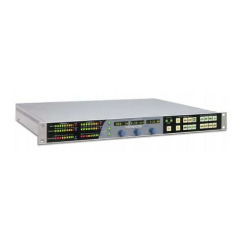
Vorsis HD P3 User manual

TECHNICAL MANUAL
600 Industrial Drive, New Bern, North Carolina, USA 28562
M
ULTIBAND
S
IGNAL
P
ROCESSOR
HD P3 DIGITAL
ORSIS
®

Vorsis
600 Industrial Drive
New Bern, North Carolina 28562
tel 252-638-7000 / fax 252-637-1285
HD P3 Digital Multiband Signal Processor Technical ManualHD P3 Digital Multiband Signal Processor Technical Manual
HD P3 Digital Multiband Signal Processor Technical Manual
©2006 Vorsis
HD P3/Aug 2006

AA
AA
ATTENTIONTTENTION
TTENTIONTTENTION
TTENTION
RR
RR
READEAD
EADEAD
EAD MM
MM
M
EE
EE
E!!
!!
!
HD P3 / Aug 2006
Attention!
FF
FF
Federal Communications Commission (FCC) Complianceederal Communications Commission (FCC) Compliance
ederal Communications Commission (FCC) Complianceederal Communications Commission (FCC) Compliance
ederal Communications Commission (FCC) Compliance
Notice:Notice:
Notice:Notice:
Notice:
Radio FRadio F
Radio FRadio F
Radio Frequency Noticerequency Notice
requency Noticerequency Notice
requency Notice
NOTE:NOTE:
NOTE:NOTE:
NOTE: This equipment has been tested and found to comply with the
limits for a Class A digital device, pursuant to Part 15 of the FCC rules. These
limits are designed to provide reasonable protection against harmful
interference when the equipment is operated in a commercial environment.
This equipment generates, uses, and can radiate radio frequency energy
and, if not installed and used in accordance with the instruction manual,
may cause harmful interference to radio communications. Operation of this
equipment in a residential area is likely to cause harmful interference in
which case the user will be required to correct the interference at his own
expense.
!
This is a Class A product. In a domestic environment, thisThis is a Class A product. In a domestic environment, this
This is a Class A product. In a domestic environment, this
product may cause radio interference, in which case, theproduct may cause radio interference, in which case, the
product may cause radio interference, in which case, the
user may be required to take appropriate measures.user may be required to take appropriate measures.
user may be required to take appropriate measures.
This equipment must be installed and wired properly in order to assure
compliance with FCC regulations.
Caution!Caution!
Caution!Caution!
Caution!
Any modifications not expressly approved in writing byAny modifications not expressly approved in writing by
Any modifications not expressly approved in writing by
Wheatstone could void the user's authority to operate this equipment.Wheatstone could void the user's authority to operate this equipment.
Wheatstone could void the user's authority to operate this equipment.

page Contents – 1
HD P3 / Aug 2006
CONTENTS
HD P3 Technical Manual
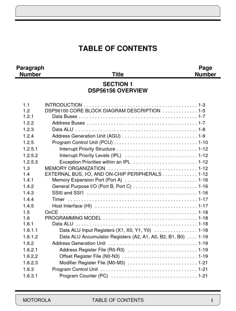
Table of Contents
Chapter 1 – General Information
Introduction ...................................................................................1-2
Energizing ................................................................................................................. 1-2
I/O Connections.............................................................................1-3
Inputs ........................................................................................................................ 1-3
Outputs ..................................................................................................................... 1-4
General Purpose Interface ....................................................................................... 1-5
Ethernet Interface ..................................................................................................... 1-5
Typical Ethernet Cable .......................................................................................... 1-5
Typical Crossover Cable ....................................................................................... 1-6
Digital Audio Connections ........................................................................................ 1-6
Unbalanced Analog Connections ............................................................................. 1-6
Unbalanced Digital Connections (SPDIF) ................................................................ 1-7
XLR Inputs/Outputs Pinout Drawing......................................................................... 1-8
DB-25 Inputs/Outputs,RJ-45 Ethernet, & DB-9 GPI Pinout Drawing....................... 1-9
Chapter 2 - Vorsis HD P3 GUI
Getting Started ..............................................................................2-3
Connecting the HD P3 and the GUI .............................................2-3
IP Address Configuration.............................................................2-4
Creating a New Device ............................................................................................. 2-4
Changing the HD P3 IP Address .............................................................................. 2-5
Troubleshooting IP Addressing Problems ................................................................ 2-5
Windows Network Status Icons ................................................................................ 2-6
A Word About Networks...............................................................2-6
Using the GUI ................................................................................2-7
Dynamic Displays Region......................................................................................... 2-8
Frequency-Domain Graph ................................................................................... 2-8
Bargraph Metering ............................................................................................... 2-9
Signal Path Selection .......................................................................................... 2-9
Control Area Region ................................................................................................ 2-10
Input .................................................................................................................... 2-11
Signal Path Routing........................................................................................ 2-12
Symmetry........................................................................................................ 2-12
Phase.............................................................................................................. 2-12

page Contents – 2
HD P3 / Aug 2006
CONTENTS
Filter .................................................................................................................... 2-13
High-Pass Filter .............................................................................................. 2-13
Notch .............................................................................................................. 2-13
Low-Pass Filter............................................................................................... 2-13
Expander ............................................................................................................ 2-13
De-Esser............................................................................................................. 2-15
Emphasis and De-Emphasis .............................................................................. 2-16
Transmitter pre-emphasis .............................................................................. 2-17
Transmission path emulation ......................................................................... 2-18
M/S...................................................................................................................... 2-18
M/S microphones............................................................................................ 2-19
Mono Airchain Processing.............................................................................. 2-19
FM Airchain Processing ................................................................................. 2-19
Sum/Difference Processing for fun ................................................................ 2-19
Width............................................................................................................... 2-20
Mono Low Frequencies .................................................................................. 2-20
Output Limiter ..................................................................................................... 2-21
Output Limiter: In depth.................................................................................. 2-23
AES Output 2 Delay ....................................................................................... 2-24
Entering Delay Value...................................................................................... 2-24
HD P3 Features for AM Broadcast..................................................................... 2-25
Brick-wall Bandwidth ...................................................................................... 2-25
Emphasis ........................................................................................................ 2-25
Asymmetric Output Peak Limiter.................................................................... 2-26
Mono ............................................................................................................... 2-26
Parametric Equalizer .......................................................................................... 2-26
Multiband Processing ......................................................................................... 2-27
Multi-Band AGC/Compressor - “Production”................................................. 2-27
Transparent Compression ............................................................................. 2-30
Compressing for Effect.................................................................................. 2-30
AGC .................................................................................................................... 2-31
Multiband Limiter - “Airchain” ............................................................................. 2-33
Loud! ................................................................................................................... 2-35
Creating a “sound”......................................................................................... 2-36
Deep Gain Reduction .................................................................................... 2-36
Setting Up the Output .................................................................................... 2-37
System ..................................................................................................................... 2-38
Side Bar Region....................................................................................................... 2-39
Take .................................................................................................................... 2-39
Save.................................................................................................................... 2-39
Presets................................................................................................................ 2-40
Devices ............................................................................................................... 2-40
Q Save ................................................................................................................ 2-40
Compare ............................................................................................................. 2-40
Bypass ................................................................................................................ 2-40
Title Bar Region ....................................................................................................... 2-41
Accessing Menu Options.................................................................................... 2-41
Status.................................................................................................................. 2-41
Devices ............................................................................................................... 2-42
Presets................................................................................................................ 2-42
Notes on “Online” and “Offline” Working ................................................................. 2-43
Hardware Menu Items ............................................................................................. 2-44
Software Updates .................................................................................................... 2-44

page Contents – 3
HD P3 / Aug 2006
CONTENTS
Chapter 3 - Schematic and Load Sheet Drawings
HD P3 Processor Main Card
Schematic ............................................................................................................... 3-2
Load Sheet.............................................................................................................. 3-5
HD P3 Processor VU Card
Schematic ............................................................................................................... 3-6
Load Sheet.............................................................................................................. 3-7
Appendices
Appendix 1
Parameters, Units and Ranges .................................................A-3
Appendix 2
Replacement Parts List .............................................................A-8

GENERAL INFORMATION
page 1 – 1
HD P3 / Aug 2006
General Information
Chapter Contents
Introduction ................................................................................ 1-2
Energizing ............................................................................................................... 1-2
I/O Connections.......................................................................... 1-3
Inputs ...................................................................................................................... 1-3
Outputs ................................................................................................................... 1-4
General Purpose Interface ..................................................................................... 1-5
Ethernet Interface ................................................................................................... 1-5
Typical Ethernet Cable ........................................................................................ 1-5
Typical Crossover Cable ..................................................................................... 1-6
Digital Audio Connections ...................................................................................... 1-6
Unbalanced Analog Connections ........................................................................... 1-6
Unbalanced Digital Connections (SPDIF) .............................................................. 1-7
XLR Inputs/Outputs Pinout Drawing....................................................................... 1-8
DB-25 Inputs/Outputs,RJ-45 Ethernet, & DB-9 GPI Pinout Drawing..................... 1-9

GENERAL INFORMATION
page 1 – 2
HD P3 / Aug 2006
General Information
Introduction
The Vorsis HD P3 Digital Multiband Signal Processor unit occupies one 19”
wide rack space (height 1 3/4”), and is 17.346” deep. The two-channel/stereo audio
processorprovidesanarrayofanalog/digitalinputsandoutputs,four-bandparamet-
ricEQ,three-bandcompressor,andtunablefilters,alongwithoverallAGC,limiting,
and expansion. All settings can be stored and replayed as password-protected
presets. The front panel display includes input, output, and gain reduction meters.
RemotemonitoringandoperationalcontrolispossibleusingEthernet-enabledGUI
software.
TheXLR,DB-25,DB-9andCAT5connectorslocatedontherearofchassisgive
you maximum installation versatility.
Energizing
Assuming the Vorsis HD P3 Digital Multiband Signal Processor is correctly
rackmounted, you may now energize it by connecting the factory supplied power
cord to the rackmount unit and then plugging it into the AC mains.
Note:Tode-energizetheVorsis HD P3,unplug its ACcord from theAC mains.

GENERAL INFORMATION
page 1 – 3
HD P3 / Aug 2006
I/O Connections
All audio input and output, control, Ethernet, and power supply
connections are made via various connectors mounted on HD P3’s rear
panel. Seven XLR connectors are provided for analog and digital audio
input and output, and all the audio connections also appear on the DB-25
connector.AnRJ-45connectorisprovidedforEthernet connections. The
DB-9 connector provides 8 GPI inputs for the most used presets. The
pinout drawings on pages 1-8 and 1-9 summarize all wiring connections.
Inputs
BothHDP3processorsignalpathscanbefedfromtwodifferenttypes
of inputs: analog line level and AES-3 digital.
Two female XLR connectors, or the appropriate pins on the DB-25
AUDIO I/O connector, are available for line level analog audio input
(nominal +4dBu balanced) connections. The analog line inputs exhibit a
bridging impedance and can handle signals up to +20dBu.
A third female XLR connector is available to handle digital line level
sources;thisAES-3digitalinputisalsoavailableontheDB-25connector.
The HD P3 will accommodate digital inputs having sample rates of
44.1kHz or 48kHz. The internal sample rate of the HD P3 will automati-
cally sync up to the applied input signal’s valid sample rate, allowing the
HDP3tobeused in an existingdigitalsystem.AESsources are by design
stereo; if the HD P3 is not set to be stereo the appropriate Left or Right
signal within the AES stream will be applied to the signal path.
Line In—XLR-F
Pin 1 XLR1 SH – LINE 1 IN SH
Pin 2 XLR1 HI – LINE 1 IN HI
Pin 3 XLR1 LO – LINE 1 IN LO
Pin 1 XLR2 SH – LINE 2 IN SH
Pin 2 XLR2 HI – LINE 2 IN HI
Pin 3 XLR2 LO – LINE 2 IN LO
AES I
N
—XLR-F
Pin 1 XLR SH – AES IN SH
Pin 2 XLR HI – AES IN HI
Pin 3 XLR LO – AES IN LO

GENERAL INFORMATION
page 1 – 4
HD P3 / Aug 2006
A
UDIO
I
NPUTS
—DB-25
Pin 25 – LINE1 IN SH
Pin 24 – LINE1 IN HI
Pin 12 – LINE1 IN LO
Pin 11 – LINE2 IN SH
Pin 10 – LINE2 IN HI
Pin 23 – LINE2 IN LO
Pin 5 – AES IN SH
Pin 4 – AES IN HI
Pin 17 – AES IN LO
Outputs
The HD P3’s two output signals are available as individual line level analog (+4dBu,
balanced) on the two male XLR ANALOG OUT connectors, and in digital AES formatted
on the two male XLR AES OUT connectors. These analog and digital outputs are available
also on the DB-25 connector.
A
NALOG
O
UT
—XLR-M
Pin 1 XLR1 SH – LINE 1 OUT SH
Pin 2 XLR1 HI – LINE 1 OUT HI
Pin 3 XLR1 LO – LINE 1 OUT LO
Pin 1 XLR2 SH – LINE 2 OUT SH
Pin 2 XLR2 HI – LINE 2 OUT HI
Pin 3 XLR2 LO – LINE 2 OUT LO
AES O
UT
—XLR-M
Pin 1 XLR1 SH – AES 1 OUT SH
Pin 2 XLR1 HI – AES 1 OUT HI
Pin 3 XLR1 LO – AES 1 OUT LO
Pin 1 XLR2 SH – AES 2 OUT SH
Pin 2 XLR2 HI – AES 2 OUT HI
Pin 3 XLR2 LO – AES 2 OUT LO
A
UDIO
O
UTPUTS
—DB-25
Pin 8 – LINE 1 OUT SH
Pin 7 – LINE 1 OUT HI
Pin 20 – LINE 1 OUT LO
Pin 19 – LINE 2 OUT SH
Pin 18 – LINE 2 OUT HI
Pin 6 – LINE 2 OUT LO
Pin 16 – AES 1 OUT SH
Pin 15 – AES 1 OUT HI
Pin 3 – AES 1 OUT LO
Pin 2 – AES 2 OUT SH
Pin 1 – AES 2 OUT HI
Pin 14 – AES 2 OUT LO

GENERAL INFORMATION
page 1 – 5
HD P3 / Aug 2006
General Purpose Interface
Thisgeneralpurposeinterfaceisusedtoremotelytrigger(recall)Presets1-8.For
example,a5VDCsignalapplied between Pin 1(GPICom)andPin 6 (GPI 1In),will
takethe HD P3presetstoredinlocationPRE#001.The+(plus)sideof the5Vsignal
is applied to the active selector pin (Pin 6 in the example) and the - (minus) side of
the 5V signal is applied to GPI Com, Pin 1.
GPI—DB-9
Pin 1 – GPI COM
Pin 6 – GPI 1 IN
Pin 2 – GPI 2 IN
Pin 7 – GPI 3 IN
Pin 3 – GPI 4 IN
Pin 8 – GPI 5 IN
Pin 4 – GPI 6 IN
Pin 9 – GPI 7 IN
Pin 5 – GPI 8 IN
Ethernet Interface (100Mbps)
ConnectyourHDP3toyourlocalEthernetnetworkusinga“straight”(pintopin)
CAT5 cable. The default IP address and subnet is 192.168.1.191/255.255.255.0.
PleaserefertotheHDP3softwarefordetailsonchangingthedefaultIPaddress.Use
a crossover cable for peer-to-peer connection (i.e. direct connection between a
computer and the HD P3). For typical CAT5 cable pinouts see below.
E
THERNET
—RJ-45
Pin 1 – TXD +
Pin 2 – TXD -
Pin 3 – RXD +
Pin 4 – N/C
Pin 5 – N/C
Pin 6 – RXD -
Pin 7 – N/C
Pin 8 – N/C
T
YPICAL
E
THERNET
C
ABLE
1
2
3
4
TXD +
TXD -
RXD +
RXD -
PIN
1
2
3
4
PIN
RJ-45
Plug RJ-45
Plug
White/Orange
5
6
7
8
N
/C
N
/C
5
6
7
8
Orange
White/Green
Blue
White/Blue
Green
White/Brown
Brown
N
/C
N
/C
White/Orange
Orange
White/Green
Blue
White/Blue
Green
White/Brown
Brown

G E N E R A L I NFORMATION
page 1 – 6
HD P3 / Aug 2006
T
YPICAL
C
ROSSOVER
C
ABLE
Digital Audio Connections
CABLE - All AES/EBU input and output digital audio connections are
balanced and should be made using a high quality digital audio cable. Be
sure to select a digital audio cable with an integral drain wire of the same
wire gauge (AWG) as the twisted pair as this facilitates an easier consistent
termination process. Typical AES/EBU digital audio cable has a very low
characteristic capacitance per ft (pF/ft), and a nominal impedance of
110Ω. High quality digital audio cable offers better signal transmission
performance versus typical analog audio cable, especially over long cable
runs. Check the cable manufacturer’s data sheet to be sure the cable you
plan to use will work in your application.
CONNECTORS - The AES/EBU connections are made with the
supplied DB-25 male mating connector, or with XLR connectors. The
DB-25 crimp style connector will accept wire gauge 22 - 28AWG. Please
refer to the XLR mating connector manufacturer's recommendations for
termination instructions.
Unbalanced Analog Connections
ANALOG INPUTS — Wire to the processor input end with typical
shielded, two conductor cable (like Belden 9451), just as if you were
connecting a balanced source. At the unbalanced source machine’s output,
connect the + output to the HI input wire and connect the source machine
GND wire to LO. Connect the shield at the HD P3 end only.
Note: Unbalanced analog sources typically have -10dBv (316mV RMS)
signal levels and will not match the processor nominal operating level of
+4dBu (1.23V RMS). We highly recommended that you first externally
balance any unbalanced sources you plan on connecting to the Vorsis HD
P3. Many third party “match boxes” are commercially available for this.
ANALOG OUTPUTS — The HD P3 analog outputs use a balanced
output circuit which behaves exactly like the secondary of a high-quality
transformer, with no center tap—this output is both balanced and floating.
1
2
3
4
TXD +
TXD -
RXD +
RXD -
PIN
1
2
3
4
PIN
RJ-45
Plug RJ-45
Plug
White/Orange
5
6
7
8
N/C
N/C
5
6
7
8
Orange
White/Green
Blue
White/Blue
Green
White/Brown
Brown
White/Green
Green
White/Orange
Blue
White/Blue
Orange
White/Brown
Brown
N/C
N/C
RXD +
RXD -
TXD +
TXD -
N/C
N/C
N/C
N/C

G E N E R A L I NFORMATION
page 1 – 7
HD P3 / Aug 2006
For unbalanced operation, either the HI or LO side of the analog output
must be strapped to ground of the unbalanced input, with the output taken
from the other side. (Normally you would strap LO to ground, and use HI
to feed your unbalanced equipment input.) Leave the SH floating at one
end.
Unbalanced Digital Connections (SPDIF)
SPDIF INPUTS — The SPDIF (Sony/Phillips Digital Interface) or
“consumer” digital audio interface is a two wire unbalanced signal
typically on a single RCA style connector. Note that the SPDIF signal level
of approximately 500mV and 75 ohm impedance does not correctly match
the processor’s AES-3 input. We highly recommend using a “balun” or
format converter when interfacing “consumer” grade source devices to the
processor.
In cases where a consumer grade device must be interfaced and the
appropriate matching device is not available, try wiring the SPDIF center
conductor (HOT) to the HI input pin and SPDIF shell (ground) to the LO
input. Connect SH at the processor end only.
SPDIF OUTPUTS — The Vorsis HD P3 digital outputs are fixed,
professional, AES-3 formatted outputs. SPDIF consumer format is not
supported. Use an external format converter to connect the digital outputs
to consumer gear.

GENERAL INFORMATION
page 1 – 8
HD P3 / Aug 2006
Line In - XLR-
F
2
1
3
PIN 1 XLR SH - LINE 1 IN SH
PIN 2 XLR HI - LINE 1 IN HI
PIN 3 XLR LO - LINE 1 IN LO
XLR1-F
2
1
3
PIN 1 XLR SH - LINE 2 IN SH
PIN 2 XLR HI - LINE 2 IN HI
PIN 3 XLR LO - LINE 2 IN LO
XLR2-F
AES In - XLR-
F
2
1
3
PIN 1 XLR SH - AES IN SH
PIN 2 XLR HI - AES IN HI
PIN 3 XLR LO - AES IN LO
XLR-F
1
2
3
Analog Out - XLR-M
PIN 1 XLR SH - LINE 1 OUT SH
PIN 2 XLR HI - LINE 1 OUT HI
PIN 3 XLR LO - LINE 1 OUT LO
XLR1-M
PIN 1 XLR SH - LINE 2 OUT SH
PIN 2 XLR HI - LINE 2 OUT HI
PIN 3 XLR LO - LINE 2 OUT LO
XLR2-M
1
2
3
AES Out - XLR-M
PIN 1 XLR1 SH - AES 1 OUT SH
PIN 2 XLR1 HI - AES 1 OUT HI
PIN 3 XLR1 LO - AES 1 OUT LO
XLR1-M
1
2
3
PIN 1 XLR2 SH - AES 2 OUT SH
PIN 2 XLR2 HI - AES 2 OUT HI
PIN 3 XLR2 LO - AES 2 OUT LO
XLR2-M
1
2
3

GENERAL INFORMATION
page 1 – 9
HD P3 / Aug 2006
Audio Input / Output
LINE 1 IN HI
LINE 2 IN LO
N/C
LINE 1 OUT LO
LINE 2 OUT SH
LINE 2 OUT HI
AES IN LO
AES 1 OUT SH
AES 1 OUT HI
AES 2 OUT LO
AUDIO GROUND
LINE 1 IN LO
LINE 2 IN SH
LINE 2 IN HI
N/C
LINE 1 OUT SH
LINE 1 OUT HI
LINE 2 OUT LO
AES IN SH
AES IN HI
AES 1 OUT LO
AES 2 OUT SH
AES 2 OUT HI
5
4
3
2
1
17
16
15
14
8
7
6
20
19
18
10
9
23
22
21
13
12
11
25
24
LINE 1 IN SH
N/C
DB-25
1
2
3
4
5
6
7
8
TXD +
TXD -
RXD +
RXD -
ETH
RJ-45
N/C
N/C
N/C
N/C
Ethernet - RJ-45
GPI 7 IN
GPI 5 IN
GPI 1 IN
GPI 8 IN
GPI 6 IN
GPI 4 IN
GPI 2 IN
GPI COM
GPI 3 IN
GPI
GPI
DB-9

VORSIS HD P3 GUI
page 2 – 1
HD P3 / Aug 2006
Vorsis HD P3 GUI
Chapter Contents
Getting Started ........................................................................... 2-3
Connecting the HD P3 and the GUI .......................................... 2-3
IP Address Configuration.......................................................... 2-4
Creating a New Device........................................................................................... 2-4
Changing the HD P3 IP Address ............................................................................ 2-5
Troubleshooting IP Addressing Problems .............................................................. 2-5
Windows Network Status Icons .............................................................................. 2-6
A Word About Networks............................................................ 2-6
Using the GUI ............................................................................. 2-7
Dynamic Displays Region....................................................................................... 2-8
Frequency-Domain Graph ................................................................................. 2-8
Bargraph Metering ............................................................................................. 2-9
Signal Path Selection ........................................................................................ 2-9
Control Area Region ............................................................................................. 2-10
Input ................................................................................................................. 2-11
Signal Path Routing..................................................................................... 2-12
Symmetry..................................................................................................... 2-12
Phase........................................................................................................... 2-12
Filter ................................................................................................................. 2-13
High-Pass Filter ........................................................................................... 2-13
Notch ........................................................................................................... 2-13
Low-Pass Filter............................................................................................ 2-13
Expander ......................................................................................................... 2-13
De-Esser.......................................................................................................... 2-15
Emphasis and De-Emphasis ........................................................................... 2-16
Transmitter pre-emphasis ........................................................................... 2-17
Transmission path emulation ...................................................................... 2-18
M/S................................................................................................................... 2-18
M/S microphones......................................................................................... 2-19
Mono Airchain Processing........................................................................... 2-19
FM Airchain Processing .............................................................................. 2-19
Sum/Difference Processing for fun ............................................................. 2-19
Width............................................................................................................ 2-20
Mono Low Frequencies ............................................................................... 2-20
Output Limiter .................................................................................................. 2-21
Output Limiter: In depth............................................................................... 2-23
AES Output 2 Delay .................................................................................... 2-24

VORSIS HD P3 GUI
page 2 – 2
HD P3 / Aug 2006
Entering Delay Value................................................................................... 2-24
HD P3 Features for AM Broadcast.................................................................. 2-25
Brick-wall Bandwidth ................................................................................... 2-25
Emphasis ..................................................................................................... 2-25
Asymmetric Output Peak Limiter................................................................. 2-26
Mono ............................................................................................................ 2-26
Parametric Equalizer ....................................................................................... 2-26
Multiband Processing ...................................................................................... 2-27
Multi-Band AGC/Compressor - “Production”.............................................. 2-27
Transparent Compression .......................................................................... 2-30
Compressing for Effect............................................................................... 2-30
AGC ................................................................................................................. 2-31
Multiband Limiter - “Airchain” .......................................................................... 2-33
Loud! ................................................................................................................ 2-35
Creating a “sound”...................................................................................... 2-36
Deep Gain Reduction ................................................................................. 2-36
Setting Up the Output ................................................................................. 2-37
System .................................................................................................................. 2-38
Side Bar Region.................................................................................................... 2-39
Take ................................................................................................................. 2-39
Save................................................................................................................. 2-39
Presets............................................................................................................. 2-40
Devices ............................................................................................................ 2-40
Q Save ............................................................................................................. 2-40
Compare .......................................................................................................... 2-40
Bypass ............................................................................................................. 2-40
Title Bar Region .................................................................................................... 2-41
Accessing Menu Options................................................................................. 2-41
Status............................................................................................................... 2-41
Devices ............................................................................................................ 2-42
Presets............................................................................................................. 2-42
Notes on “Online” and “Offline” Working .............................................................. 2-43
Hardware Menu Items .......................................................................................... 2-44
Software Updates ................................................................................................. 2-44
VORSIS HD P3 GUI
page 2 – 3
HD P3 / Aug 2006
Vorsis HD P3 GUI
GettingStarted
A PC application program to control one or many HD P3s is supplied
withtheunit.ItisaWindows™GraphicalUserInterface(GUI)program,
intended to be straightforward in use, controlling and displaying the
powerful features of the HD P3 to best effect. It is supplied as a self-
installing program which may be executed from any directory on the
computer, the resulting files being installed under “Program
Files\Vorsis\HDP3”.TheprogrammaybestartedfromtheWindowsStart
menu. A registration key is required from Vorsis to operate the program
longer than a week.
NOTE: A basic familiarity with Windows navigation techniques is
assumed. If terms such as “left-click”, “right-click”, “double-click”, and
“drag-and-drop”seemalien,operatingtheHDP3GUIcouldbeproblem-
atic.
Connecting the HD P3 and the GUI
The HD P3 and PC running the HD P3’s GUI program can be
straightforwardlyconnectedtogetheroverastandardEthernetLocalArea
Network (LAN).
The HD P3 should be installed, powered-up, and verified to be
operatingnormally;aCAT5cableconnectedtothe100baseTLANshould
be inserted into the appropriate socket on the rear. Likewise, the GUI
should be installed on the desired PC which is verified to be working
correctly with the LAN.
ItisalsopossibletoworkwithoutaLANbyconnectingtheHDP3and
the PC Ethernet ports together using a crossover cable.
Constraints for the system are not extraordinary, in that that the PC
shouldbe preferably atleast 1GHzin speed, andthat thescreen be atleast
1024 x 768 pixels in size. The LAN should be 100baseT (100MHz)
capable.Itisindeed possiblefortheGUI to berunon a portablecomputer
connected to the LAN by wireless (802.11b as a minimum) as long as the
HD P3 itself “sees” a 100baseT network. The dodgier the radio link,
though,themoremaybetheimpactonsmoothnessoftheGUI’sreal-time
graphics.

VORSIS HD P3 GUI
page 2 – 4
HD P3 / Aug 2006
IPAddress Configuration
TheHDP3requiresaManuallyConfiguredIPaddresstype.Automatically
assignednetworkaddressingusingDynamicHostControlProtocol(DHCP)is
not supported. Your HD P3 was assigned the following default parameters at
the factory:
IP address: 192.168.1.191
Subnet Mask: 255.255.255.0
Gateway: 255.255.255.255
ThedefaultIPaddress,subnetmask,andgatewaymaybechangedusingthe
HD P3 GUI’s Hardware>Assign IP Addresses... menu item. Right-click
anywhere to open this menu. Note that your PC’s IP address does not need to
be on the default HD P3 192.168.1.xxx subnet in order to change the HD P3’s
defaultIPaddress,butyoudohavetobeonthesamesubnetinordertoactually
go Online with the HD P3 GUI.
You will need to know the Media Access Control (MAC) address printed
onalabelaffixedtotherearofthetopcoveronyourHDP3.Thisvalueisastring
of twelve hexadecial characters, for example:
MAC Address = 00 50 C2 23 C2 CD.
The easiest way to change and check the IP address is to create a new
Device,thenchangethedefaultIPaddress.MakesurebothyourPCandHDP3
areconnectedtothesamephysicalnetwork,oruseacrossovercableforadirect,
peer-to-peer connection between a PC and the HD P3. For instant verification
viatheGUI’smetering,connectanaudiosourcelikeaCDplayerandletitplay.
Once connected and Online, the meters will be moving on the HD P3. Try an
analog source, then digital source if analog does not get the HD P3’s meters
going. You can also “ping” the HD P3 from the Windows
Command Prompt.
Creating a New Device
This step creates a virtual device and points the GUI to it.
• Right click anywhere on the GUI and select Hardware
>Devices... fromthepop-upmenu-theDevicesdialogbox
opens.
• Press the Addbutton and enter an 8 character Name and the
desired IP Address.
• Click OK when completed.
• Click on the newly created Device name and press the
Select button. The Devices dialog box closes and the
newly created Device name will appear in the Devices
window at the top of the Vorsis HD P3 GUI.
• Click the Online button at the top of the control pane,
when enabled a green LED is “lit” on the button, the
Status window will display Trying...
You’ve created the Device and pointed the GUI to it,
now let’s change the HD P3’s IP address.
TIP: Right-clickany-
where on the HDP3
GUI window to bring
up the menu.

VORSIS HD P3 GUI
page 2 – 5
HD P3 / Aug 2006
Changing the HD P3 IP Address
This step changes the IP address of the HD P3’s NIC. Note that your
PC’s IP address does not need to be on the default HD P3 192.168.1.xxx
subnet.
• Right-click anywhere on the GUI and select Hardware > Assign IP
Addresses... An IP Assignment dialog box opens.
• Enter the MAC address from the HD P3’s label
(affixed to top cover).
• Enter a new Name, IP Address, Subnet Mask, and
Gateway.
• Press Start - you will be asked to re-boot the HD P3
(power down, then up).
In a few seconds after you cycle power you will see
the Requests counter begin to increment, usually, up to
2. In a few more seconds you should see the Status
window change from Trying... to Online. The audio
meterswillalsobeginmovingifyouhaveaudioplaying
and are actually Online.
You may now Close the IP Assignment dialog box.
That’s it!
Troubleshooting IP Addressing Problems
•Once youhave changedthe default HD P3 IP address,
be sure your PC’s NIC is on the same subnet as your
new HD P3 IP address.
• Be sure the Device is defined correctly in the Hard-
ware >Devices... menu.
• Be sure you have Selected the desired Device in the Hardware >De-
vices... menu.
• Check that the Ethernet cables are plugged in and LINK led’s are lit.
• Use a crossover cable if connecting the PC directly to the HD P3. Try
using Windows XP Repair connection to reset the PC’s NIC.
• Check that the HD P3 is powered ON.
• If Online but no audio, check that the Input source is correct, Analog or
AES.
If for some reason the device does not connect and go Online, try
following the instructions for Creating a New Device and Changing the
HD P3 IP Address again.
Table of contents
Other Vorsis Signal Processor manuals
Popular Signal Processor manuals by other brands

Texas Instruments
Texas Instruments TMS320C6000 DSP reference guide

Doepke
Doepke Dupline DSU 1U operating instructions

Texas Instruments
Texas Instruments TMS320C6474 manual

Alcad
Alcad 905-RG Quick programming guide

Lanzar
Lanzar LANZAR VIBE X6 Usage information

Texas Instruments
Texas Instruments TMS320C2810 Data manual