Vortex 4300 Louvre Pergola User manual

OWNER'S MANUAL
Please read this manual before using your pergola for the first time.
Please keep this manual for future reference.
Amblent
Lighting
~
Amblent
Lighting
~
Amblent
Lighting
~
Amblent
Lighting
~
4300 Louvre Pergola

Amblent
Lighting
~
Amblent
Lighting
~
Amblent
Lighting
~
Amblent
Lighting
~
4300 Louvre Pergola
Opening:Electric
Size:400.5 (L) x 296.4 (W) x 270.5 (H)
1. Installation requires a minimum of
three people: one for measurement
and marking, one for installation and
one as an assistant.
2. Only concrete floor fasteners are
provided. In the case where there is
no concrete slab on the ground, it is
recommended to make concrete slabs
at each column. The concrete slab
should be a minimum of
500x500x500mm.
3. After the Pergola frame is
assembled, use a square, level
and ruler to measure the product level
and diagonal to ensure the size of the
pergola. The bases need to be exactly
level with no tolerance.
4. The pergola needs to be bolted to
the floor. We do not take any
responsibility if tiles are cracked during
the drilling of the bolts.
5. Power tools are required: make
sure they work properly and follow the
safety instructions.
6. Be careful when using sharp tools.
7. Wear protective clothing including
safety glasses, helmets and gloves.
8. Don't climb or stand on the roof.
Installation Notes:
1

Safety Warning
It is highly recommended to wear gloves for assembly.
Do not install pergola during bad weather conditions, such as wind or
rain.
Do not touch any wires with aluminum profiles.
Always wear protective shoes and glasses when installing pergola.
Keep all plastic bags out of the reach of children.
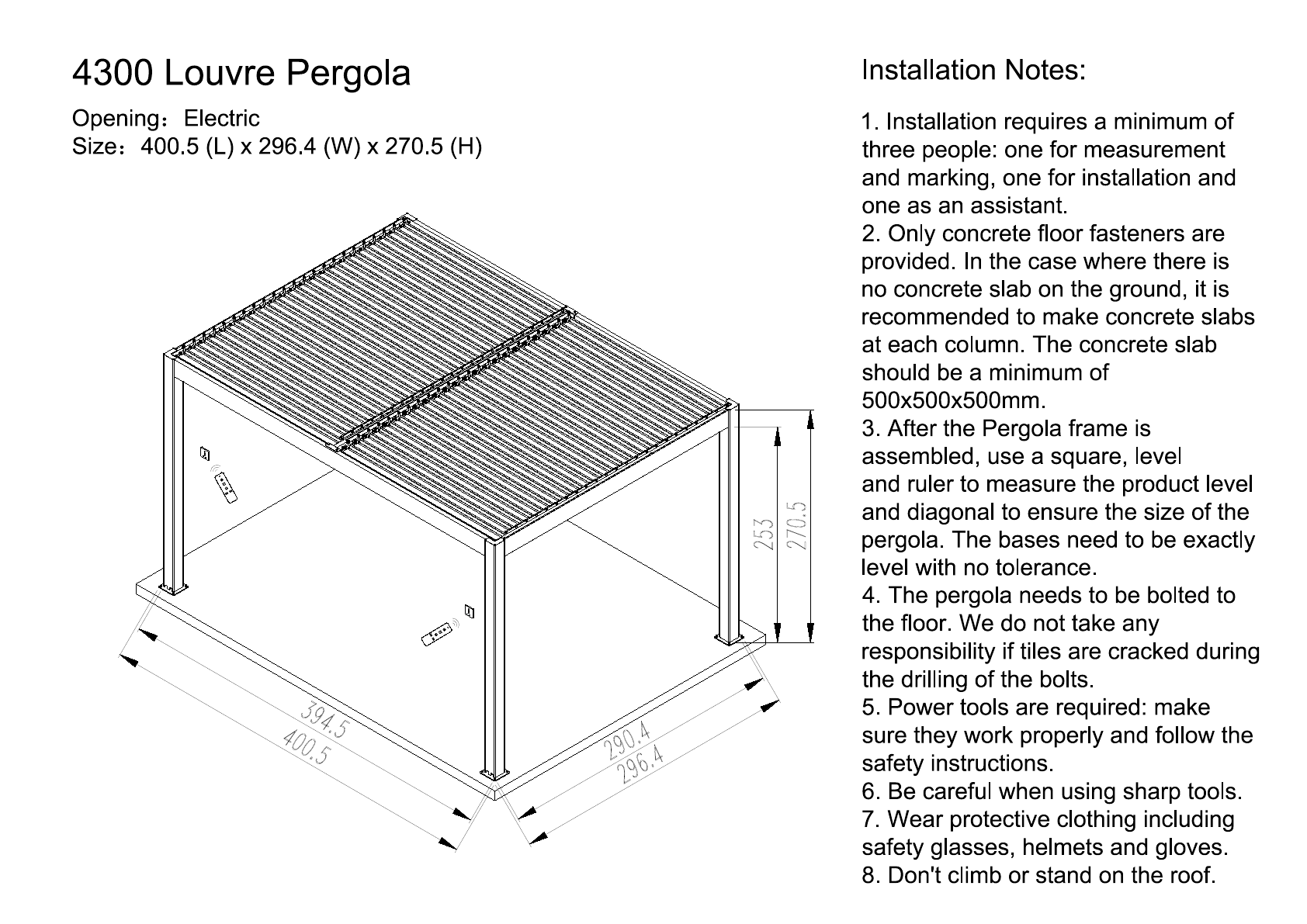
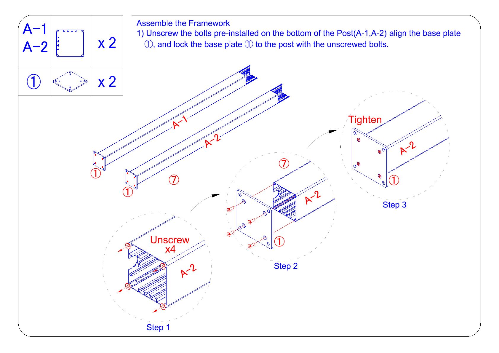
The pergola column must be positioned and fixed on a flat surface.
Do not lean on the column during the assembly phase.
Do not let children approach the scene during the assembly phase.
Don't be near pergola in a storm or typhoon.
Do not try to climb pergola under the influence of alcohol or drugs.
When using ladders or similar tools and power tools during the
assembly phase, be sure to follow the manufacturer's safety
recommendations.
Any hot tool, such as an electric drill, cannot be in contact with the
pergola profile.
Make sure there are no cables or other cables hidden underground
before positioning the column.
General Advice
This pergola has several components and it takes at least 90 minutes
to assemble. The pergola should not be positioned under a tree.
If you connect the column directly to cement or a similar base, use
the pre-punched holes on the supplied base.
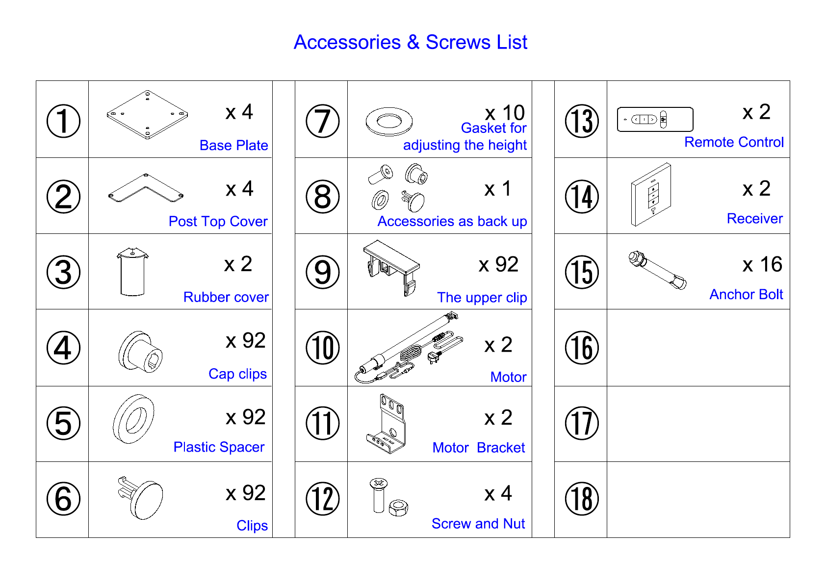
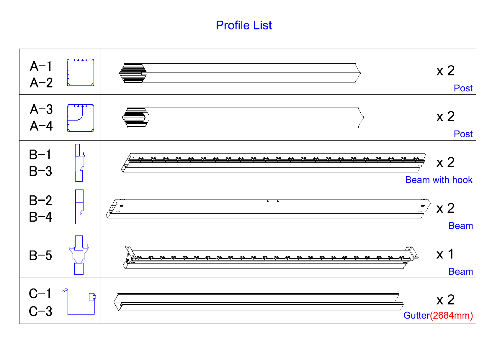
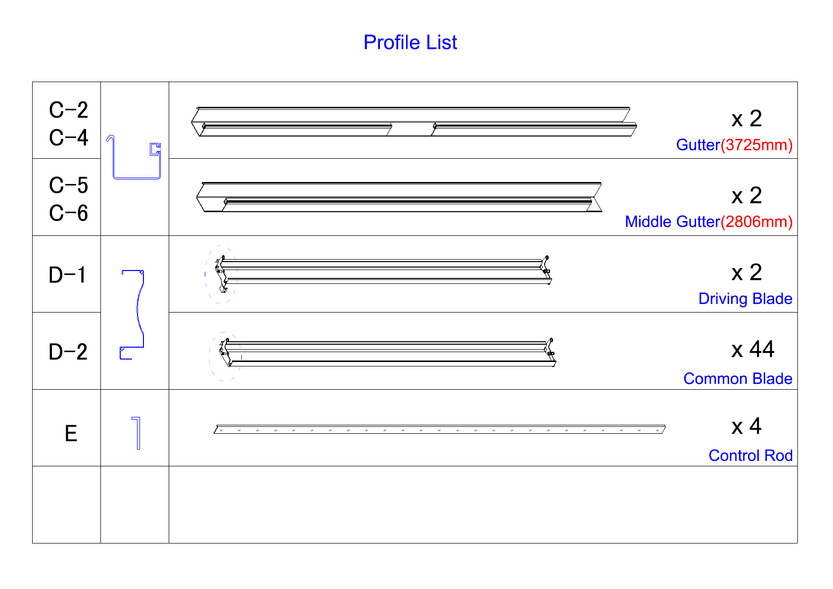
Check the number of profiles and fittings before assembly and use
them according to the list of profile fittings for easy assembly.
Put small pieces such as screws into a container to avoid loss.
Please pay attention to the position of the transmission on the beam
to avoid misplacement.
Regularly clean leaves, snow or other objects off the pergola.
Maintenance and Repair
To clean pergola, use a mild detergent and rinse with water. Do not
use acetone or abrasive cleaning products to clean the surface of the
aluminum profile.
·
·
·
·
·
·
·
·
·
·
·
·
·
·
·
·
·
·
·
·
Protection and Installation Tools
Protective Equipments:
1. Helmet
2. Gloves
3. Emergency first-aid kit
4. Protective glasses
Measuring Instrument:
1. Tape measure (5 metres or more)
2. Square ruler
3. Level
Tools:
1. 2 metre ladder (1.5 metres or more)
2. 13mm hex wrench
3. 17mm hex wrench
4. Electric drill
5. Electric drill bit (10 mm drill bit)
6. Marker or pencil
7. Rubber hammer
8. Silicon and glue gun
2

Accessories & Screws List
x 4
x 2
x 4
Rubber cover
Base Plate
①
②
③
④
⑤
⑥
⑦
⑧
⑨
⑩
⑪
⑫
⑬
⑭
⑮
⑯
⑰
⑱
Cap clips
Plastic Spacer
Clips
x 10
Gasket for
adjusting the height
Motor Bracket
x 2
Screw and Nut
x 4
Remote Control
x 2
Receiver
x 2
x 2
x 92
Post Top Cover
Anchor Bolt
x 16
x 92
x 92
x 1
Accessories as back up
Motor
The upper clip
x 92
3

Profile List
Post
x 2
Beam
x 2
Beam with hook
Post
x 2
A-1
A-2
B-1
B-3
B-2
B-4
B-5
Beam
x 2
x 1
A-3
A-4
C-1
C-3 Gutter(2684mm)
x 2
4

Profile List
Gutter(3725mm)
x 2
Control Rod
x 2
Driving Blade
D-2
Common Blade
x 44
x 4
x 2
D-1
C-2
C-4
C-5
C-6 Middle Gutter(2806mm)
E
5

A-3
The location
of the motor
The location
of the motor
A-1
A-4
B-2
C-6
B-1
C-1
C-4
B-4
C-3
B-3
A-2
C-2
C-5
B-5
Aluminum Profiles Lay Out Drawing
Installation notes:
1. To take the goods out of the
carton, 2 people are required to
lift them up, put them on the
ground lightly, and keep the
ground level and clean, better
to put a layer of cloth on the
floor to prevent the profile from
scratching.
2. The goods on the ground
should not be dragged, and
avoid collision with metal
surfaces or other uneven walls.
3. After setting up the whole set
pergola and test the pergola
well, then proceed to remove
all the surface film.
6

x 2
①x 2
Step 2
A-2
A-1
①
①
Step 3
x4
Unscrew
A-2
Tighten
A-2
①
①
Assemble the Framework
1) Unscrew the bolts pre-installed on the bottom of the Post(A-1,A-2) align the base plate
①, and lock the base plate ① to the post with the unscrewed bolts.
A-1
A-2
Step 1
⑦
⑦
A-2
7

①x 2
A-4
①
Step 1
Assemble the Framework
2) As shown, slide the motor plug from the top of the post into
the curved cavity on the inside of the post and pull it out
from the bottom. Unscrew the bolts pre-installed on the
bottom of the Post (A-3 , A-4),align the base plate ①, and
lock the base plate ① to the post with the unscrewed bolts.
x 2
A-3
A-4 ⑩
x 2
⑩
Step 2
Step 4 Step 3
x4
Unscrew
①
⑦
Tighten
①
⑩
⑩
⑩
A-3
①⑩
⑩
A-4
→
A-4
A-4
8

x 2
B-2
B-4
Assemble the Framework
3) As shown, unscrew the bolts pre-installed on the top of the Post (A-1, A-2, A-3,A-4,),
then fix the beam (B-2, B-4) on the two posts (insert the connectors at both ends
of the beam into the grooves of the two posts respectively). and tighten the bolts
on the beam.
Step 1
Tighten
x4
B-1
Step 3
A-3
→
→
→
→
B-2
B-4
A-2
A-1
A-3
A-4
Step 2
B-4
→
→
A-4
9

A-4
A-3
A-2
A-1 ②
②
②
②
B-3
B-1
x 2
②
x 4
B-1
B-3
Assemble the Framework
4) As shown, fix the beam with hook (B-1, B-3) on the two posts (insert the connectors
at both ends of the beam into the grooves of the two posts respectively).
5) Fixed the post top cover ② on the post with the unscrewed bolts
and tighten the bolts on the beam.
B-1
A-1
Step 1
Step 2
B-1
A-1
②
Step 3
B-1
x4
Tighten
A-1
10

⑮x4
⑮x4
⑮x4
Diagonal 90°
⑮x4
Step 2
⑮x4
Step 4
→
⑦
Step 3
⑮x4
It is the responsibility of the user to ensure that the pergola is fixed down. The manufacturer
is not responsible for damage caused by natural disasters or special events to the pergola (or its
accessories). Any pergola that is not fixed may be blown away and cause damage, and this responsibility
will not be attributed to the manufacturer. Check the pergola regularly to ensure it remains stable and firmly attached to
the ground. A pergola that detaches from its position and incurs or causes damage will not be covered under warranty.
Note:
Before fixing the base plate, it is
necessary to ensure that the
diagonals of the 4 posts
are the same length. When the ground is uneven, use
gasket (under the base) to adjust.
x 10
⑦
x 16
⑮
Fix Pergola to the Ground and Wall
1) Use the 16 Anchor bolts provided, if the ground is not concrete floor.You will need to
find another solution to bolt your pergola down onto your desired surface.
2) Move the pergola to the appropriate i
nstallation position, then mark the
position of the two posts with the
pencil,remove the pergola,and
use the electric drill to make
16 holes according to the mark.
Move thepergola back to the
position and secure the base
plate with the anchor bolt ⑮.
11

x 2
⑩
⑪
x 2
x 2
C-1
Gutter length:
C-2/C-4 > C-5/C-6> C-1/C-3
Mounting Motor
1) As shown, firstly install the Motor ⑩ on the Motor Bracket ⑪
and then insert them into the long gutter (C-1,C4).
C-3
Preinstalled
⑩
⑪
Step 1
Step 2
Step 3
⑩
⑩
⑪
⑪
C-3
→
⑩
C-3
C-1
12

C-1
~
C-4
x 4
Installing the Gutter
1) As shown, hook the gutters to the beam (the gutter has a hook, the beam has a groove).
Gutter length:
C-2/C-4 > C-5/C-6> C-1/C-3
Step1
Step2
C-2
C-3
C-2
C-3
→
C-1
Step3
C-4
C-3
→
C-2
13

x 1
B-5 Assemble the Framework
1) As shown, fix the Middle Beam B-5 on the framework with bolt.
B-5
B-5
→
Step 1
Step 2
B-5
14

C-5
x 2
Installing the Gutter
1) As shown, hook the gutters to the beam (the gutter has a hook, the beam has a
groove).
C-6
C-6
C-5
B-6
Step 2
B-6
B-5
Step 1
15

Not available Increase the Waterproof Performance of Pergola
1) The pergola product itself is waterproof, so the manufacturer does not
provide a sealant. Sealing can be done at the owner’s discretion to
increase the pergolas durability. Sealing position: the inside of the profile
joint and the joint between the gutters .
16

Installing Louvre Blades
1) As shown, the Driving Blade D-1 clicks directly into the groove. Then use the fixing the
cover ⑨ to cover.
x 2
D-1
x 4
⑨
Step 2
Step 1
D-1
D-1
7th groove
D-1
D-1
→
→
⑨
→→
D-1
⑨
17

⑩
⑪
⑫
Mounting Motor
2) As shown, unscrew the bolts on the beam, move the motor close
to this position and fix the motor bracket ⑪ to the beam with bolts.
3) Connect the Motor ⑩ arm bracket to the end cap of Driving Blade D-1.
⑩
⑪
⑫
x 4
x 2
x 2
Tighten
Step 1
⑩
Unscrew
x3
Tighten
D-1
Step 3
⑫X2
⑩X2
⑪
→
⑩
⑩
18

Step 2
→
③
Local Plug & Socket
1. Do not put near water
2. Plug: 10A, 110 - 240V
Step 1
Installing Wire
1) As shown in the picture, when arranging the motor wires, please put
the wires can be plugged into the rubber cover ③, and then the rubber
cover can be hooked on the beam (the rubber cover has hooks and the
beam has grooves)
x 2
③
⑩
x 2
⑩
19
Table of contents
Other Vortex Tent manuals
Popular Tent manuals by other brands

skandika outdoor
skandika outdoor SKALAND 5 Setup Instruction

DARCHE
DARCHE AIR-VOLUTION AT-4 instructions

Grizzly Outdoor
Grizzly Outdoor 4 meter Series Assembly instruction

Big Sky
Big Sky Moon View Wisp 1P quick guide

Kampa
Kampa Privvy Installation and operating manual

SunnyTent
SunnyTent Circular Series manual

skandika outdoor
skandika outdoor DAYTONA 6 Setup Instruction

Yardistry
Yardistry YM12830 installation instructions

Khyam
Khyam KAMPER SLEEPER Pitching & Striking Instructions

Quest Leisure Products
Quest Leisure Products Falcon Air Porch Awnings instructions

ShelterLogic
ShelterLogic 25730 Assembly manual & parts list

StarEcho
StarEcho PT0148A2S Assembly instructions