- 3 -
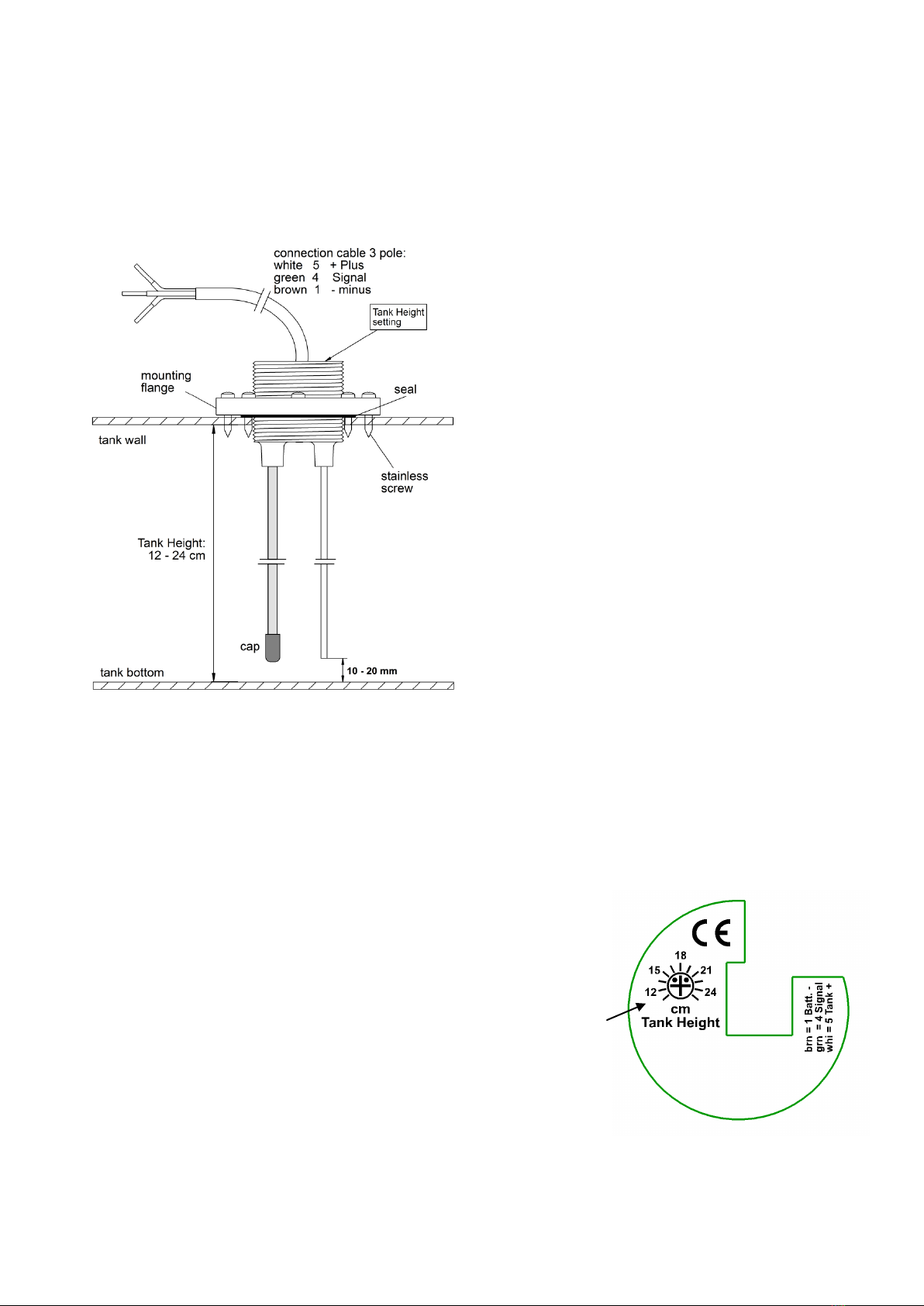
Configuration of Connections:
Colour Connection No. Tank Display Function Connection No. Plug-type Connector
White 5= Tank +(Plus) + Operating Voltage, from Display Unit Connection 53
Green 4= Tank Signal Measuring Signal to Display Unit Connection 4, 0…2.2 V 2
Brown 1= Battery - - Operating Voltage (Minus) or Body Ground, 11
Recommended cable cross-section for all cables: 0.5-1 mm²
The tank electrode K-WC is protected against any kind of reverse battery. It is recommendable to use connection cables of
different colours to avoid malfunctions due to mixed up connections.
Install the delivered 3-pole tip jack with inserted cassette at an easily accessible location in the vehicle's mounting slot and
establish the connections (screwable) to the display units.
Also with inserted cassette, the transmitter connection cable can now be shortened to a length, which is easy to handle.
How to connect the 3-pole connector to the transmitter:
The connector is equipped with self-contacting cutting-clamping contacts (solderless). Proceed according to the enclosed
instructions, paragraphs 1-6:
1. Push the female connector on the cable, strip the insulation of the cable 35-40mm. DO NOT strip the 3 single
conductors!
2. Insert the cable until the stripped insulation into the clamping part.
3. Open the small lateral flap, insert brown = 1 and bend it. Close flap. Now insert white in groove 3 end bend it,
insert green in groove 2 and bend it.
4. Not required (cable shield)
5. Not required (cable shield)
6. Press the cable clamp together and turn it into the plug housing until tongue/groove fits. Insert the cable clamp as
far as possible into the plug housing and screw on the female connector (in doing this, the contacts are
established).
As soon as the display unit has been installed according to the operating manual, the battery can be connected.
Start-up and Adjustment:
Set the measured tank height at the adjuster "Tank Height" on the display for 100 % "FULL".
The functions of the display can now be tested with several water levels in the cassette or in a bucket being filled with
water by withdrawing the tank electrode.
Fine adjustment of the set water depth can be corrected or changed at any time with full tank.
Final Installation:
Insert the delivered packing ring into the mounting hole and insert the tank transmitter from above into the mounting hole,
so that the packing ring is placed between the cassette and the casing flange of the transmitter. Now insert the mounting
ring and screw it down to the cassette using the 8 delivered stainless steel screws.
While handling the cassette, the connector plug is held and thus protected by the delivered clip. Place the self-adhesive
holding clip at a suitable location on the cassette.
In case of underfloor installation of the tank below the vehicle, the adjuster must be protected with a permanently elastic
sealant against aggressive environmental influences (de-icing salt etc.).
Tips and Tricks:
No reaction of display:
a. Wire 4 = Tank Signal Withdraw by way of trial and direct it to connection "5": (Plus):
The display should increase to 100 %! Otherwise:
b. Battery connection or fuse defective check!
c. Wire 5 =Tank Plus interrupted check!
d. Wire 4 = Tank Signal: Short-circuit to Minus / Ground check!
Constant display of 100 % on the display unit:
a. Wire 4 = Tank Signal Withdraw it and direct it to ground: Display must be empty!
b. Wire 1 = Battery Minus / Ground is interrupted or does not have any contact due to paint residues at the
body check!
c. The insulated stick probe is contacting water: The silicone cap is leaky or dropped off, the insulation of the cable probe
is damaged check!
Indication Errors:
a.
Furring of the insulated stick probe by stuck solids in the feces tanks and sewage water tanks rinse tank!