Votronic 100 S User manual

- 1 -
Installation and Operating Manual
LCD Battery Computer 100 S with 100 A Smart Shunt No. 1263
LCD Battery Computer 200 S with 200 A Smart Shunt No. 1266
LCD Battery Computer 400 S with 400 A Smart Shunt No. 1269
The Votronic LCD Battery Computer S is designed for exact measuring of the charging state of board batteries
in caravans, campers, boats, special purpose and intervention vehicles.
Please read the mounting instructions and the operating manual including the safety regulations
completely prior to starting connection and start-up.
The VOTRONIC LCD Battery Computer S calculates the exact charging state of the battery and displays the
charging state like a "fuel gauge for the battery". In contrast to simple ampere-hour meters, the residual
capacity will be determined in ampere-hours (Ah) or the residual charge in % by means of programmed
battery-characteristic and will be displayed as state of charge. Apart from this, the LCD Battery Computer S
provides the display of the battery voltage (V) of a second battery (starter battery).
The smart-shunt, which is provided with the unit, is extraordinary robust, very exactly and shows extreme
overload capacity (refer to "Technical Data"). It is equipped with a programmable output to remote control a
main-switch which connects or disconnects consumer loads or further energy supply units, depending on the
charging state of the battery.
Operation LCD Battery Computer S
Key 1: Next page of the battery computer display,
manual disconnection of the terminal (3s).
Key 2: Previous page of the display, manual
activation of the terminal (3s).
Key 3: Display on/off.
Set (3s)
Activation, Deactivation
The unit is optimized for extremely current saving operation
and offers three operation modes.
Stand-by: During stand-by mode the display is empty. If the
terminal is activated, "ON" will be displayed, and if it is
switched-off, "OFF" will be displayed.
Display with and without illumination: As soon as the LCD
Battery Computer S is operated, the display illumination will
be switched-on and will remain activated for 3 minutes. If
there is no operation during this time, the illumination will be
switched-off automatically. Due to power saving, the
illumination duration is just a few seconds while the
“Terminal” is off.

- 2 -
Displays Battery Computers
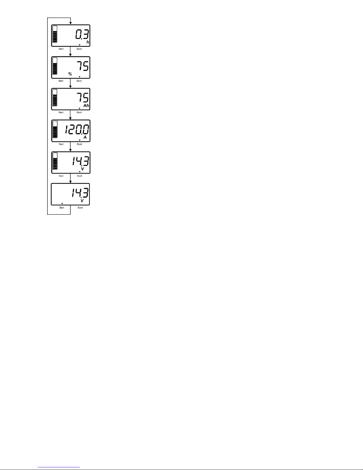
Use the keys 1 and 2 to display the next or previous page of the measuring and display
values.
Voltage:
Display of the voltage of the board battery (B1) and of a second battery (B2), such as the
starter battery, is possible.
The marking triangles at the lower edge of the display point to the displayed battery.
Current:
The current display informs of the current load or charge of the battery. The display shows
the instantaneously measured current rate flowing out of the battery.
If the current flows into the battery, the display will show a positive current value and the
charging symbol "CHARGE". If the current flows out of the battery, it is negative, and the
value will be shown with a preceding negative sign.
Capacity Display:
The microcomputer-controlled measurement accurately counts each ampere-hour (Ah) of
capacity during charging and discharging, even in splits. The automatic evaluation of the
battery load is effected by means of the programmed characteristic lines of the battery. So,
a current rate of e. g. 100 Amperes represents an inferior load for a 600 Ah battery, while
this is an extremely high load for a 70 Ah battery. Correspondingly, the large storage
battery provides almost its full capacity, but the small 70 Ah battery only 42 Ah or 60 % of
the indicated nominal capacity, at best.
The result is a correct indication of the available capacity in the battery (residual capacity,
charging state), such as it is known from a "fuel gauge". It is a matter of course, that also
the self-discharge of the battery in case of long downtimes will be considered. During
charging of the battery, the full charging state will be recognized automatically, and it will be corrected, if
required. Depending on the quality of the used charger, the charged capacity may be between 80 % and
100 %. The capacity of the board battery will be displayed in ampere-hours (Ah) and as percentage (%) of the
nominal capacity. The bar graph at the left margin of the display represents the capacity in steps of 10 %.
Display of the Remaining Time:
The remaining time will be calculated from the residual capacity (up to the adjusted switching-off threshold)
and of the actual current. In case of very high current rates, an adaption to the capacity value of the battery
will not be effected. Thus, in case of high current rates, the display of the remaining time is only of informative
character. It is calculated according to the following formula: (Capacity switching-off threshold - actual
capacity) / actual current.
If the battery does not supply current, a calculation of the remaining time is, of course, not possible. Now the
sign -.- will be displayed.
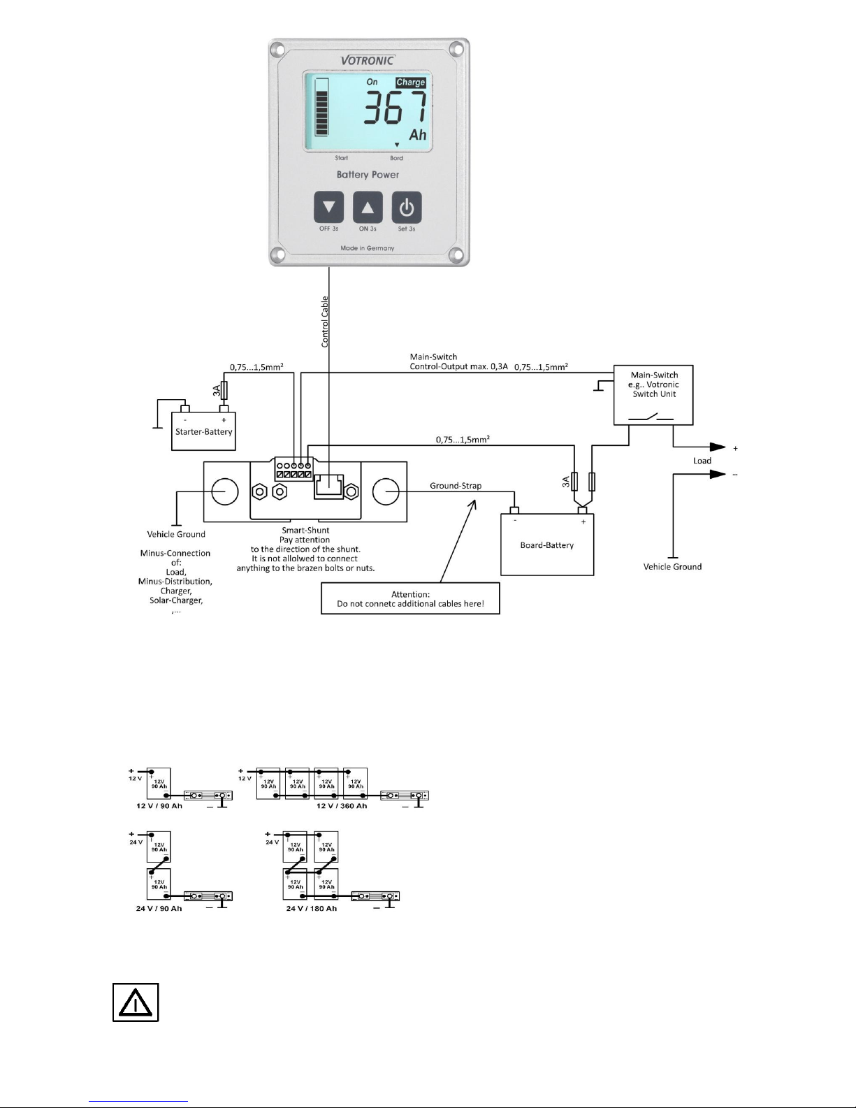
Installation and Connection:
All terminals are designed in such a way, that end-type terminals are not required. The cable cross-sections
can be drawn from the plan. Since fuses serve as cable protection, they must be positioned as close as possible
to the battery.
Display and Control Panel
Choose a central and easily accessible location in the living area for installation of the display. This will
facilitate the legibility of the information and the operation of the functions. The clear width of the cutout is at
least 72 x 66 mm. If possible, the rear cutout opening should be covered with electrically nonconducting
material to ensure efficient protection of the electronic system and full utilization of the storage space, which
might be located behind. Ensure the ventilation of the electronic system.
The display will be connected to the smart shunt via a 6-pole control cable of 5 m length. The connection is
executed ready to be plugged in, and the cable should be laid according to the safety instructions. If the length
of the control cable is not sufficient, an extension of the control cable (5 m), order No. 2005, is available as
accessory. The total cable length is then 10 m. Faultless operation is only ensured, if the delivered control
cable, as well as the original Votronic control cable extension are used.

- 3 -
Smart Shunt
The smart shunt measures the battery voltage as well as the current for determination of the residual capacity
(level) of the battery. Furthermore, it can measure the voltage of the starter battery, and it is equipped with a
terminal for control of a main switching relay, such as the Votronic Switch Unit 40.
Battery Systems:
Any battery current should flow over the smart
shunt. Therefore, it is to be installed directly near the
battery (batteries). Correct calculation of the actual
battery capacity is only possible, if all currents are
detected correctly by the smart shunt.
Ground straps at the connecting screws M8 of the
smart shunt are to be screwed in such a way, that
one connection is connected to the negative pole of
the battery and the other one with the car body. The
connections at the negative pole of the battery and
at the body / ground should not be mixed up (see connection plan). Otherwise, a charge is measured as
discharge and vice-versa.
Never connect anything to the brass screws of the electronic system of the smart shunt.
The connections at the smart shunt should always be tightened firmly to avoid any transition
resistance. Permanent high load might result in heating of the smart shunt.
Except of the smart shunt, no further connection (e. g. of consumers or charging devices) should
exist at the negative pole of the battery or at the negative pole of the complete battery system!

- 4 -
A freely programmable terminal is at disposal. At the touch of a button, this terminal can be used as main
switch for consumer loads or for capacity disconnection.
In active condition (ON), the battery voltage (+12 V or +24 V) is here at disposal, and it is protected against
overload by means of a self-resetting fuse 0.3 A. The terminal can be reinforced by an interposed switching
relay.
Due to the high current consumption of standard relays, we recommend to use the switching components
"Votronic Switch Unit" (see accessories).
They allow a high switching capacity with very low own consumption (only a few mA). Thus, they are
particularly suitable for continuous operation without any load of the battery.
The electronic system of the smart shunt can be protected by means of a cover for the smart shunt (order No.
2023), which is available as option.
Except of the measuring shunt, no further connection should exist at the negative pole (-) of the
battery or at the negative pole of the entire battery system!
This concerns all consumer loads, the body ground and all charging units (chargers, solar chargers,
charging converters etc.)!
Initial Start-up
The smart shunt is ready for operation, as soon as all electric connections at the smart shunt and the display
panel are made. Besides, the following basic settings must be made compulsory.
Basic Setting:
The nominal capacity of the board battery must be set.
The used battery type and its nominal voltage must be set.
The switching-off thresholds and switching-on thresholds can be adapted.
The nominal capacity is indicated in Ah, and it is imprinted on the battery. If several Ah-values can be found,
use the value ....Ah (20 h). If several batteries have been combined to a 12 V battery system, add the Ah
values. Total capacity for 2 batteries at 110 Ah is 220 Ah. This value -220 Ah- must be set.
After the basic setting, the battery must be charged using a suitable charger (in case of mobile
homes using the existing board charger) for a duration of 24 h. This is absolutely required, so that
the battery computer is able to recognize 100 % full charging required for starting. If the smart
shunt loses its voltage supply (battery disconnected etc.), also proceed as described above.
After adjustment of the battery capacity and after loss of the supply voltage, the residual capacity will be
estimated automatically by means of the battery voltage. After that, the battery must imperatively be charged
for at least 24 hours with a suitable automatic charger to ensure correct display of the capacity. Only when the
battery had been fully charged, the system adjusts itself to "its" battery, and the display will show 100 % or the
residual capacity of the battery in Ah. The initial settings and the full charging of the battery are absolutely
required to ensure proper capacity indication, and it must be repeated whenever the unit or the battery had
been disconnected!
Settings Battery Computer:
The menu for settings is called by pressing and holding key 3 for more than 3 seconds.
The keys 1 and 2 are used to set the values.
In the menu, the key 3 is used to save the setting and to jump to the next menu item. If no key had been
pressed within 10 seconds, the display returns to standard operation.

- 5 -
How to set the Battery Type and the System Voltage
The possible battery types and their number for setting in the menu can be drawn from the table. If the value
is not accepted, the setting can be repeated.
Type
Volts U1
approx.
Set Value
12 V System
Set Value
24 V System
Lead-Acid/Lead-Acid
14.4
24
124
Gel
14.4
53
153
AGM-14.4
14.4
34
134
AGM-14.7-14.8
14.7-14.8
47
147
LiFePo4 13.9 V
13.9
89
189
LiFePo4 14.2 V
14.2
82
182
LiFePo4 14.4 V
14.4
84
184
LiFePo4 14.6 V
14.6
86
186
LiFePo4 14.8 V
14.8
88
188

- 6 -
Adjustment of the Nominal Capacity:
The nominal capacity is indicated in Ah, and it is imprinted on the battery. If several Ah-values can be found,
use the value ....Ah (20 h). If several batteries have been combined to a 12 V battery system, add the Ah
values. Total capacity for 2 batteries at 110 Ah is 220 Ah. This value -220 Ah- must be set.
Adjustment of the Terminal Switching-on Threshold:
Here, the switching threshold for the automatic activation of the terminal can be adjusted.
The switching threshold can be set to 101 %. Thus, an automatic activation will never be reached.
Adjustment of the Terminal Switching-off Threshold:
The same is true as for the switching-on threshold. An automatic disconnection can be prevented by setting
this value to 0 %.
The memories for the lowest and the highest voltage rates and capacity rates can be reset. Rest them by
pressing and holding the keys 1 and 2 simultaneously for 3 seconds. The value will be deleted and „--.-„ will be
displayed.
A counter indicates the time in hours, which elapsed from the last 100 % full charging.
Adjustment of the Background Illumination:
The background illumination can be adapted from bright to completely dark in steps of 10 % according to the
requirements.
General Information:
Once a year:
Check the connecting screws at the measuring shunt for tightness.
Check the connection cable for correct contact and damage.
Aged batteries:
Lead batteries are subject to wear, which will be growing with the age of the battery, the number of
charging/discharging cycles, the rate of discharge (frequent deep discharge) and other factors, such as
extreme temperatures, vibration etc. This results in a reduction of the available capacity.
The LCD Battery Computer S is able to consider this loss of capacity for calculation within certain limits.
However, we recommend to correcting the set nominal capacity to a lower value (e. g. 5 %, depending on the
battery type and the operating condition 2-10 %), once a year.
Cleaning:
We recommend to use a damp microfibre cloth with pure water or, if required, with water with a few soap.
Take care, that no liquid flows along the display screen or the edges of the front panel.
Never use solvents, aggressive household cleaners, and scratching or abrasive agents or objects to
clean the front panel and particularly the display itself.
Trouble-shooting:
No display at all:
Reverse battery: Check!
Battery is deeply discharged, below 7 Volts: Recharge immediately!
Connection cable is interrupted, damaged, or it is not inserted: Check!
The display does not show 0.0 A after disconnection of all consumers and chargers:
Check, if latent current consumers are existing!

- 7 -
Safety Instructions:
Safety Regulations and Appropriate Application:
The LCD Battery Computer S with Smart Shunt has been designed according to the
valid safety regulations.
Appropriate application is restricted to:
Control of commercial types of lead storage batteries (lead-acid, gel, AGM), as well as LiFePo4, of the
indicated nominal voltage and of connected consumers in fixed installed systems.
With observation of the capacity limits of the smart shunt (see "Technical Data").
Together with the supplied smart shunt.
Technically faultless condition.
Installation in a well-ventilated room, protected from rain, humidity, dust, aggressive battery gases, as
well as in an environment being free from condensation water.
With a rear insulating cover of the display unit.
Never use the unit in locations where the risk of gas or dust explosion exists!
Open-air operation of the unit is not allowed.
Cables are always to be laid in such a way that damage is excluded. Observe to fasten them tightly.
Never lay 12 V (24 V) cables and 230 V mains supply cables into the same cable conduit (empty conduit).
Check live cables or leads periodically for insulation faults, points of break or loosened connections.
Occurring defects must be remedied immediately.
The unit is to be disconnected from any connection prior to execution of electrically welding or work on
the electric system.
If the user is not able to draw from the present manual, which characteristic values
are valid for a unit or which regulations are to be observed, a specialist is to be consulted.
The user/buyer is obliged to observe any construction and safety regulations.
Keep children away from the batteries and the smart shunt.
Observe the safety regulations of the battery manufacturer.
Ventilate the battery room.
Always use the same car fuses for replacement!
The unit is not equipped with parts, which can be replaced by the user.
Non-observance may result in injury or material damage.
Never use solvents or aggressive household cleaners for cleaning of the display!
The warranty period is 24 months from the purchase date (against presentation of the sales slip or
invoice).
The warranty will be void in case of any inappropriate utilisation of the unit, if it is used beyond the
technical specification, in case of improper operation or external intervention. We do not assume any
liability for any damage resulting hereof. The liability exclusion is extended to any service being executed
by third, which has not been ordered by us in writing. Service is to be effected exclusively by VOTRONIC,
Lauterbach.

- 8 -
Technical Data:
System:
Nominal Voltage Board Battery
12 V/ 24 V
Operating Voltage Range Board Battery
8...32 V
Current Draw
8...60 mA, depending on illumination
Battery Types
See Table "Battery Type"
Nominal Voltage Starter Battery
12 V/ 24 V
Operating Voltage Range Starter Battery
8...35 V
Switching Current Terminal Main Switch
max. 0.3 A
Ambient Conditions, Humidity of Air:
max. 95 % RH, no condensation
Display Unit (LCD Display):
Technology
LC Display with specific segments,
legible with and without illumination,
Membrane keyboard
Representation Surface
49 x 28 mm
Lighting
white LED
Dimensions
85 x 80 x 24 mm
Assembly Dimensions Opening Electronic
approx. 72 x 66 mm
Weight
approx. 55 g
Smart Shunt:
100 A
200 A
400 A
Max. Admissible current Smart Shunt:
Nominal Current
100 A
200 A
400 A
Max. Current 15 Minutes
150 A
300 A
600 A
Max. Current 7 Minutes
200 A
400 A
800 A
Max. Current Short-time
450 A
900 A
1800 A
Weight
240 g
240 g
245 g
Dimensions Smart Shunt
135 x 32 x 44 mm
Ground Strap:
Cross-Section
25 mm²
35 mm²
75 mm²
Weight
100 g
140 g
360 g
Declaration of Conformity:
In accordance with the provisions of Directives 2014/35/EU, 2014/30/EU, 2009/19/EC, this
product complies with the following standards or normative documents:
EN55014-1; EN55022 B; EN61000-6-1; EN61000-4-2; EN61000-4-3; EN61000-4-4;
EN62368-1; EN50498.
The product
must not be
disposed of in
the household
waste.
The product is RoHS compliant.
It complies with the directive
2011/65/EU for Reduction of
Hazardous Substances in electrical
and electronic equipment.
Delivery Scope:
1 pc. Battery Computer (Display)
1 pc. Smart Shunt 100 A, 200 A or 400 A
1 pc. Ground Strap
1 pc. Control Cable, Length 5 m
4 pcs. Fastening Screws
1 pc. Operating Manual
1 pc. Drilling Jig
Available Accessories:
Control Cable Extension, 5 m Length Order No. 2005
Casing Order No. 2024
Switch Unit 40 Order No. 2071
Switch Unit 100 Order No. 2072
Battery Protector 300 (Switch Unit 300) Order No. 3084
Subject to misprints, errors and technical modification without notice.
All rights reserved, particularly the right of reproduction. Copyright VOTRONIC 07/18.
Made in Germany by VOTRONIC Electronic-Systeme GmbH & Co. KG, Johann-Friedrich-Diehm-Str. 10, 36341 Lauterbach/GERMANY
Phone: +49 (0)6641/91173-0 Fax: +49 (0)6641/91173-20 E-mail: [email protected] Internet: www.votronic.de
Other manuals for 100 S
1
This manual suits for next models
2
Table of contents
Other Votronic Measuring Instrument manuals
Popular Measuring Instrument manuals by other brands

Foxtech
Foxtech TEMPHAWK user manual

A.W. Sperry Instruments
A.W. Sperry Instruments DSA-500 operating instructions

Novasina
Novasina PascalMaxx +/-50Z operating instructions

Tegam
Tegam R1M-A Operation and maintenance manual

AGSTECH
AGSTECH SIS LZ Series quick start guide

EG&G
EG&G ORTEC 553 Operating and service manual

TPI
TPI 777 quick start guide

Analog Technologies
Analog Technologies ALDD28V5A401 quick start guide

Radiodetection
Radiodetection C.A.T3V and Genny3 user guide

scigiene
scigiene SP-840006 instruction manual

Vision & Control
Vision & Control TO44/6.2-150-V-B Instructions for use

CONDTROL
CONDTROL MicroX user manual