VREDO DZ SUPERcompact Series User manual

Operator Manual Overseeder
The best in the eld
HL_DZ-SUPERcompact _10-2017_ 03_EN
S
U
P
E
R
C
o
m
p
a
c
t
,

HL_DZ-SUPERcompact_10-2017_03_EN 2

HL_DZ-SUPERcompact_10-2017_03_EN 3
OPERATOR MANUAL
DZ SUPERcompact series
(Original instruction)
This operatorsmanual is part of the DZ SUPERcompact overseeders.
Serial Number:____________________ Production year:_______
Options:
□ Chassis 3-Point hitch Trailer version
Supplier/manufacturer: VREDO Dodewaard BV
Welysestraat 25a
6669 DJ DODEWAARD
P.O. Box 35
6670 AA ZETTEN
The Netherlands
T: +31 488 411254
F: +31 488 412471
W: www.vredo.com
Distributor / Dealer:
(stamp)
Copy or reproduction of this manual or parts thereof, in whichever way, is not permitted without prior writ-
ten authorization from Vredo Dodewaard BV.

HL_DZ-SUPERcompact_10-2017_03_EN 4

HL_DZ-SUPERcompact_10-2017_03_EN 5
Table of contents
1. Introduction .............................................................................................................................................7
2. Safety requirements ................................................................................................................................8
3. Instructions for use..................................................................................................................................9
3.1. General .................................................................................................................................................. 9
3.1.1. Functions of the control handles ...............................................................................................10
3.2. Instructions for use .............................................................................................................................12
3.3. Calibrate the dosing system ...............................................................................................................14
3.3.1. Adjustement according to the dosingchart...............................................................................14
3.3.2. Adjustment by calibration ..........................................................................................................15
3.4. Adjustment of the town overseeder...................................................................................................18
4. Dosing charts.........................................................................................................................................18
4.1. Dosing chart for Vredo overoverseeder. ............................................................................................18
4.2. Tips & Tricks ........................................................................................................................................20
5. Options ..................................................................................................................................................20
6. Maintenance..........................................................................................................................................21
6.1. Visual inspection .................................................................................................................................21
6.2. Tightening torque for bolts and nuts .................................................................................................22
6.3. Lubrication...........................................................................................................................................22
7. Problem solving .....................................................................................................................................23
7.1. Overseeder related problems.............................................................................................................23
7.2. Pulled overseeder related problems ..................................................................................................24
8. Technical data .......................................................................................................................................25
9. Photo’s...................................................................................................................................................26
10. Warning signs ........................................................................................................................................29
10.1. Meaning of warning signs ..................................................................................................................30
11. Hydraulic plan........................................................................................................................................31
12. Electrical diagram ..................................................................................................................................32
12.1. Raise –lower frame pulled overseeder.............................................................................................32
12.2. Road light diagram..............................................................................................................................33
13. Instructions............................................................................................................................................34
14. EC-certificate .........................................................................................................................................35

HL_DZ-SUPERcompact_10-2017_03_EN 6

HL_DZ-SUPERcompact_10-2017_03_EN 7
1. Introduction
This user manual is intended to provide information for the user of a VREDO overseeder and will particularly
focus on the most important points concerning use and maintenance. This document will therefore never
be complete and may, after possible changes to your machine, not be completely correct anymore. For this
reason no rights can be derived from the following description.
The VREDO Super Compact overseeder has been specifically developed for the overseeding and reseeding
of existing sports fields and golf courses where the grass is too thin or there are bald patches.
Each coulter element is spring suspended, allowing it to follow the contours of the ground and achieving an
even sowing depth.
The design of the seed delivery tubes ensures that the seed is placed INTO the slit with good soil contact.
Prior to the machine being installed or used, this manual must be carefully read through to become familiar
with the machine’s action, operation and maintenance.
Breakdowns are often the result of incorrect operation or insufficient maintenance.

HL_DZ-SUPERcompact_10-2017_03_EN 8
2. Safety requirements
Replace all warning indications on the tank that are damaged or unreadable (see chapter 7), and keep all
stickers with safety requirements free of mud and contamination.
Check, and repair if needed, the function of all lights on the machine before entering public roads.
Get out ignition key from driving vehicle before attempting any service to the overseeder and observe the
instructions in this manual.
Fit the supports to the frame and lock them with the safety pins or set the 3-point linkage in lowest position
or block it by props or hang it by chains or hoisting belt.
For trailed machines with hydraulic drawbar and wheel set, ensure that the mechanical locking devices are
in place before attempting any work underneath (photo 7 no. 6).
Before hitching off the machine, ensure that the support stands are in place (photo 1 no. 1).
WARNING! The discs are very sharp.

HL_DZ-SUPERcompact_10-2017_03_EN 9
3. Instructions for use
3.1. General
The 3 point linkage types are raised on the tractor lift arms for road transport. Ensure the maximum road
transport width is not exceeded in your country. Also ensure that the sway blocks or chains are in place to
prevent the machine swinging when lifted.
See drawing below for all technical data for attachments.
Towed machines with a drawbar eye with a hole of ø38
are fitted as standard to the drawbar.

HL_DZ-SUPERcompact_10-2017_03_EN 10
Together with every overseeder 2 supports are enclosed. (See picture 1 no 1). When disconnecting the ma-
chine from the tractor, and parked, always the supports have to be placed in good order to prevent the
overseeder from tipping. Once the overseeder is hanging behind the tractor, the supports can be fitted to
the head in the existing conduits.
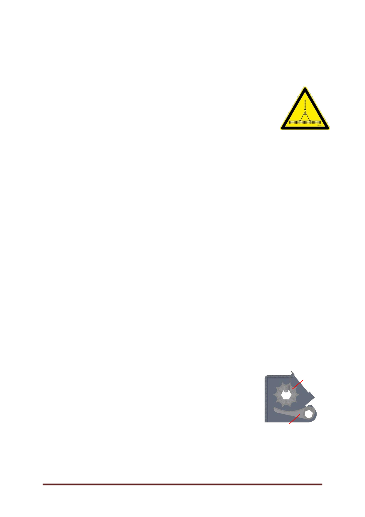
Moving the overseeder is done safe and easy in the 3-point hitch of a tractor. If such is
not ready for use, transport is possible by use of a correct chain linked to the top-link of
the overseeder, as indicated by a safety sticker near the mounting point.
For moving the machine all national and local safety regulations have to be respected,
take in account the weight of the seeder. Machine weight is to be found in chapter 5
“technical data”.
Before mounting, demounting, repair, service or other works to the applicator always stop the driving (trac-
tor) engine. Fit the supports to the frame and lock them with the safety pins or set the 3-point linkage in
lowest position or block it by props or hang it by chains or hoisting belt or fit the cylinder blocks when this
concerns the towed machine.
Before setting in operation again, check carefully if all fastenings are fitted properly and no tools or persons
exist on or between the machine; remove all blockages.
Take care that when attaching the tractor is positioned straight in line with the seeder, with the threepoint
hitch down. Before lifting the linkage to pull the balls into the claws of the lift arms, always first fasten the
top linker between vehicle and applicator. In case the linkage should lift up to much, than there is less risk
that the applicator will fall down because the top linker will hold it to prevent an accident.
Take care that the applicator is fixed properly in the linkage of the pulling vehicle. The safety hooks of the
claws must fit properly around the balls and the top linker has to be fastened.
In a towed machine, checks must be carried out to ensure that the drawbar eye is properly secured around
the hitch pin and that this is properly secured to prevent it from slipping off.
To enable hydraulic lifting and lowering of the towed machine, a double-action hydraulic valve is required
on the tractor with a closed central position. The quick-detachable couplings that are used are 1/2" Male
(Vredo no. A829.22).
In order to electrically power the machine we advise placing a 3-P coupling socket (to be ordered under no.
A453.91) at the pulling vehicle with a separate feed which is secured with ±5A. You can also feed the ma-
chine through the lighting. There is a coupling socket at the lighting connector. In this case the lighting has
to be switched on for the machine to work correctly and the lighting has to be secured more heavily.
3.1.1. Functions of the control handles
1. Bottom flap handle (photo 3 no. 1 & 2)
With the bottom flap handle the position of the bottom flap can be adjusted in
respect to the camwheel. The adjustment of this handle depends on the seed-
size.
When sowing e.g. standard Ryegrass it should be in smallest position. For
larger seeds according to the size of the seed the handle can be adjusted into
another 3 positions. It can also be “opened up” to empty the seed hopper.
ATTENTION! Only close the bottom flap when the seed hopper is empty.
bottom flap
cam wheel
dispenser hop-
per

HL_DZ-SUPERcompact_10-2017_03_EN 11

HL_DZ-SUPERcompact_10-2017_03_EN 12
2. Seed rate setting (photo 2 no. 2)
The Variator adjusts the seed rate (kg/ha.). With this slidecontrol the ratio in the transmission can be
variated.
3.2. Instructions for use
Before sowing seed, the rate must be adjusted using the “variator”. No. 2 (chapter 3.2). This adjusts infi-
nitely the ratio between the ground wheel and the seed shaft.
Guide for seed quantities in chapter 3.4.
Mind the following while operating the overseeder.
•Turn and reverse only when the machine is in transport position to prevent serious damage;
•Only sow in straight lines;
•Do not let foreign objects enter the seed hopper as it will cause jamming of the mechanism;
•Only close the bottom flap when the seed hoper is empty.
The recommended sowing depth is between 0,5 and 2 cm. This adjustment is made on the top link. Longer
equals shallow, short equals deeps.
On towed machines, the sowing depth can be adjusted by turning the pressure control valve at the front of
the machine on or off (photo 8 no. 1). The correct pressure has to be adjusted when the lowering device is
operated.
The action of the hydraulic system on the towed machine is as follows:
As a starting point, the machine must be in a raised position. When the lowering device is operated, first of
all the rear of the machine will lower and, at a specifically adjusted height (adjustable with the cam on the
wheel carriage, photo 6 no. 3) this will operate the inductive sensor for lowering sequence. The machine
will lower with the roller onto the ground. Because the inductive sensor for lowering sequence is operated,
the machine will also lower at the front, to the depth set using the pressure control valve. The lowering de-
vice has to be operated until the set pressure has been reached (the pressure can be read on the manome-
ter on the manifold, photo 8 no. 2). Turn on control valve to clockwise to set machine deeper. Or counter
clockwise to lower the pressure. The oil device should give some pressure continuousely. Set the amount of
liters oil as low as possible to avoid power loss and overheating of oil. Alternatively the pressure devise
could be set in neutral and manually oil can be given when the pressure of the machine increases.

HL_DZ-SUPERcompact_10-2017_03_EN 13
The contours of the ground are followed with the help of accumulators. When the tracking pressure is set
very low, this can prevent the wheels from remaining on the ground. This is not a problem.
The machine is lifted in the reverse order. This can be adjusted by turning in or turning out the sequencing
valve on the manifold (photo 8 no. 5), which will lift the rear of the machine, either after or before. The front
of the machine has to lift up first of all, and then the rear of the machine will follow.
The machine must be in a horizontal position when sowing. The roller is adjustable in height to allow this.
See photo 5 no. 3. The front bolts of the roller carriage should be loosened by one turn, then the rearmost 2
bolts should be removed and refitted to give the correct height.
The hydraulic system on the towed machines is correctly adjusted when delivered. However when some ex-
tra weight is added or removed later on, it could be possible that some adjusting of the valve block is
needed.
The speed of lowering the machine can be regulated (adjusted) with the flow control valve (photo 8 no. 3).
(Turning clockwise is slower, counter clockwise is faster)
Furthermore the counterbalance valve (photo 8 no. 4) has to be adjusted; First the valve has to be turned
completely in (clockwise). Raise the machine completely, rotate the valve slowly counter clockwise until the
machine just lowers from it’s own weight, then rotate the one complete turn clockwise.
Hard/soft ground conditions:
Depending on the ground conditions; the pressure on the discs may need to be adjusted to achieve the cor-
rect sowing depth. In harder conditions more weight may be required. This can be added by ballasting the
packer roller with water (photo 5 no. 6). If required ballast blocks can be added to the machine. These
blocks with preparation are obtainable from Vredo as optional extras.
To empty the seed hopper first remove as much as possible with a bucket and the remaining by opening
the bottom flap adjustment as wide as possible to allow the seed flow down freely. It is possible to collect
the seed in the calibration tray.

HL_DZ-SUPERcompact_10-2017_03_EN 14
3.3. Calibrate the dosing system
In order to dispense the desired amount of seed per unit surface area, the dosing system should be ad-
justed correctly. Adjustement can take place on two ways:
•Adjustemten to the Chart. Varraitions in seed are not taken into account.
•Adjustment by weighing the dispenced amount of seed. Seedvariations are eliminated.
3.3.1. Adjustement according to the dosingchart.
This way of adjustment provides an average adjustment, not taking the variation in seed into account.
•Set both bottomvalve leavers to position 1 (smallest dot ), PRIOR to filling the hopper.
•Determine the amount of seed to be sown per hektar.
•Look-up the the seed to be sown in the dosing table
•Look-up the desired amount of seed per hektar
•Follow the line to the left to find the to set position.
•Adjust the arrow (on the plate on top) to the value found in the table.

HL_DZ-SUPERcompact_10-2017_03_EN 15
3.3.2. Adjustment by calibration
This way of adjustment provides an exact adjustment, taking the variation in seed into account.
•Set both bottomvalve leavers to position 1,
(smallest dot ), PRIOR to filling
the hopper.
•Remove both calibration trays.
•Flip them upside down, and insert the rear tray first, and the front tray last. See image on next
page.
Remove both calibration trays, turn them upside down so a seed collection bin is created. To provide more clarity, note the
colors provided to the calibration trays.

HL_DZ-SUPERcompact_10-2017_03_EN 16
•Determine the amount of seed to be sown per hektar.
•Look-up the the seed to be sown in the dosing table
•Look-up the desired amount of seed per hektar
•Follow the line to the left to find the to set position.
•Adjust the arrow (on the plate on top) to the value found in the table

HL_DZ-SUPERcompact_10-2017_03_EN 17
•Set the hektar counter to 0.0
•Lift the dosingwheelarm off the ground to provide clearance to the dosing wheel
•Rotate the cranck by the number of turns according to the following table, until the number 1 is
displayed.
•As the Ha-counter has reached 1, Carfully remove the calibration tray’s
•Collect and weigh the seed of both the calibration tray’s
•Multiply the value according to the sum provided in the table.
•Is the desiered value met?
oNO: Readjust setting and repeat calibration.
oYES: Continue to prepair for operation.
•Flip the calibration tray’s back to the work position
•Install the calibration trays in the correct order. Note the funnel orientation! See the picture below
and on page 15 and 16.
To determine the machined area, a calculation is to be performed. The following calculation is to be utilized:
For model No. 216.035, 218.035, 222.035: 100 = 1 Ha, 50 = 0,5 Ha, 25 = 0,25 Ha. etc.
For model No. 208.035 and 212.035: 200 = 1 Ha, 100 = 0,5 Ha, 50 = 0,25 Ha, etc.
Machine Type
Number of turns
Ha-counter
Collect seed out of
both calobration
tray’s, Weight the
seed in kg.
Calc. value
208.035
48
1
Kg x 200 = Kg/ha
212.035
32
1
Kg x 200 = Kg/ha
216.035
48
1
Kg x 100 = Kg/ha
218.035
44
1
Kg x 100 = Kg/ha
222.035
36
1
Kg x 100 = Kg/ha

HL_DZ-SUPERcompact_10-2017_03_EN 18
3.4. Adjustment of the town overseeder
Step 1: Adjustement of the roller
1. Place the vehicle on the ground (side plate contact the pen) (see picture on page 18);
2. Loosen the bolts one turn;
3. Lift the machine so the role shifts to the bottom of the slot;
4. Remove the retaining clip, insert the pin into the desired hole. Attach the safety clip;
5. Lower the machine (the pen now blocks the height of the roller);
6. Make a pass of a few meters and check if the desired depth is reached;
7. When the desired depth is reached, the bolts in the side plate can be tightened again.
Step 2: Adjustment of the hydraulic system
1. Take care that the oil is on operating temperature;
2. Lift the machine with the hydraulics;
3. Turn the pressure limiting valve counterclockwise (picture 8, no. 1);
4. Set engine rpm on operation rpm;
5. Lower the machine, BUT this will NOT happen, as the pressure limiting valve is fully open;
6. Turn the pressure limiting valve SLOWLY clockwise, The machine will start decending at +/- 25-40
bar;
7. Increase pressure untill the machine has a more or less horizontal position;
8. Make a pass of a few meters and check the set cutting depth;
Cut made is too deep: Lower the pressure (turn valve counter clock wise)
Cut made is too shallow: Raise the pressure (turn valve clock wise)
9. If, in order: machine play and
pressure limiting valve ½ turn
back turn (counter clockwise)
and secure with nut.
4. Dosing charts
As the transmission can be set completely stepless it is obvious that every position can be set also in be-
tween of these mentioned numbered positions.
When the bottom valve control (photo 3 nr. 1) is in position 1 the dosed amount seed is for different seeds
as follows:
4.1. Dosing chart for Vredo overoverseeder.
WARNING: Sowing seed is a natural product. The measure of the same sowing seeds may vary from batch
to batch. In addition, the humidity influences the ,flow ' of the seeds. Those factors will influence it’s behav-
ior in the dosing axle. As a result the dosage can fluctuate. This is why it’s desirable to perform a calibration
if precision work has to be deliverd.

HL_DZ-SUPERcompact_10-2017_03_EN 19

HL_DZ-SUPERcompact_10-2017_03_EN 20
4.2. Tips & Tricks
The following hints and tips may help to achieve the best possible result:
•As a rule of thumb for determining the
depth of cut applies: 2.5 x length seed as
optimal. In order to get a good average
there may be 30% added to the value. This
ensures that the seed can get sufficient
moisture from the bottom and side walls
during the germination and the initial
growth period, without running the risk of
dry out and die off the germinated plant-
lets in dry weather conditions.
•Renewal of a meadow can best been performed in spring or early autum. If the grass is longer than
± 20cm, it is advisable to wait and first mow and silage in the grass. Following the meadow can be
overseeded.
•If a longer period remains dry and the soil is dry, sowing deeper is strongly recommended. As long
as the seeds are lying in dry soil, the seed will remain at rest. There is no need to keep the soil
moist. However, if the seeds start to germinate, it is likely that more moisture will be available from
the deeper position. At this point, the soil may not dry out until the plantlets are large enough to
stand alone. Adding water may be necessary to prevent drying out of the soil and plantlets.
•If fertilizing the grassland by slurry injection and over seeding both are needed, it is recommended
to first perform the overseeding operation and following apply a (limited) amount of slurry by injec-
tion or spreading. In this order, clogging of the overseeder elements and possibly slippage of the
knives is prevented.
•Controlling weeds in a timely manner enhances optimal results.
5. Options
The Vredo overseeders can get equipped with several options.
These options are described in this chapter.
Extra ballast weights
In conditions of hard and solid grounds, it might be comfortable
to have some extra ballast weight in the seeder. This ballast can
be achieved by adding extra ballast-weights on the back frame of
the seeder. The weight of these seeders can be increased with up
to resp. 360, 560 and 680kg.
Braked rear axle
If required, the rear axle can be fitted with brakes. To operate the brake, a provision
has to be present on the tractor. The hydraulic brake hose is provided with a special
3/8" quick-detachable coupling for braking systems.
Towing ball coupling
It is possible for a towing ball coupling to be fitted instead of a link eye. After hitching
on, a check must always be made that the towing ball coupling is secure.
0
5
10
15
20
25
30
35
012345678910
Tiefe Schlitz in mm
Lange Samen in mm
L x 2.5
Lx2.5+30%
This manual suits for next models
10
Table of contents