VuPower OXXO K Series User manual

Version 3.2
K Series
Programmable DC Power Supply Model K
User’s Manual
ICan Co., Ltd.
Suite #504, HanShin S meca, 65, Techno 3-ro, Yuseong-gu, Daejeon, Korea
YuSung-ku, Daejeon 34016, ROK(Republic of Korea)
Tel: 82+42 934 6928 Fax: 82+42 934 6927
Http://www.vupower.com e-mail: sales@vupower.com

- 2 -
Please Read Before Operation.
For the User of this Product
It is advisable for the user of this unit to have
thorough understanding of the contents of this user
guide and electrical knowledge for the proper
operation of this product.
AC Input Power
Please check the following key points prior to
installation and operation of this product. Make
sure that the AC input plug is identical to the
drawing below. AC input plug must have a ground
terminal connected to the unit.
If the ground terminal is not connected to the unit
from the AC power source outlet, the unit feature
may not function properly. Please use the AC
power cable included in the package with this
product. If unavoidably the user needs to use a
different cable, please make sure to use cables
with minimum rate capacity of 250V 7A
Maintenance and Inspection
Make sure to unplug the AC power cable prior to
performing maintenance and inspection. Consult
with authorized local VuPower agent prior to
removing the cover of the unit. Standard unit
testing and inspections are designed to be
performed using the front panel output terminals.
If there is a need to use the rear panel output
terminals, please review the “Rear Panel Output
Terminal Connection Guide”on page 10, prior to
use.
Limited Warranty
If it is determined that the damage or failure of this
product is not due to consumer’s accidents or
misuse then the product will be repaired free of
charge for a period of one year from the date of the
original purchase. If the damage or failure is due
to consumer’s accidents or misuse or the product
warranty expired, then the product will incur repair
fee. To obtain warranty service please contact
VuPower (www.vupower.com) or authorized local
VuPower agent. Shipping and handling fee will be
paid by both service requestor and provider.
Safety Guides
Do NOT attempt to repair or rebuild this product
without the support or approval of manufacturer. If
there is any indication of an attempt to repair or
rebuild this product without the support or approval
of the manufacturer, then the consumer’s safety
and performance of this product will not be
guaranteed by the manufacturer and the sole
responsibility will be on the purchaser.
Safety Symbols
The user must operate this product with sufficient
caution to avoid electrical shock and protect from
electrical dangers. Carelessness usage can
cause damage to this equipement. <FYI> Following
safety symbols are marked in this user guide and
on the equipment for safety.
Warning
Earth (Ground) Terminal
Protective Ground Conductor Terminal
must be connected to Earth (Ground)
In-position of push control
Out-position of push control
On (Power Supply)
Off (Power Supply)

- 3 -
[ Contents ]
1. Product Information
……………………………………
4
1-1. Overview
……………………………………
4
1-2. Basic Function and Features
……………………………………
4
1-3. Initial Inspection
……………………………………
5
1-4. Environmental Conditions
……………………………………
5
1-5. Cleaning
……………………………………
5
1-6. AC Source Requirement
……………………………………
6
2. Product Configuration & Description
……………………………………
7
2-1. Front Panel
……………………………………
7
2-2. Rear Panel
……………………………………
8
2-3. Display Panel
…………………………………….
9
2-4. Output Terminal Connection Guide
……………………………………
9
2-5. Front Panel KEY Functions
……………………………………
11
3. Features
……………………………………
13
3-1. Store
……………………………………
13
3-2. Recall
……………………………………
13
3-3. Error
……………………………………
14
3-4. Setup
……………………………………
14
3-5. Limit Alarm
……………………………………
15
3-6. Over Voltage Protection
……………………………………
16
3-7. Over Current Protection
……………………………………
18
3-8. Pattern Output
……………………………………
20
3-9. Output Status Display Options
……………………………………
22
3-10. Power Failure
……………………………………
23
3-11. Chaging Password
……………………………………
24
3-12. Knob Beep Setup
……………………………………
25
3-13. Restoring to Factory Default Settings
……………………………………
26
4. Restore
……………………………………
27
4-1. Restoring Voltage
……………………………………
28
4-2. Restoring Current
……………………………………
29
5. Remote Operations
……………………………………
30
5-1. Communication Setup
……………………………………
30
5-2. RS-232 Cable Connection
……………………………………
31
6. Communication Interface Protocol
……………………………………
32
6-1. Commands
……………………………………
32
6-2. Command Guides
……………………………………
34
7. Error Messages
……………………………………
41
8. Specifications
……………………………………
43
9. Product Warranty
……………………………………
47
Contents

- 4 -
1. Product Information.
1-1. Overview
OXXOTM Series “K”Model power supply is programmable DC power supply unit with built-in
RS-232 and GPIB (IEEE-488.2) Interface. This unit is compact in size and is designed to fit
in a standard 19”equipment rack as a half rack. It required 3U half rack space for rack
installation or can be easily used as bench-top model.
Model
Output Range
Number of Outputs
1
K1205
[12V x 05A] (60W)
Single Output
2
K1810
[18V x 10A] (180W)
3
K3010
[30V x 10A] (300W)
4
K3003
[30V x 03A] (90W)
5
K3005
[30V x 05A] (150W)
6
K6003
[60V x 03A] (180W)
7
K1205D
[12V x 5A] * 2 (120W)
Dual Output
8
K3003D
[30V x 3A] * 2 (180W)
9
K3005D
[30V x 5A] * 2 (300W)
10
K6003D
[60V x 3A] * 2 (360W)
1-2. Basic Function and Features
○Jog Shuttle turns in an increment of 1mV/1mA for output setting (*units with more than 60V
output are exceptional)
○User preferred output status display settings
○Setup limit allows voltage and current limit settings and CV/CC with automatic crossover
○Alarm feature during operational mode changes
○Front panel control panel lock
○Built-in RS-232 and GPIB (IEEE-488.2) Interface
○Easy and convenient calibration and setup
○Power fail feature recalls last settings for repetitive operation convenience
○10 output status memory per channel
○Output pattern feature
○Terminal sensing feature allows wire error correction
○Front and rear panel output options
○OVP, OCP
○Isolated channel operation (*applies to dual output models only)
○Output channel status readout displayed on 64x128 Graphic Blue Backlight LCD
○Per channel output link feature (*applies to dual output models only)
1. Product Information

- 5 -
1-3. Initial Inspection
○Prior to shipment of this power supply was inspected and found free of mechanical or electrical defects
from the factory. Upon unpacking of the power supply, inspect for any damage, which may have
occurred in transit. Initial inspection should confirm that there is no exterior damage to the power
supply such as broken knobs or connectors and that the front panel and display panels are not
scratched or cracked. Keep all packing material until the inspection has been completed. If damage
is detected, file a claim with carrier immediately and notify VuPOWER(www.vupower.com) or
authorized service facility nearest you.
○This User Guide & Power Cable is included in the package.
○Product Warranty is at the end of this User Guide. Please record the ‘Product Series’, ‘Model Name’,
‘Purchased Date’, ‘Purchased From’, and ‘Serial Number’, for future use.
1-4. Environmental Conditions
○OXXOTM Series “K”Model power supply safety approval applies to the following operating conditions:
➢Ambient temperature: 0°C to 40°C
➢Maximum relative humidity: 80% (no condensation)
➢Altitude: up to 2000m
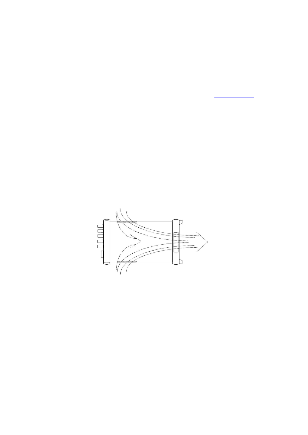
○OXXOTM Series “K”Model power supply is cooled by internal fan. Care must be taken to allow
unrestricted air space at the front and the rear of the unit for proper cooling of power supply. The air
intake is at the side panel ventilation inlets and exhaust is at the rear panel.
[Air Flow of OXXOTM Series “K”Model Power Supply]
○When mounting on equipment rack remove the front and rear bumpers and mount with caution.
Do not obstruct the air exhaust at the rear panel of the unit.
○Please operate this power supply in an environment with no humidity and vibrations.
1-5. Cleaning
○To prolong the life of OXXOTM Series “K”Model power supply periodic cleaning is necessary.
○To clean, disconnect the unit from the AC supply and allow 60 seconds for discharging internal voltage.
○Exterior panels should be cleaned with a mild solution of non-alcoholic detergent and water applied
onto a soft cloth.
○Internal cleaning should be done by removing the cover and blowing away the dust in the heat sink
and the cooling fan. Use low pressure compressed air to blow dust from the unit. Using sharp
metal objects to clean the dust is not recommended due to possibility of causing damage to the unit.
1. Product Information.

- 6 -
1-6. AC Source Requirement
OXXOTM Series “K”Model power supply is designed to operate from a nominal AC 220V/47~63Hz single
phase. If the unit is used in other countries with different voltage and frequency rating than the
specifications on the rear panel of the unit, then the built-in input source circuitry must be modified. In
this case, contact VuPOWER(www.vupower.com) for support
○Changing AC Source Requirement
1. Remove the cover, then locate the “AC Source Alteration Circuit Board”(see diagram below), and
remove it from the slot.
2. Find the correct AC source and insert it back into the slot in the direction of the arrow indicated in
front of selected AC source rating
Example of chainging AC Source Alteration Circuit Board
[ AC Source Alteration Circuit Board ]
○Replacing the Fuse
Unplug the power cord then remove the fuse holder located above the AC cord socket. Replace with
fuse with capacity of ~250V 6.3A
Replacing the Fuse
. [ Replacing the Fuse ]
Warning
Make sure to unplug the power cord prior to changing the AC Source Alteration
Circuit Board or the fuse.
1. Product Information.

- 7 -
2. Product Configuration & Description
2-1. Front Panel
[ Dual Output Model Front Panel Configuration ]
[ Single Output Model Front Panel Configuration ]
①Recall: recalls and executes stored values / also used in
operation recovery
⑧Null (*single output models)
Track: channel link-on / off (*dual output models)
②Setup: Setup Menu
⑨Output On/Off: DC output On / Off
③P1: P1 channel selection
⑩V / I: selection between voltage / current
④Null (*single output models)
P2: P2 channel selection (*dual output models)
⑪Arrow Keys < & >: moves cursor
⑤Store: saves current operation
⑫Jog Shuttle Knob: fine value adjustment
⑥Error: used to check error message / also used to cancel
Setup Menu
⑬Power: switches unit On / Off
⑦Lock: lock-in / lock-out for front panel control keys
⑭Display Panel: indicates output value and operation
status
2. Product Configuration & Description

- 8 -
2-2. Rear Panel
[ Dual Output Model Rear Panel Configuration ]
[ Single Output Model Rear Panel Configuration ]
①AC Power Cord Socket and Fuse
Holder
②GPIB Connector Port
③RS-232C Connector Port
④DC Colling Fan Outlet
⑤Rear Panel Output Ports
2. Product Configuration and Description

- 9 -
2-3. Display Panel
①Dual Output Model ②Single Output Model
[ Display Indicators Per Output Status ]
CC:
Output (P1 or P2) is operating in Constant Current (CC) mode
CV:
Output (P1 or P2) is operating in Constant Voltage (CV) mode
OVP:
Output (P1 or P2) is operating in Over Voltage Protection (OVP) mode
OCP:
Output (P1 or P2) is operating in Over Current Protection (OCP) mode
GPIB / RS-232:
Indicating the operation of GPIB / RS-232 remote interface
Error:
Indicate power supply error
Track:
P1 and P2 linked mode
Lock (Icon):
Indiates front panel control keys locked or unlocked.
2-4. Output Terminal Connection Guide
○Single Output
○Dual Output
[ Direct Connection ] [ Parrallel Connection ]
2. Product Configuration and Description

- 10 -
○ Remote Sensing Connection Guide
[ Remote Sensing Terminal Connection Diagram ]
If the load is distant from the power supply, Sensing Terminal and Output Terminal
connection (Short Bar) should be removed and the connection should be made as
diagram above. This modification eliminates voltage error due to the lengthy output
cables.
Remote Voltage Sensing is available on all front and rear output ports for single output
models. For the dual output models, remote voltage sensing is available by rear
output ports only (use front/rear knob). If the front output ports are used, then the rear
output connections should be removed and vice versa for rear output ports as well.
○ Rear Output Terminal Connection Guide
If the rear outputs are used make sure to remove the front connections (Short Bar) then
connect to Sensing Terminal.
For dual output models, use the ‘Front/Rear Selection Switch’to select rear output (The
status of the switch should be indicated on the display panel.
[ Rear Output Terminal Connection Diagram ]
2. Product Configuration and Description

- 11 -
2-5. Front Panel Key Functions
○ Function Key
Function Key
To recall stored values.
To setup new configuration.
To select P1 output port.
To select P2 output port.
To store output status / from Setup Menu, to execute or save.
In case of an error, it will show error code.
Please refer to “Error Code”for description of error codes.
From Setup Menu, “ERROR”can be used as Cancel.
To enable/disable lock on function keys on the front panel.
When lock is enabled, lock icon will appear on the display panel.
To disable lock, push “LOCK”button again and an unlocked icon will appear on the
display panel. During lock enabled operation, “Output On/Off”button will function
only once to allow sudden stop of output.
To obtain equal output voltage from both P1 and P2.
Both output terminals P1 and P2 can be linked to operate as one.
When enabled, “Track”will appear on the display panel.
To disable, pushc “TRACK”button again and “Track”will disappear from the display
panel.
2. Product Configuration and Description

- 12 -
○ Control Key
Control Key Diagram
Used to immediately stop output voltage (example: to connect new DUT
(Device Under Test)). If pushed again, it will continue to output voltage.
Used to change cursor location to voltage or current.
Used to increase or decrease value during voltage or current selection.
Jog Shuttle is used to increase or decrease value of selected cursor.
2. Product Configuration & Description

- 13 -
3. Features
3-1. Store
Output values can be stored to be recalled for future use.
Each output port, P1 or P2 can store up to 10 values. When an output terminal is saved,
only the voltage and current values are saved but not the status of the setup.
No.
Key Operation
Display Panel
Description
1
P1 06.000V 1.200A
P1 06.000V 1.000A
Set-Limit: 06.000V 2.000A
Select the output port to use.
To change the cursor location, use
the arrows. To change the value of
selected cursor. The maximum
value is as indicated under Set-Limit.
2
Store 01
06.000V 2.000A
This is an example of storing value
06.000V 2.000A in memory 01.
When “STORE”button is pressed,
the value and the # of memory
location (01~10) will appear.
3
01 ~ 10
P1 06.000V 1.000A
Use the Jog Shuttle to select memory
location to save the values to.
Press “STORE”button again to save.
This feature allows each output port
P1 or P2 to save up to 10 values.
3-2. Recall
This feature allows saved values to be recalled to change current output value to a different
output value.
No.
Key Operation
Display Panel
Description
1
P1 or P2
Recall 01
06.000V 1.000A
Select the output port to use.
Press “RECALL”button
2
01 ~ 10, or
Pattern output
P1 06.000V 1.000A
Use the Jog Shuttle to select the
memory location (01~10) and check the
saved value.
Press “RECALL”button again to recall
and use the saved output value.
3. Features

- 14 -
3-3. Error
During operation if an error occurs, unit will alert the operator by sounding a beep and
indiacating “Error”on the display panel.
When “ERROR”button is pressed, it will indicate error message for approximately 2
seconds. During this time, each push of the “ERROR”button will display previous error
messages in the order of occurrence. Verified error messages will be erased. If all error
messages are erased and the unit is operating normally it will indicate “NO ERROR”in the
display panel
3-4. Setup
Press “SETUP”
Use arrows or jog shuttle to select:
SET-Limit
SET-OVP
SET-OCP
SET-Comm
SET-Pattern
SET-Display
SET-Power Fail
SET-Password
SET-Knob beep
SET-Cal-Voltage
SET-Cal-Current
SET-Cal-V Recover
SET-Cal-C Recover
Above settings can be changed by pressing .
During setup user decides to cancel the setting, press .
While the output is turned off, (ex. Output Off) user cannot:
SET-Cal-Voltage
SET-Cal-Current
SET-Cal-V Recover
SET-Cal-C Recover
Above settings are not in the Setup Menu and the values cannot be changed while the
output is turned off.
3. Feature

- 15 -
3-5. Limit Alarm
This feature alerts the user when the power supply reached the current limit set by the user. When the
unit exceeds the limit it will automatically change the mode from ‘CV’to ‘CC’, or ‘CC’to ‘CV’depending
on the mode the unit was operating in, and simultaneousely sound an alarm and alert the user of the
status of the operation.
○Setting the Limit
This feature can set the limit of voltage or current to interchange operation mode between CV (Constant
Voltage) and CC (Constant Current). If the user selects CV mode operation, the voltage minimum
value should be set to zero and the maximum ccurrent value should be at its maximum. In this setup,
when the operating current output reaches the limit set by the user in CV mode, its present CV mode will
automatically change to CC mode to protect any damage to the power supply. If the user selects CC
mode operation, the current minimum value should be set to zero and the maximum voltage value
should be at its maximum. In this setup, when the operating votage output reaches the lmit set by the
user in CC mode, its present CC mode will automatically change to CV mode to protect any damage to
the power supply.
No.
Key Operation
Display Panel
Description
1
P1 or P2
** OUTPUT OFF **
SET-Limit
Select the output port to use..
Turn off output by pressing “OUTPUT
ON / OFF”button.
Press “SETUP”button.
2
SET-Limit
P1 00.000V 5.000A
SET-Limit
P1 00.000V 5.000A
In SETUP-Limit, press “SETUP”to
change the value.
“V/I”button is used to change the cursor
between “V”and “I”.
3
SET-Limit
P1 00.000V 5.000A
** OUTPUT OFF **
P1 00.000V 0.000A
Use the arrows to change the location of
the cursor and use the jog shuttle to set
the value.
Press “P1”or “P2”or “ERROR”button
tosave the value and exit the setting.
The display panel will now indicate
“OUOTPUT OFF”.
Press “OUTPUT ON / OFF”button to
continue the operation.
3. Feature

- 16 -
3-6. Over Voltage Protection (OVP)
This feature turns-off the output voltage when the voltage exceeds the OVP (Over Voltage
Protection) value set by the user, and protects DUT. Over Voltage Protection operates
normally within the value range specified in the “Specifications”section of this manual.
[ IMPORTANT ]
OVP should be set to “OVP OFF" during unit calibration.
○OVP Settings
No.
Key Operation
Display Panel
Description
1
P1 or P2
** OUTPUT OFF **
SET-Limit
SET-OVP
Select the output port to use.
Turn off output by pressing “OUTPUT
ON / OFF” button (recommended).
Press “SETUP” button.
Use the arrows or jog shuttle to select
“SET-OVP”.
2
SET-OVP
OVP ON / OFF
**OUTPUT OFF **
(If “OVP OFF”is selected)
**OVP ON**
(if “OVP ON”is selected)
SET-OVP
Level - 00.000V
Press “SETUP”button again.
Use the jog shuttle to select ON or OFF
Press “STORE”button to save the set
value. If “OVP OFF” is selected, it will
turn off OVP and exit Setup.
If “OVP ON”is selected, user can set the
OVP Level.
3
SET-OVP
Level - 00.000V
** OUTPUT OFF **
OVP
P1 00.000V 0.000A
OVP
Use the arrows to change the location of
the cursor and use the jog shuttle to set
the value.
Press the “STORE”button.
It will save the set value and exit Setup.
If OVP is on it will indicate “OVP” in the
display panel.
Press “OUTPUT ON / OFF”button again
to continue use.
3. Feature

- 17 -
○OVP Occurrence
Upon detection of an Over Voltage condition, the power supply output will shut down.
During this time, “OVP”on the display panel will disappear and “OVP OCCURRED…” will
appear.
○OVP Cancellation
During OVP occurrence, display panel will show “OVP OCCURRED…“and output will
shutdown. If the user wishes to turn on the output, OVP must be cancelled. In order to
cancel OVP please follow the following instructions.
[ IMPORTANT ]
For the protection of DUT, remove the terminal connections during OVP cancellation.
No.
Key Operation
Display Panel
Description
1
OVP OCCURRED…
Indicates OVP occurrence.
2
SET-Limit
SET-Limit
P1 10.000V 5.000A
SET-Limit
P1 09.000V 5.000A
Press the “SETUP”button.
Press the “SETUP”button again and
select “SETUP-LIMIT”.
Move the cursor to voltage.
Use the arrows to change the location of
the cursor and use the jog shuttle to set
the value. Limit value must be 1V less
than OVP set voltage (ex. If OVP limit
was originally set to 10V then the new
limit should be set at 9V or less,
otherwise it will remain at OVP
occurrence status).
3
OVP CLEAR…
(2 seconds later)
** OUTPUT OFF **
OVP
P1 00.000V 0.000A
OVP
Set the new limit and press the
applicable PORT or “ERROR”button to
save and exit the setup.
Now, OVP will cancel and “OVP
CLEAR…” will appear on the display
panel for 2 seconds, then the output will
be turned off.
Display panel will indicate “OVP”.
Press “OUTPUT ON / OFF”button again
to continue use.
3. Features

- 18 -
3-7. Over Current Protection (OCP)
This feature turns off the output when the current exceeds the OCP (Over Current Protection) value set
by the user, and protects Load (DUT) connected to the output terminals. Over Current Protection
operates normally within the value range specified in the “Specifications”section of this manual.
[ IMPORTANT ]
OCP should be set to “OCP OFF" during unit calibration.
○OCP Settings
No.
Key
Operation
Display Panel
Description
1
P1 or P2
** OUTPUT OFF **
SET-Limit
SET-OCP
Select the output port to use.
Turn off output by pressing “OUTPUT
ON / OFF”button (recommended).
Press “SETUP”button.
Use the arrows or jog shuttle to select
“SET-OCP”.
2
SET-OCP
OCP ON / OFF
**OUTPUT OFF **
(If “OCP OFF”is selected)
**OCP ON**
(If “OCP ON”is selected)
SET-OCP
Level - 00.000A
Press “SETUP”button again.
Use the jog shuttle to slect ON or OFF
Press “STORE”button to save the set
value. If “OCP OFF”is selected, it will
turn off OCP and exit Setup.
If “OCP ON”is selected, user can set the
OVP Level.
3
SET-OCP
Level - 00.000V
** OUTPUT OFF **
OCP
P1 00.000V 0.000A
OCP
Use the arrows to change the location of
the cursor and use the jog shuttle to set
the value.
Press the “STORE”button.
It will save the set value and exit Setup.
If OCP is on, it will indicate “OCP”in the
display panel.
Press “OUTPUT ON / OFF”button again
to continue use.
3. Features

- 19 -
○OCP Occurrence
Upon detection of an Over Current condition, the power supply output will shut down.
During this time, “OCP”on the display panel will disappear and “OCP OCCURRED…” will
appear.
○OCP Cancellation
During OCP occurrence, display panel will show “OCP OCCURRED…” and output will
shutdown. If the user wishes to turn on the output, OCP must be cancelled. In order to
cancel OCP please follow the following instructions.
[ IMPORTANT ]
For the protection of DUT, remove the terminal connections during OCP cancellation..
No.
Key Operation
Display Panel
Description
1
OCP OCCURRED…
Indicates OCP occurrence.
2
SET-Limit
SET-Limit
P1 10.000V 5.000A
SET-Limit
P1 10.000V 4.900A
Press the “SETUP”button.
Press the “SETUP”button again and
select “SETUP-LIMIT”.
Move the cursor to voltage.
Use the arrows to change the location of
the cursor and use the jog shuttle to set
the value. Limit value must be 0.1A
less than OCP set current (ex. If OCP
limit was originally set to 5.0A then the
new limit should be set at 4.9A or less,
otherwise it will remain at OCP
occurrence status).
3
OCP CLEAR…
(2 seconds later)
** OUTPUT OFF **
OCP
P1 00.000V 0.000A
OCP
Set the new limit and press the
applicable PORT or “ERROR”button to
save and exit the setup.
Now, OCP will cancel and “OCP
CLEAR…” will appear on the display
panel for 2 seconds, then the output will
be turned off.
Display panel will indicate “OCP”.
Press “OUTPUT ON/OFF”button again
to continue use.
3. Features

- 20 -
3-8. Pattern Output
The terms used in this feature are defined as follows:
1. Pattern Output: continuous output of user set voltage over user set period of time.
2. Steps: duration of continuous user set voltage output (minimum 1 second to maximum 5
hours). The first output voltage is called, “Step 1”. When the user programs patters
from the front panel, total of 10 “Steps”can be set. If additional “Steps”are needed, use
remote connection feature.
3. Repeats: determine the number of repeated output of total “Steps”programmed by the
user. For example, if there are five “Steps”set by the user and the user wants it to be
repeated six times, then the unit will continuously output until it completes the cycle of
Step 1 thru Step 5, six times.
[ IMPORTANT ]
Prior to operating Pattern Output, make sure to check Pattern Output Condition
Settings. Pattern Output can only change voltage limit values. Therefore, voltage
limit values should be set to meet specifications of DUT (Device Under Test).
○Pattern Output Conditon Settings
To program Pattern Output number of Steps (1~10) and the number of times required to
repeat (maximum of 100 times allowed), voltage of each Steps (1~10), and the duration of
required continuous output are necessary. If there is correction to be made during Pattern
Output programming, press “ERROR”button to go back to the previous step.
No.
Key Operation
Display Panel
Description
1
P1 or P2
** OUTPUT OFF **
SET-LIMIT
SET-PATTERN
Select the port to set Pattern Output
Condtion.
Turn off output by pressing “OUTPUT
ON / OFF”button (recommended).
Press “SETUP”button.
Use the arrows or jog shuttle to select
“SET-PATTERN”.
Press “SETUP”button again.
2
SET-PATTERN
Step –01 to 10
SET-PATTERN
Step –01 to 10
This is where the user decides the
number of output “Steps”.
Use the arrows to change the location of
the cursor and use the jog shuttle to set
the value.
3. Features
This manual suits for next models
10
Table of contents
Popular Power Supply manuals by other brands

Branson
Branson DCX A Series Original instructions

Extron electronics
Extron electronics VNM 12 PS installation guide

Thermal Dynamics
Thermal Dynamics MERLIN 6000 Service manual

Black & Decker
Black & Decker 1VPX 90521888 instruction manual

Peavey
Peavey PS 2C Specifications

Ametek
Ametek Sorensen Operation manual