STATRON 3231.10 User manual
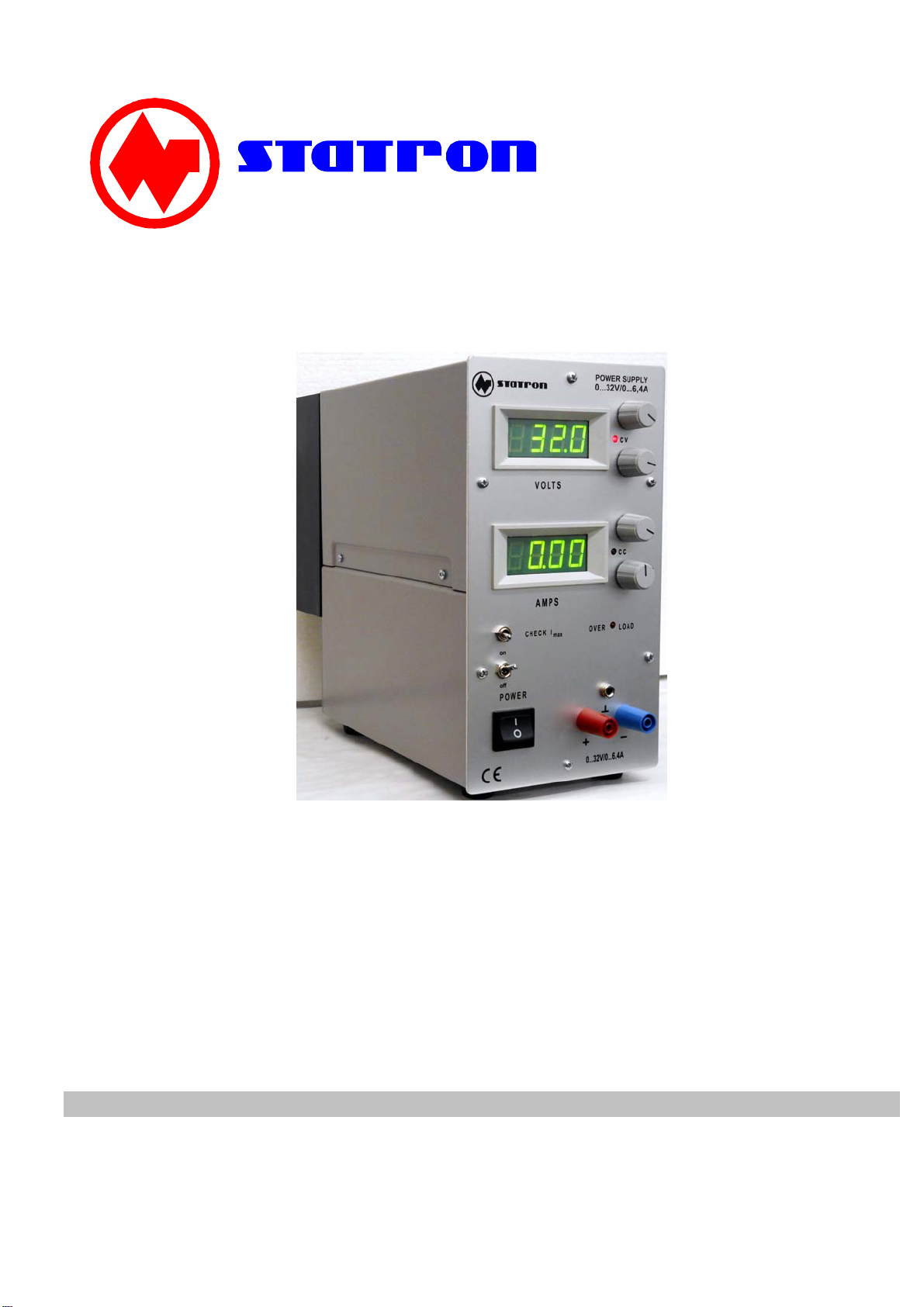
regulated power supply type 3231.10
The correct use of this voltage regulator is:
the connection and use of loads with a d.c. voltage between 0 and 32 VDC and current max.6,4A.
Attention!
Do read this manual carefully. This warranty does not apply to fuses, disposable batteries or to any
product that has been misused, altered, neglected or damaged by accident or abnormal conditions of
operation or handling. We will not be liable for any indirect, special, incidental, or consequential
damages.
Table of contents
1. Introduction
2. Safety instructions (connection to line / changing of fuses)
3. Control Elements, Display and Connections
4. Operation and application
5. Specifications
Gerätetechnik GmbH

2
1. Introduction
This d.c. voltage regulator is an infinitely variable voltage source with high stability and low internal
resistance. The regulator can operate both as voltage stabilizer and as current stabilizer in dependence
on the load resistance. The manifold characteristics of the d.c. voltage regulator secure its application
everywhere where constant d.c. voltages with low internal resistance or constant direct current with high
internal resistance of the supply source are needed in research and development, production and
testing.
The output voltage and current will be shown via an analogue or digital instrument, dependent of the
Type. The current pre-set can be shown, even if the regulator is not in constant current mode, by
pressing the I-max button.
2. safety instructions
2.1 EC Declaration of Conformity
This power supply meets the intent of Directive 89/366/EEC for Electromagnetic Compatibility.
Compliance was demonstrated to the following specifications as listed in the Official Journal of the
European Communities:
EN 50081-1 Emissions:
EN 55022 Class B Radiated and Conducted Emissions
EN 60555-2 AC Power Line Harmonic Emissions
EN 50082-1 Immunity:
2.2 The power supply has been designed and tested in accordance with Safety Class I requirement of
IEC Publication 348, Safety Requirements for Electronic Measuring Apparatus.
2.3 This power supply is for only use on 230V/50Hz line voltage. Make sure that the line has this
voltage.
2.4 Do not leave the power supply in uncontrolled conditions.
2.5 Plug off the line cable before you opening of the case. Changing fuses and modifying line cables to
local power must be done by qualified service personnel who are aware of the hazards involved. If
you suspect the supply has failed, review this manual to make sure you are operating it correctly. If
the supply still fails to operate properly, pack it securely (in its original container if available) and
forward it, postage paid, to the Address listened at the end of this Manual. Note that a repair must
be paid if the warranty time is over or if the supply shows signs of a unproper use. We assume NO
responsibility for damage in transit. Customer shall be responsible for paying all shipping charges,
duties, taxes, and any other charges for product returned to us.
2.6 Wait to use the supply until the supply has reached proper environmental conditions.
2.7 You must follow the appropriate safety guidelines for work with electricity.
2.8 This product is not authorized for use on humans or animals.
2.9 If two or more output terminals are connected in series hazardous voltages ( > 42V DC) will exist on
the outer terminals.
2.10 Do not cover the ventilation holes at the bottom and at the top. The unit can be operated on a
horizontal surface in a flat position. You must assure that there is at least two inch's clearance
around the unit. Some hot spots on the case can reach 90 °C.
3
2.11 Do not physically abuse the unit. Dropping it off a workbench or bouncing it around the trunk of a
car or the back of a truck may cause damage. Protect the unit while transporting it and use it where
it cannot be accidentally hit, kicked, or dropped.
2.12 If the unit fails higher voltages then set up can lie on the sockets. Switch off the unit in this case.
Remember that we can not be make responsible for damages caused by failing of the unit.
2.13 Do not use the unit if:
- there are visible damages,
- the unit do not work,
and
- after longer storing under bad conditions
or
- heavy transport hit the unit.
2.14 Electronic circuits do not mix well with water, chemicals, dust, or grid. Avoid exposing your
instrument to these or other contaminants. The case is not water- or air-tight. Do not place liquid
containers on or near the unit where they can be splled into it.
2.15 A series connection of several units is allowed only to a overall voltages of 1000V DC.
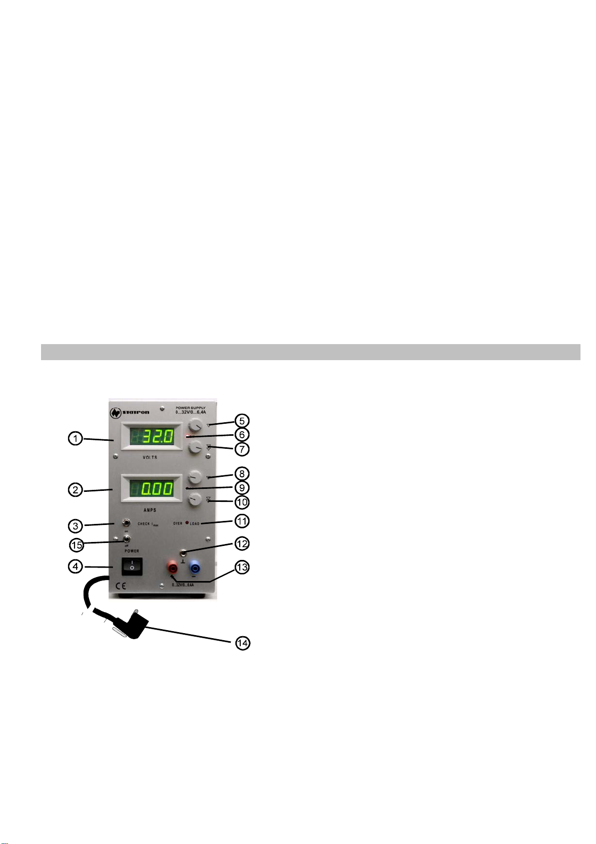
3. Control elements
1 Voltage Display
2 Current Display
3 Switch to display the max.
current.
4 Powerswitch
5 knob for voltage control
coarse
6 LED is lit when in constant
voltage mode
7 knob for voltage control
fine
8 knob for current control
coarse
9 LED is lit when in constant
current mode
10 knob for current control
fine
11 LED is lit when overloaded
temperature is too high
12 Ground
13 Output terminal
red = + black = -
14 power cable with power
plug
15 Switchfor output clamps

4
4. Operation and application
a) Connection
Make sure that you are using a 230V/50-60Hz line voltage. Then plug in the power plug, turn the control
knobs right (0V / 0A position) and switch the unit on. Chose the voltage your need. You can set-up the
current by switching the Imax switch. When outputcurrent reach the preseted value, mode will change
into constant current.
Caution!
Parts of the unit ( heatsinks ) will be hot when maximum current is used. The unit has a build in
overtemperatur protection, which will switch the unit temporally off when 90°C are reached. After a period
of cooling the unit automatically switches on.
Caution!
Do not cover the ventilation holes. You must ensure that there are at least two inch's clearance around
the unit. Take care that the cables of your load are tight connected with the unit. Even low voltage can
cause electric sparkles that can harm the terminal and your load.
b) setting up the voltage (with no load)
Turn the coarse knob for the current a little clock wise to ensure that the current regulator is not set to
zero. The LED for constant current is off and the LED for constant voltage is on then. Now you can set up
your voltage.
c) setting up the current
Push the switch Imax. The current display now shows the value for the maximum current you can use.
Set up the current and release the switch. The unit will now change in to constant current mode if the
current through your load is reaching se value you set up.
caution!
Pay attention on the safety instructions in chapter 2 of the manual..
5 specifications
common to the serie
ac line voltage : 230 VAC +6/-10%
ac line frequency range : 50 Hz
protection class (IEC 348) : I
Common Mode Voltage : 3750 Veff from line to terminals
Common Mode Voltage : 500Veff from terminals to ground
Warmup time : 15 min
Environmental
Operating Temperature : + 0 °C bis +35 °C
Relative Humidity (non-condensing) : max. 85 % by 30 °C
Air pressure : 800 bis 1333 hPa
This manual suits for next models
1
Other STATRON Power Supply manuals


