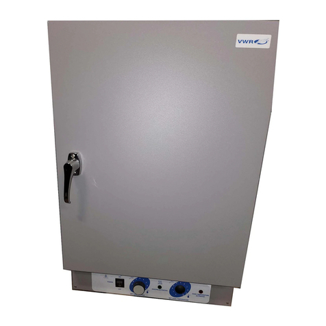
VWR International 89508-424 Operating instructions

User Manual
VWR®Collection Model 89508-424
Small Vacuum Oven
Operating and Maintenance Manual 7006290 • Rev. 0

VWR Collection
MANUAL NUMBER 7006290
0 -- 10/7/13 Original ccs
REV ECR/ECN DATE DESCRIPTION By
Preface
Small Vacuum Oven i

VWR Collectionii Small Vacuum Oven
Preface
Important Read this instruction manual. Failure to read, understand and follow the instructions in this manual
may result in damage to the unit, injury to operating personnel, and poor equipment performance. s
Caution All internal adjustments and maintenance must be performed by qualified service personnel. s
Material in this manual is for information purposes only. The contents and the product it describes are subject
to change without notice. VWR International makes no representations or warranties with respect to this
manual. In no event shall VWR be held liable for any damages, direct or incidental, arising out of or related to
the use of this manual.
©2013 VWR International, LLC. All rights reserved.

VWR Collection Small Vacuum Oven iii
Preface
Important operating and/or maintenance instructions. Read the accompanying text carefully.
Potential electrical hazards. Only qualified persons should perform procedures associated with this
symbol.
Equipment being maintained or serviced must be turned off and locked off to prevent possible injury.
Hot surface(s) present which may cause burns to unprotected skin, or to materials which may be
damaged by elevated temperatures.
Marking of electrical and electronic equipment, which applies to electrical and electronic equipment
falling under the Directive 2002/96/EC (WEEE) and the equipment that has been put on the market
after 13 August 2005.
This product is required to comply with the European Union’s Waste Electrical & Electronic
Equipment (WEEE) Directive 2002/96/EC. It is marked with the WEEE symbol. VWR International
has contracted with one or more recycling/disposal companies in each EU Member State European
Country, and this product should be disposed of or recycled through them. Further information on
VWR’s compliance with this directive, the recyclers in your country and information on VWR
products will be available at www.vwrsp.com.
4Always use the proper protective equipment (clothing, gloves, goggles, etc.)
4Always dissipate extreme cold or heat and wear protective clothing.
4Always follow good hygiene practices.
4Each individual is responsible for his or her own safety.


Small Vacuum Oven ivThermo Scientific
Table of Contents
Description . . . . . . . . . . . . . . . . . . . . . . . . . . . . . . . . . . . . . . . . . . . . . . . . . .1-1
Safety . . . . . . . . . . . . . . . . . . . . . . . . . . . . . . . . . . . . . . . . . . . . . . . . . . . . . . .2-1
Specifications . . . . . . . . . . . . . . . . . . . . . . . . . . . . . . . . . . . . . . . . . . . . . . .3-1
Unpacking and Installation . . . . . . . . . . . . . . . . . . . . . . . . . . . . . . . . . . . .4-1
Location . . . . . . . . . . . . . . . . . . . . . . . . . . . . . . . . . . . . . . . . . . . . . . .4-1
Vacuum Pump Connections . . . . . . . . . . . . . . . . . . . . . . . . . . . . . . . .4-1
Electrical Power . . . . . . . . . . . . . . . . . . . . . . . . . . . . . . . . . . . . . . . . .4-2
Thermometer Placement . . . . . . . . . . . . . . . . . . . . . . . . . . . . . . . . . .4-2
Shelving . . . . . . . . . . . . . . . . . . . . . . . . . . . . . . . . . . . . . . . . . . . . . . .4-2
Features . . . . . . . . . . . . . . . . . . . . . . . . . . . . . . . . . . . . . . . . . . . . . . . . . . . . .5-1
Control Panel . . . . . . . . . . . . . . . . . . . . . . . . . . . . . . . . . . . . . . . . . . .5-1
Topside of Oven . . . . . . . . . . . . . . . . . . . . . . . . . . . . . . . . . . . . . . . . .5-2
Operation . . . . . . . . . . . . . . . . . . . . . . . . . . . . . . . . . . . . . . . . . . . . . . . . . . . .6-1
Temperature Control . . . . . . . . . . . . . . . . . . . . . . . . . . . . . . . . . . . . .6-1
Purging the Chamber with Inert Gas . . . . . . . . . . . . . . . . . . . . . . . . .6-2
Vacuum Control . . . . . . . . . . . . . . . . . . . . . . . . . . . . . . . . . . . . . . . .6-2
Loading the Oven . . . . . . . . . . . . . . . . . . . . . . . . . . . . . . . . . . . . . . .6-2
Maintenance . . . . . . . . . . . . . . . . . . . . . . . . . . . . . . . . . . . . . . . . . . . . . . . .7-1
Routine Cleaning . . . . . . . . . . . . . . . . . . . . . . . . . . . . . . . . . . . . . . . .7-1
Door Gasket Lubrication . . . . . . . . . . . . . . . . . . . . . . . . . . . . . . . . . .7-1
Heater Replacement . . . . . . . . . . . . . . . . . . . . . . . . . . . . . . . . . . . . . .7-2
Fusible Link Replacement . . . . . . . . . . . . . . . . . . . . . . . . . . . . . . . . .7-2
Section 1
Section 2
Section 3
Section 4
Section 5
Section 6
Section 7

Small Vacuum Oven 1-1VWR Collection
Section 1 Description
The vacuum ovens covered in this manual are designed for drying
applications under controlled conditions at either normal atmosphere or a
vacuum of up to 30-inches of mercury. The ovens have use in desiccating,
vacuum embedding, plating and electronic component processing
applications. Nitrogen, CO2 and other noncorrosive, non-flammable gases
can be used in the oven.
Control panels include a lighted power switch, temperature control dial
and heat-indicating light.
The vacuum control and release valves are on top of the oven. Vacuum
levels are precisely controlled between 0 and 30-inches of mercury, with
the door gasket assuring a tight seal at all vacuum levels. The inner
window is high-strength tempered glass and the outer door incorporates a
safety shield of shatter-proof polycarbonate.
Radiant, warm-wall heat surrounds the chamber for uniform heating. Two
solid aluminum shelves provide heat conduction to the load. Three inches
of glass-wool insulation assure optimum temperature control.


Small Vacuum Oven 2-1VWR Collection
Section 2 Safety
Your VWR Collection Vacuum Oven has been designed with function,
reliability, and safety in mind. It is your responsibility to install it in
conformance with local electrical codes. It is most important that the user
follow installation instructions exactly as written. Failure to do so is likely
to lead to improper operation, erroneous calibrations and possible damage
to the equipment. Use in the manner specified by the manufacturer. If not,
the protection provided by the equipment may be impaired. Do not
attempt operation without this information.


Small Vacuum Oven 3-1VWR Collection
Section 3 Specifications
Electrical Requirements
120VAC, 50/60 Hz, 5.0 Amps, 600 Watts
Temperature Range
Slightly above ambient to 220°C
Thermometer Type
Bimetallic, dial type; range from 0°C to 300°C in 5°C increments
Dimensions
Interior: 8" W x 12" D x 8" H (20 x 30 x 20 cm)
Exterior: 17" W x 16" D x 17-3/8" H (43 x 41 x 44 cm)
Volume
0.44 cubic feet (12.5 liters)
Net Weight
57 lbs. (26 kg)
Environmental Conditions
Pollution Degree 2
Installation Category II
Altitude: 2000 Meters MSL (Mean Sea Level)
Humidity: 70% maximum, non-condensing
Electrical Supply: 120VAC
Voltage Tolerance: ±10% of normal rated line
Temperature: 15°C to 40°C
Indoor use only


Small Vacuum Oven 4-1VWR Collection
Section 4 Unpacking and Installation
The shipping carton should be inspected upon delivery. When received,
carefully examine for any shipping damage before unpacking. If damage is
discovered, the delivering carrier should both specify and sign for the
damage on your copy of the delivery receipt.
Open the carton carefully making certain that all parts are accounted for
before packaging materials are discarded. After unpacking, if damage is
found promptly report it to the carrier and request a damage inspection
promptly.
Important Failure to request an inspection of damage within a few days
after receipt of shipment absolves the carrier from any liability for damage.
You must call for a damage inspection promptly.
Place the oven near an electrical outlet meeting the requirements stated on
the name plate and in a location away from drafts and free from wide
temperature variations.
Allow enough space around the oven for the free circulation of air. Heat
escaping through the oven walls and top must be carried off by normal
convection. Do not place oven near an open window, radiator or ventilator.
It must not be placed on a combustible surface or be stacked directly on
top or under another oven. If a vacuum pump or insert gas source will be
used, allow room for the equipment.
To operate the unit as a vacuum oven, connect 1/4-inch ID tubing to valve
on either side. Connect the other end of the tubing to your vacuum pump.
Location
Vacuum Pump
Connections

4-2 Small Vacuum Oven VWR Collection
Section 4
Unpacking and Installation
Shelving Install the two shelves. While the door is open, apply a high-quality
vacuum grease to the door gasket.
Place the thermometer so that the sensing element is in direct contact with
the top shelf. The dial should be easily visible through the glass door.
Note It is important to place the sensing element of the thermometer in
direct contact with the shelf or sample that is being heated, in order to
obtain a precise reading of the temperature under vacuum conditions.
Make sure that the dial is clearly visible through the glass door. s
The unit is supplied with a 3-wire line cord. It should be plugged into an
outlet supplying the correct voltage for the unit and designed for 3-prong
plugs.
For an outlet designed to accept 2-prong (ungrounded) plugs, the best
recommendation is to have a qualified electrician replace it with a new
grounded outlet.
If a plug must be installed, use only the 3-prong grounded type, rated for
the unit load requirements and matching the power outlet. Make sure the
green ground wire is secured to the plug ground post.
Turn the power switch to the OFF position and insert plug into an outlet
meeting the electrical requirements of the unitʼs nameplate.
Note Disconnect unit from power source when not in use. s
Caution Disconnect plug from electrical outlet before attempting any
maintenance or repair on this unit. s
Thermometer
Placement
Electrical Power

Small Vacuum Oven 5-1VWR Collection
Section 5 Features
1. POWER SWITCH: An illuminated, rocker-type switch controls
electric power to the entire unit. The switch lights when the top half is
depressed and indicates that power is on.
2. TEMPERATURE CONTROL DIAL: This thermostat controls the
temperature of the oven. While the dial scale of 0 to 10 does not
indicate the actual temperature settings and is for REFERENCE
ONLY, it does allow the user to repeat a temperature setting after
experience is gained in its use.
3. HEAT INDICATOR STATUS LAMP: This lamp lights whenever heat
is being applied to the chamber.
Control Panel
Power Switch Temp Control
Dial
Heat Indicator
Status Lamp

5-2 Small Vacuum Oven VWR Collection
Section 5
Features
5. VACUUM PORT: Located on the left side of the top of the chamber,
this is an outlet to the vacuum pump (not supplied). Connect 1/4-inch
ID tubing between this port and your vacuum pump; adjust the pet
cock to control the vacuum draw.
6. VACUUM GAUGE: A large-dial indicator located between the two
topside ports, this gauge is scaled down from 0 to 30-inches of
mercury. It indicates the level of vacuum in the chamber.
7. VACUUM RELEASE PORT: Located on the right side of the top of
the chamber, this is an inlet that allows air into the chamber through
the vacuum release valve, a pet cock near the port. Also used as a purge
inlet (connect 1/4-inch ID tubing from the inert gas source to purge
the chamber).
Topside of Oven
Vacuum Port Vacuum Gauge
Vacuum
Release Port

Section 6 Operation
Caution Do not use in the presence of flammable or combustible materials
or explosive gases. Do not use in the presence of pressurized or sealed
containers - fire or explosion may result, causing death or severe injury. s
Caution Do not heat any substance above a temperature which will cause
it to emit toxic fumes - death or severe injury may result. s
Caution Do not operate the oven at temperatures above the upper limit
(220°C) stated in this manual; doing so will void the warranty. s
Caution When the oven is operating at high temperatures, do not touch
the surfaces of the oven; they become quite warm. s
If it is necessary to set temperature before loading the oven, turn the power
switch ON and note that the power switch is lit. Rotate the thermostat
knob to approximate the desired setting. The heater indicator status lamp
will remain lit until the chamber temperature approaches the thermostat
setting. Wait several heat cycles until the temperature has stabilized.
Check the dial thermometer and rotate the thermostat knob clockwise to
raise the setpoint or counterclockwise to lower it, as required. After oven
temperature has stabilized, check the dial thermometer again and make
further thermostat adjustments until the thermometer consistently shows
the desired operating temperature. Turn the power switch OFF and allow
the oven to cool down, or if a batch is ready for baking, the oven can be
loaded immediately.
Small Vacuum Oven 6-1VWR Collection
Temperature Control

The dial thermometer can be removed and put back after loading, if it is
more convenient. For precise measurement, be sure thermometer sensing
element directly contacts a shelf or sample.
Distribute the load evenly in the chamber, at least 1-inch away from
chamber walls and resting directly on the shelves or best results.
The following are directions for operating the oven in a vacuum mode:
1. Apply a high-quality vacuum grease to the door gasket, load the oven,
and close the door.
2. Close the vacuum release valve (on the topside, right) and open the
vacuum valve (topside left).
3. Turn the vacuum pump on and note the vacuum gauge dial (graduated
in inches of mercury). Just as the gauge needle reaches the desired
setting, close the vacuum control valve completely and turn off pump.
4. If there is greater vacuum than desired in the chamber, open the
vacuum release valve slightly until the correct reading is obtained, then
close it.
5. After a period of several hours, the vacuum level is likely to decrease an
inch or so. Re-establish the original level by repeating Steps 2 and 3.
Some applications call for replacing the vacuum with an inert gas while the
bake continues. Use only noncorrosive, nonflammable gases, such as
nitrogen and CO2 for purging.
1. Connect 1/4-inch ID tubing to the vacuum release port (right side).
Connect the other end of the tubing to the regulator on a gas cylinder
or bottle.
2. Start the gas flowing at no more than 5 psi. Open the vacuum release
valve and observe the vacuum gauge. The vacuum level will fall as the
chamber approaches atmospheric pressure.
3. Turn off the gas when vacuum gauge reads zero. Turn vacuum release
valve to the CLOSED position. Disconnect hose from barbed fitting.
Caution Do not pressurize the oven chamber to a level higher than
atmospheric pressure. When the vacuum gauge reads zero, turn off the gas.
The oven is designed to retain a vacuum, not to withstand any positive
internal pressure. Any positive internal pressure may damage component
parts and/or result in injury. The oven does not require very much gas to
fill the chamber - approximately 0.4 cubic feet. s
6-2 Small Vacuum Oven VWR Collection
Section 6
Operation
Loading the Oven
Vacuum Control
Purging the Chamber
with Inert Gas

Section 7 Maintenance
Caution Make no attempt to service or repair a VWR product under
warranty before consulting your distributor. After the warranty period,
such consultation is still advised, especially when the repair may be
technically sophisticated or difficult.
If assistance is needed beyond what the distributor can provide, please call
the Technical Services department. No merchandise, however should be
returned without prior approval.
Caution Disconnect plug from electrical outlet before attempting any
maintenance or repair of this unit. s
Wash the cabinet with a solution of water and mild soap or detergent to
clean off surface dirt, marks or smudges. Keep the vents clear of dust for
free air circulation. This will add to the service life of components.
Clean up spills inside the chamber as soon as possible to prevent them
from being baked on. When the oven is cool, use hot soapy water and a
soft cloth to clean the #304 stainless steel chamber. Do not use scouring
pads with metallic content, chlorine bleach or halogen-based cleaners.
The aluminum shelf assembly should be washed with a mild soap and
water. Do not use abrasive or halogen-based cleaners. They will damage
the finish. Rinse thoroughly and dry completely.
Wipe interior glass with an ammonia-based glass cleaner and a soft, lint-
free cloth.
Clean exterior safety shield with a solution of mild soap and water using
soft lint-free cloth. Do not use abrasive cleaners or other strong solutions.
They will harm surface of the safety shield and reduce clarity.
Apply a high-quality vacuum grease to the door gasket frequently,
especially before initiating a vacuum, after shutdown, or if the oven is not
expected to be used in the near future.
Small Vacuum Oven 7-1VWR Collection
Routine Cleaning
Door Gasket
Lubrication
Table of contents
Other VWR International Oven manuals

VWR International
VWR International 1310 User manual

VWR International
VWR International 1400E Quick guide

VWR International
VWR International 1410 Quick start guide

VWR International
VWR International 1470 Quick start guide

VWR International
VWR International 1310 User manual

VWR International
VWR International 89508-426 Manual

VWR International
VWR International 1330FM User manual