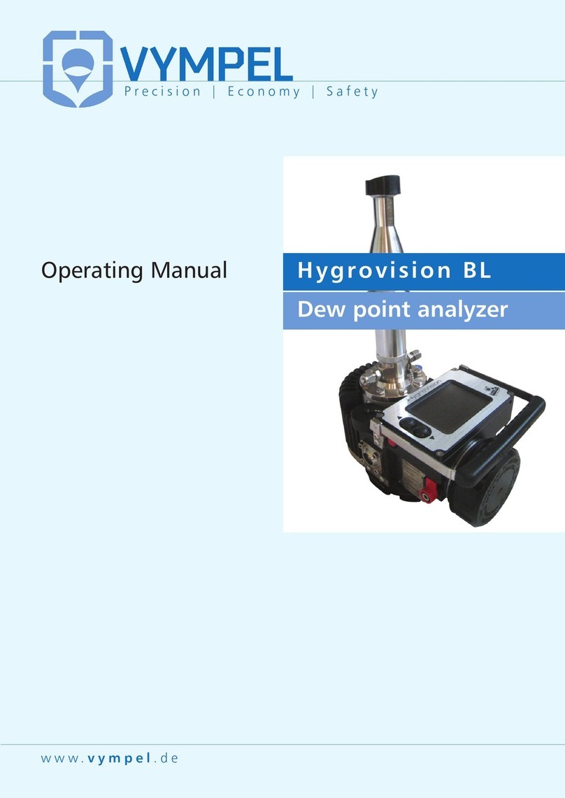
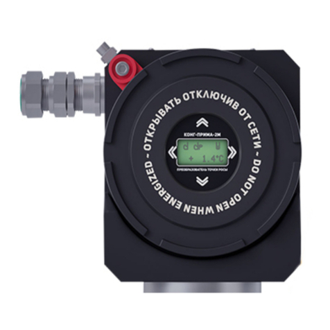
Vympel Hygrovision Mini User manual

www.vympel.de
Hygrovision mini
Dew point analyzer
Operating Manual
Precision | Economy | Safety
Vympel_OperatingManual_EN 04.07.14 09:42 Seite 3

2
Contents
1!Analyzer description.............................................................. 4!
1.1!Purpose and applications.............................................................. 4!
1.2!Technical characteristics............................................................... 5!
1.3!Measurement principle.................................................................. 6!
1.4!Construction.................................................................................. 6!
1.4.1!The Hygrovision mini’s main components and controls ............................8!
1.4.2!Hygrovision mini power supply..................................................................9!
1.4.3!Control and display elements ..................................................................10!
1.4.4!Turning the Hygrovision mini on and off..................................................11!
1.5!Menu of the Hygrovision mini...................................................... 12!
1.5.1!Menu structure ........................................................................................12!
1.5.2!Main menu...............................................................................................13!
1.5.3!“Mirror cleaning” ......................................................................................13!
1.5.4!“Measuring the dew point: Тdp”................................................................14!
1.5.5!“Settings” .................................................................................................15!
1.5.6!Status of the battery charge ....................................................................16!
1.5.7!Program codes ........................................................................................17!
1.6!Accessories and additional equipment ....................................... 18!
1.6.1!Battery charger........................................................................................18!
1.6.2!Sample gas delivery system....................................................................18!
1.6.3!Through-flow control system ...................................................................19!
1.6.4!Particle filter.............................................................................................19!
1.6.5!Filter for the control of heavy hydrocarbons ............................................20!
1.6.6!Sample extraction set..............................................................................20!
1.6.7!Supplemental cooling system..................................................................20!
1.7!Hygrovision mini set.................................................................... 21!
1.8!Explosion safety provisions......................................................... 23!
1.9!Markings ..................................................................................... 24!
1.10!Packaging ................................................................................. 24!
2!Proper operation of the Hygrovision mini............................ 25!
2.1!General requirements .................................................................25!
2.1.1!Unpacking and visual inspection of the device........................................25!
2.1.2!General requirements for the sample extraction site ...............................25!
2.1.3!General safety measures ........................................................................25!
2.2!Connecting the analyzer ............................................................. 26!
2.3!Using the Hygrovision mini ......................................................... 27!
2.3.1!Preparing to take dew point measurements............................................27!
2.3.2!Visual identification of water condensation .............................................28!
2.3.3!Visual identification of hydrocarbon condensation .................................29!
2.3.4!Rough dew point measurement ..............................................................31!
2.3.5!Measuring water and hydrocarbon dew points.......................................33!
2.3.6!Supplemental cooling ..............................................................................37!
2.4!Deinstallation of the Hygrovision mini ........................................ 38!

3
3!Maintenance ........................................................................39!
3.1!Function tests ..............................................................................39!
3.1.1!Check the status of the battery charge ................................................... 39!
3.1.2!Check the condensation mirror............................................................... 40!
3.1.3!Check that the thermoelectric battery – TEB (Peltier element) is
functioning .......................................................................................................... 40!
3.1.4!Check the lighting systems ..................................................................... 40!
3.1.5!Perform a leak test.................................................................................. 41!
3.2!Maintenance procedures .............................................................41!
3.2.1!Servicing the power supply unit IP-01 .................................................... 41!
3.2.2!Cleaning the condensation mirror........................................................... 41!
3.2.3!Checking the efficiency of the thermoelectric battery (TEB).................. 43!
3.2.4!Replacement of the particle filter ............................................................ 44!
3.2.5!Calibrating the Hygrovision mini ............................................................. 44!
3.3!Troubleshooting malfunctions......................................................45!
3.4!Error message codes...................................................................46!
4!Markings ..............................................................................47!
5!Packaging............................................................................47!
6!Storage ................................................................................47!
7!Transportation .....................................................................48!
8!Recycling .............................................................................48!
Anlage А...................................................................................49!
Factory settings ...................................................................................49!
Appendix B ...............................................................................50!
Sample extraction system....................................................................50!
Appendix C...............................................................................51!
Membrane Filter (KRAY6.457.022) .....................................................51!
Function.............................................................................................................. 51!
Description ......................................................................................................... 51!
Membrane .......................................................................................................... 51!
Technical Data ................................................................................................... 52!
Recommended installation and usage ............................................................... 52!
Anlage D...................................................................................54!
Examples of the appearance of water and hydrocarbon
condensation .......................................................................................54!
Appendix E ...............................................................................57!
Appendix F ...............................................................................58!

4
1 Analyzer description
1.1 Purpose and applications
The Hygrovision mini is a compact analyzer designed to measure the dew points of wa-
ter and hydrocarbons.
This portable hygrometer (hereafter also analyzer) is an instrument that is designed to
directly measure dew point temperatures by means of a temperature-controlled mirror.
Hygrovision mini areas of application:
⇒Spot check measurements in the field
⇒Check the operational performance of permanently installed Hygrometers
⇒Confirm previous measurement results
⇒Regularly measure water and hydrocarbon dew points directly in locations that are
not equipped with automatic through-flow hygrometers or where no such instruments
can be permanently installed.
⇒Monitor various products as well as working and manufacturing processes (for exam-
ple, drying and vacuuming of facilities, systems, damp presses, steamers, regenera-
tors, evacuators, etc.)
Hygrovision analyzers can be used in a variety of sectors including the gas, oil and chemical
industries, metallurgy, power generation, instrument engineering and many other fields, in
order to provide quality control of production processes where water and hydrocarbon dew
point values are of relevance.
The analyzer is certified “explosion-proof” as defined by EN 60079-0:2009 and it has a
“flameproof enclosure” in accordance with EN 60079-1:2007. The Hygrovision mini has
an “intrinsically safe power circuit” as per EN 60079-11:2007 and is labelled II 2G
Exd [ib] IIB+H2 Т5.The analyzer can be deployed in designated explosion risk areas of
indoor and outdoor installations in accordance with EN 60079-14:2008 and in other ex-
plosive areas where the use of electrical equipment is controlled by regulation.

5
1.2 Technical characteristics
Table 1
Water
≥-50 °C (Thousing)
Measurement range:
Hydrocarbons
≥-50 °C (Thousing)
Water
±1 °C
Absolute error
Hydrocarbons
±1 °C
Recommended volume of
sample gas stream
0.3 –0.5 N L/min
9 –12.6 V
Power supply: voltage
current / power requirement
4 Ah / 15 W
Battery charge life
Min. 12 h
Operating temperature range
-10 °C –+50 °С
Ambient humidity
Max. 98% at < + 35°C
Operating pressure
< 100 bar
Sample gas temperature
-20 °C –+50 °C
Enclosure protection per
IEC 60529
IP 54
Dimensions (without Microscope)
253x120x110 mm
Weight (without replacement
parts and accessories)
4 kg
Suitable installation
In closed rooms or in open areas
(explosion hazard zones)
Connection to the sample
gas delivery piping
Swagelok connector for pipes (tubes) with
an outer diameter of 6 mm
Service life:
-Analyzer*
10 years
-Battery
300 charging cycles
max. of two years
* -with regular maintenance and replacement of parts subject to wear

6
1.3 Measurement principle
The Hygrovision mini analyzer registers the dew point of water or hydrocarbons in a
gaseous mixture according to the principle of direct measurement, utilizing a mirror that
can be heated and cooled.
The measurement process involves monitoring the surface of the mirror and noting the tem-
perature at the moment condensation forms on its surface.
In addition, the observation process is enhanced by the availability of two different light-
ing systems for illuminating the dielectric condensation mirror.
During the measurement cycle the reflectivity of the mirror is monitored. When the dew
point is reached reflectivity decreases as a condensation film forms. The temperature
(T) at which this happens is the dew point.
The analyzer is equipped with an achromatic 40-power microscope for observing the
surface condition of the mirror. In addition, there are two options for illuminating the
mirror: vertical and side lighting.
•Vertical lighting can be used for the visual registration of the water and hydro-
carbon dew points.
•Side lighting is used specifically for the visual registration (confirmation) of the
dew point of water only.
The low angle of this illumination increases the optical intensity created by the scatter-
ing of light rays striking water condensation. This effect makes it possible to register
condensation earlier and with absolute clarity.
The mini is outfitted with a button pad that serves as the control interface. For example, it is
used to manually switch between lighting systems during the measurement process and to
regulate the mirror temperature. The temperature at which a clear condensation film forms
on the mirror’s surface is also fixed using this button keypad.
1.4 Construction
The Hygrovision mini analyzer has an explosion-proof design. For more information
about explosion proofing see point 1.8.
The analyzer consists of a cold body housing, a high-pressure gas delivery system,
and an optical system.
The optical system includes a microscope and two lighting elements: one mounted
perpendicular to the mirror and one at a low angle.
The housing body of the analyzer includes an electronics unit and a measurement
cell. In order to support autarkic operations, the body of the mini includes a battery
compartment designed for the mini’s rechargeable battery.
The measurement cell, the gas delivery system, and the microscope, combined form
the measurement chamber. The measurement chamber is designed to accommodate
a working pressure of 100 bar.

7
The measurement cell includes the temperature-controlled condensation mirror, which
has an integrated thermal sensor, a thermoelectric battery, and a light emitting diode
for providing the side illumination.
The gas delivery system guides the sample gas over the temperature-controlled mir-
ror in the measurement cell. This system includes a small observation window for
monitoring the condensation process and a particle filter to protect against contamina-
tion.
The microscope is mounted directly onto the gas delivery system. The vertical lighting
system is integrated into the microscope.
The electronics unit is made up of the liquid crystal display, the replaceable power
source (battery), and a four-button control unit (button pad). Via the four-button control
pad, the electronics unit makes it possible for the Hygrovision mini user to control how
rapidly the condensation mirror is cooled and heated. The button pad is also used to
turn the analyzer on and off,select the illumination system, and enter other operating
commands.
Data from the last measurement as well as system information are shown on the Liq-
uid Crystal Display (LCD).
A charging unit is delivered with the analyzer for recharging the battery .

8
1.4.1 The Hygrovision mini’s main components and
controls
Illustration 1
1) Locking lid of the battery compartment
2) Sample gas inlet nozzle
3) Padded eyepiece
4) Mirror illumination cable
5) Sample gas outlet nozzle
6) Ventilation channel for supplemental housing cooling
7) Locking mechanism for the electronics unit cover
8) LCD screen
9) Extendable handle
Illustration 2
10) Control unit

9
11) Housing body
12) Ventilation channel for supplemental mirror cooling
13) Focus control ring
14) Battery compartment lid locking mechanism
1.4.2 Hygrovision mini power supply
The analyzer is equipped with an independent source of electricity:
power supply unit IP-01 (battery).
Attention!
The battery should only be charged using the
specially designed charging unit.
1.4.2.1.1 Important technical data:
Table 2
!Battery type
⇒LIR18650 (Lithium-Ion Li-Ion);
!Number of cells
⇒6
!Nominal voltage
⇒11.1 V
!Discharge current
⇒max. 3A
!Electrical capacity
⇒14,400As
!Standard
service life
⇒min. of 300 charge/recharge cycles; max. 2 years
!Operating
conditions
⇒-20°C to + 60°C
A charging unit is incuded with the delivery of the Hygrovision for charging the IP-01
battery.

10
1.4.3 Control and display elements
Illustration 3
Refer to the table below for the function(s) of individual buttons
Table 3
The four-button control unit is used to operate and adjust the analyzer. The button pad
is located to the right of the LCD screen (pos. 1 to 4, illus. 3)
The buttons serve different functions depending on the control mode selected.
These functions are listed in table 2.
Pos.
Description
Color
Function
1
“Menu”
Red
Analyzer on/off;
Return to main menu without saving or applying
changes;
Quick access to the main menu
2
“Select”
Yellow
Open the main menu;
Return to the main menu (save / apply changes);
Switch illumination mode
3
“Up”
Black
Scroll through menu sub-points;
Increase the value of the selected parameter;
Raise the mirror temperature;
Mark the evaporation temperature
4
“Down”
Black
Reduce the value of the selected parameter;
Lower the mirror temperature;
Access cooling parameter adjustment mode;
Mark the condensation temperature

11
Information about the current measurement as well as information about the system is
displayed on the LCD screen (pos. 5, illus.3).
1.4.4 Turning the Hygrovision mini on and off
Hold down the menu button (red) for a few seconds to turn the analyzer on
(pos. 1, illus. 3).
After the device has been turned on, the software version is displayed on the LCD
screen for 2–3 seconds.
When this message disappears the analyzer is in the dew point measurement mode
and ready for operation.
To turn the analyzer off, hold down the menu (red) button until the LCD screen goes
off.

12
1.5 Menu of the Hygrovision mini
1.5.1 Menu structure

13
1.5.2 Main menu
Illustration 4
Briefly push the menu button to select the main menu.
The main menu consists of the analyzers main functions, which are organized
thematically under these four menu points:
• Mirror cleaning
• Dew point temperature measurement (Тdp)
• Settings
• Battery
1.5.3 “Mirror cleaning”
Illustration 5
In the “Mirror cleaning” mode, the analyzer automatically heats the surface of the condensa-
tion mirror to a predetermined temperature. This temperature will be maintained until the
cleaning program is completed. The factory preset mirror-cleaning temperature is +55 °С.
In cleaning mode, the Hygrovision mini displays the following information (illus. 5):
• Program code (M10);
• Pre-programmed mirror temperature (54.9 °C — large number in the display);
• Current housing temperature (Tb= 24.4 °C);
• Current battery charge (100%)
After the cleaning program is complete, visually inspect the condition of the mirror through
the microscope. If contaminants that could interfere with dew point measurement remain,fol-
low the instructions for manually cleaning the mirror as described under point 5.2.

14
To leave the cleaning mode,press the menu button.
1.5.4 “Measuring the dew point: Тdp”
Illustration 6
Make sure the analyzer is turned on and select the “Dew point measurement” mode.
Use the “up” and “down” buttons to scroll through the menu points and push the “se-
lect” (yellow) button to choose the measurement mode.
When in the dew point measurement mode the analyzer will display the following in-
formation (illus. 6):
•Program code (М20);
•Current mirror temp. (24.2 °С— large number in the display);
•Pre-programmed mirror temperature: Т(24.2°С);
•Temperature of the housing Тb(24.2°С);
•Battery charge (100%)
In the dew point measurement mode, the mirror’s temperature is determined by the
temperature of the housing (Tb) and the parameter value stipulated under M31, which
specifies the “heating temperature” (see point 1.8.4).
During the dew point measurement process, the analyzer is controlled using the
select, up, and down buttons.
For specific information regarding the measurement of water and hydrocarbon dew
points, refer to points 4.2 to 4.5.

15
1.5.5 “Settings”
Illustration 7
The main operating parameters for the analyzers can be adjusted under the
“Settings” menu (Illustration 7). These parameters are:
•Heating temperature
•Temperature change interval for mirror cooling during the measurement cycle in
°С
•Rate of heating and cooling °C/min
•Calibration factor
•Brightness of side lighting
•Brightness of vertical lighting
•Language
•Contrast
•Display brightness
•Calibration coefficient
Use the Select (yellow) button to choose the corresponding sup-menu point.
Use the Up and Down buttons to make changes to the selected parameter.
Confirm the newly set value(s) by pushing the Select button again.
For the factory default parameter settings see Appendix C.

16
1.5.6 Status of the battery charge
Illustration 8
Under this menu, specific parameters regarding the status of the battery (IP 01) can be
viewed on the analyzer’s display (Illustration 8)
Table lists the most important parameters and the respective minimum and maximum
value tolerances.
Table 4
Parameter
Code
Value range
Voltage
Ua
9.0 –12.6 V
Operating current
Ia
0.01 –2.5 A
Charge status
Qa
5 –100 %
Temperature
Ta
-20°C –+ 60°C
If a battery parameter value is outside of the tolerance range listed in Table , the ap-
propriate error message will be displayed. (See point 3.4 / Table 8).
Attention –In the first 5 seconds after this mode has been selected, the maximum op-
erating current detected during analyzer operation is determined and the voltage corre-
sponding to this maximum power demand is displayed.

17
1.5.7 Program codes
Each of the analyzer’s program points has its own code, which is shown in the upper
left hand corner of the display.
Table 5 shows a list of these program codes.
Table 5
Code
Program point
М10
Mirror cleaning
М20
Measurement
М21
Measurement with incremental temperature change
М21М
Cooling parameters adjustment
М22
Measurement with cooling and heating rate
М23
Measurement with cooling and heating rate (when heating the mirror)
М30
Settings
М31
Heating temperature
М32
Change interval setting
М33
Maximum cooling rate setting
М34–A
Calibration factor setting A
М35
Contrast setting (side lighting)
М36
Contrast setting (vertical lighting)
М37
Language selection
М38
Display contrast setting
М39
Display illumination setting
М40
Battery
M34–B
Calibration factor setting B

18
1.6 Accessories and additional equipment
A number of accessories and additional equipment are included with delivery of the
Hygrovision mini.
A list of these items is provided under point 2.6 / Table 5.
1.6.1 Battery charger
Illustration 9
In order to charge the analyzer’s battery (IP 01), a specially designed battery charger is
included with delivery. Instructions for using and handling this charger are listed on the
sticker (KRAY5.122.009EТ) that accompanies it.
1.6.2 Sample gas delivery system
Illustration 10
The sample gas delivery system included with the delivery of the Hygrovison mini con-
sists of: a high-pressure valve (Illustration 10, Pos.2), 2.5 meters of high-pressure
hose (Illustration 10, Pos.1), and a quick-connect coupler (Illustration 10, Pos.3).
This system provides the user with a method for steadily supplying the analyzer’s
measurement chamber with sample gas.

19
1.6.3 Through-flow control system
Illustration 11
The through-flow control system consists of a fine control valve (Illustration 11,
Pos.2), manometer (Pos.3), rotameter with protective housing (Pos.5), and a quick-
connect coupler (Pos.4). This system makes it possible to control and regulate the flow
of sample gas into the measurement chamber.
The system includes a 2.5-meter PVC hose to be attached to the rotameter’s outlet
nozzle for the safe release of the sample gas.
1.6.4 Particle filter
Illustration 12
Solid particulate matter with a crass-section of 15µm and larger as well as other me-
chanical contaminants are removed from the sample gas by means of a particle filter.
The filter cartridge (Pos.1) is inserted into the gas inlet nozzle of the gas delivery unit of
the analyzer’s housing (Pos.2).
The particle filter pre-installed when the analyzer is delivered.
Replacement filter cartridges are included with delivery as additional equipment.
For detailed instructions on replacing the particle filter refer to point 6.2.4.
The analyzer can also be operated without a particle filter.

20
1.6.5 Filter for the control of heavy hydrocarbons
Illustration 13
The filter for the control of heavy hydrocarbons is included with delivery of the analyzer.
It is intended for insertion as an additional control while measuring the dew point of wa-
ter, when the sample gas contains a large quantity of glycols and heavy hydrocarbons.
The filter has a maximum operational life of 30 minutes at a flow rate of 2Nl/min.
1.6.6 Sample extraction set
In order to install a fixed sampling point, a gas sampling set can be ordered separately.
This set consists of a sample extraction module (see Appendix B) a by-pass valve, and
a membrane filter for removing liquids and particulates from the gas sample (see Ap-
pendix C.
1.6.7 Supplemental cooling system
Illustration 14
If very low dew point values (below -30 °C) are to be measured in situations where the
external temperature is high (over +35 °C) and the pressure conditions are over 70 bar,
it is recommended that supplemental cooling be used.
The supplemental cooling system is not included with delivery of the analyzer and must
be order separately. This system consists of two nozzles, and a valve for regulating the
coolant flow (see point 2.3.6).
Note:It is also possible to cool the housing of the analyzer using various liquids, such
as water or alcohol solutions.
Table of contents
Other Vympel Measuring Instrument manuals