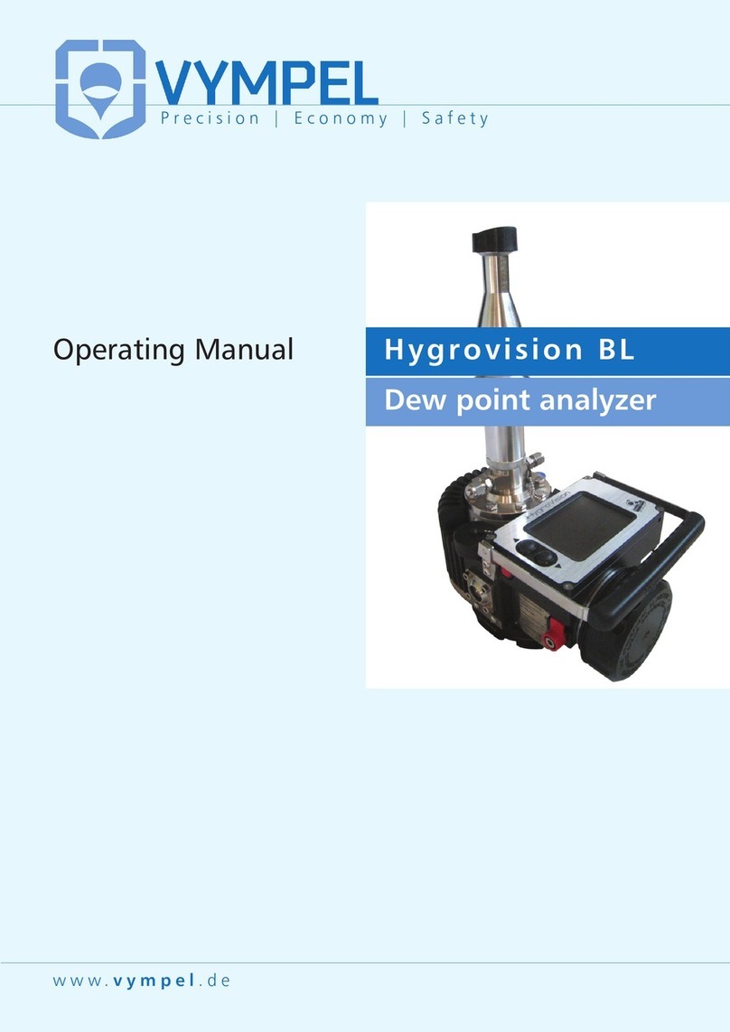
Vympel CONG Prima 2M User manual

www.vympel.de
Precision | Economy | Safety
CONG Prima 2M
Dew point transducer
Operating Manual
Vympel_OperatingManual_EN 04.07.14 09:42 Seite 1

!
Cong Prima 2M -manual
1
!
Dear Customer,
We’re pleased that you have chosen our Cong Prima 2M dew point analyzer.
***
The manufacturer guarantees that the product delivered conforms with the technical data
presented in this manual and all of the necessary safety and quality standards.
***
No part of this manual may be stored in a search system, reproduced or transmitted in any
form without the prior permission of the manufacturer. This prohibition includes, but is not
limited to, mechanical storage, photocopying, recording, etc.).
This publication does not include any license for the application of the manufacturer’s
technology.
***
Please read through this manual carefully and note in particular the limitations, instructions,
and recommendations described therein.
***
Please contact us if you have any problems, for example with the function, design or
handling of the equipment. We would also appreciate any suggestions you may have for
information to include in the operating.
We wish you much success!
Responsible for sales and maintenance in the EMEA region:
VYMPEL GmbH
Bahnstraße 17
40212 Düsseldorf
Germany
Tel.: +49 (211) 210 77 391
Fax: +49 (211) 210 77 399
e-mail: info@vympel.de
www.vympel.de
Responsible for the manufacturer:
143530, Russia, Moscow Area, Istrinskij District,
Dedowsk, Schkolnij Passage, House Nr.11
Tel.: 8 (495) 992-38-60 (ext. 219)
Fax: 8 (495) 992-38-60 (ext.217)
e-mail: vympelm100@aha.ru
www.npovympel.ru

!
"!
!
Table!of!Contents!
1"DESCRIPTION"OF"THE"CP"2M" 4"
1.1 INTENDED USE OF THE CP 2M 4
1.2 MEASUREMENT PRINCIPLE 4
1.3 CP 2M PROVISIONS FOR EXPLOSION PROTECTION 6
1.4 ANALOGUE AND DIGITAL CONNECTION PORTS 7
1.5 IDENTIFICATION AND USER INTERFACE 8
2"TAKING"DEW"POINT"MEASUREMENTS"16"
3"DESCRIPTION"AND"CONSTRUCTION"OF"THE"CONG"PRIMA"2M"18"
3.1 CONG PRIMA 2M CONFIGURATION OPTIONS 18
3.1.1 KRAY 2.848.015-01 VERSION 18
3.1.2 KRAY 2.848.015 VERSION WITH INSERTABLE SAMPLING PROBE 19
3.1.3 KRAY 2.848.015-01 VERSION WITH SGA 003 GAS PREPARATION SYSTEM 20
3.2 DESCRIPTION AND CONSTRUCTION OF THE CP 2M WITH THE SGA 003 GAS PREPARATION
SYSTEM 20
3.3 DPWAND DPHC MODULE 21
3.3.1 HIGH-PRESSURE OUTFLOW MODULE 22
3.3.2 PIPE CONNECTION MODULE22
3.4 FUNCTIONAL DESCRIPTION OF THE SGA 24
4"4."CONG"PRIMA"2M"INSTALLATION"AND"MOUNTING"25"
4.1 GENERAL INSTRUCTIONS 25
4.2 SAMPLE EXTRACTION SITE REQUIREMENTS: 25
4.3 CONNECTING THE CONG PRIMA 2M 26
4.4 CONNECTING THE CONG PRIMA 2M EQUIPPED WITH A RETRACTABLE SAMPLING DEVICE 26
4.5 INSTALLATION AND ACTIVATION OF THE CONG PRIMA 2M WITH THE SGA 003 SYSTEM 28
4.6 INSTALLATION AND CONNECTION OF A REFERENCE ANALYZER 29
5"CP"2M"ERROR"MESSAGES"30"
5.1 CLEANING THE MIRROR 32
5.2 CONG PRIMA 2M TECHNICAL INFORMATION 33
6"6."MARKINGS"35"
7"PACKING"35"
8"STORAGE"35"
9"TRANSPORTATION"36"
10"RECYCLING"36"
11"APPENDICES"#$%&$'(!)$*)+,'-$!./0%)!1$#/./$')2"
Appendix A Fehler! Textmarke nicht definiert.
Appendix B 38
Appendix C 39

!
Cong Prima 2M -manual
3
!
Appendix D 40
Appendix E 42
Appendix G 45
Appendix H 46
Appendix I 47
Appendix J 48
Appendix K 49
Appendix L 51
Appendix M 52
Appendix N 53
Appendix O 54
Appendix P 55
Appendix Q 56

!
3!
This handbook provides a description of the construction and functional principle of the
“Cong Prima 2M” dew point analyzer (also referred to as the CP 2M, transducer, analyzer or
DPA).
The CP 2M is a through-flow automatic hygrometer. It takes direct measurements with the
aid of a thermostatically controlled mirror. Dew point (dp) is established by monitoring the
reflectivity of the mirror. As the temperature of the mirror is lowered, the surface becomes
less reflective due to the formation of condensation. The temperature at which condensation
occurs is the dew point.
1 Description of the CP 2M
1.1 Intended use of the CP 2M
!
The CP2M is designed to automatically measure the dew point of water (dpW) and the dew
point of hydrocarbons (dpHC) at gas measuring facilities. It is also suitable for use in various
operations and procedures where gas quality must be monitored.
The analyzer can measure the dew point of hydrocarbons when the gas being examined
is free of water vapor that would condense at a higher temperature than that of hydrocarbons.
The analyzer can measure the dew point of water without regard to hydrocarbon
condensation temperature.
1.2 Measurement principle
!
The CP 2M makes use of the “total refraction” effect to determine the dpW.
Total refraction occurs when polarized light, with a particular orientation, passes through the
interface between a heterogeneous media (gas) and a reflective surface (thermostatically
controlled mirror) at a specific angle of incidence know as Brewster’s Angle.
When total refraction occurs no light is reflected.
The analyzer uses a laser as a source of polarized light.
The reflective surface is a dielectric condensation mirror made of silicone.
When the mirror is clean, that is when no condensation is present, as the beam of light from
the laser encounters the gas/mirror interface it is completely refracted. As a result, no light is
reflected onto the photo detector, which therefore registers a null signal.

!
Cong Prima 2M -manual
5
!
Illustration 1.1
Illustration 1.2
α– Brewster’s angle; 1 –dielectric chilled mirror; 2 –sample medium (gas); S –laser-
emitting diode; F1 and F2 –photo detectors of the registration system; U0– Zero signal from
the photo sensor.
As the mirror is chilled, droplets of water condensation begin to form on the mirror’s surface.
The rays of polarized light emitted from the laser diode are scattered when they strike these
droplets and are registered by the photo detectors (F1).
The signal created by photons hitting the detector (Illus. 2.1) is boosted and registered by the
detection system (Illus. 2.1). The signal intensity is dependent on the amount of water
condensation on the chilled mirror’s surface.
Illustration 2.1
Illustration 2.2
Light scattered by water condensation on the surface of the chilled;
1– chilled dielectric mirror; 2 –sample medium (gas)
In the absence of water vapor, hydrocarbons in the sample gas condense onto the surface of
the chilled mirror. Instead of droplets, this condensation forms a smooth film. The build up of
a cohesive film on the mirror’s surface alters the angle of incidence at which the polarized
light rays encounter the surface of the mirror.
As the light strikes the gas/condensation film interface it is partially reflected.
At the same time, due to the transparency of the condensate film, some of the light will only
be reflected at the next boundary, the interface of the condensation film with the mirror’s
4
4!
"!

!
5!
surface. As a result, the photo detector F2 receives two sets of reflected light rays, which are
slightly out of phase.
The light signal registered by the detection system produces a characteristic interference
pattern.
The intensity of the light received by the photo detector is directly dependent on the amount
of hydrocarbon condensation on the mirror’s surface. As more hydrocarbons precipitate onto
the mirror the film becomes thicker, this in turn means that the distance between the two
upper and lower boundary interfaces becomes greater. This increase in distance correlates
to a greater phase discrepancy between the two reflected rays that increases the signal
strength.
The registration of the hydrocarbon dew point temperature occurs as soon as the
condensation film reaches a thickness of 5 –10nm (default setting).
In this way, these two separate modalities generate two separate signals: the signal from
photo detector F1 is used to establish the dpW and the signal from photo detector F2 to
establish the dpHC (Illus. 3.1 and 3.2).
Illustration 3.1
Illustration 3.2
Diagram of the light scatter from a hydrocarbon film (2) on a mirror with a reflection index of n2.
1 – chilled dielectric mirror;
2– hydrocarbon condensate;
3 –sample medium (ex. gas)
1.3 CP 2M provision for explosion protection
The CP2M is certified as compliant with the requirements of EN 60079-0:2009, EN 60079-
1:2007. It carries the explosion protection marking II 2G EEx d IIA + Н2T5.
This marking identifies the CP 2M as a “flameproof enclosure” as per the requirements
stated in EN 60079-1:2007.
Explosion protection is provided by encasing the electrical elements of the electronics unit in
an enclosure that is mechanically robust and meets the standards of EN 60079-0:2009. This
enclosure can withstand explosion pressures and prevent combustion from escaping into an
ambient explosive environment.
Integrity of the flameproof enclosure is maintained through the use of threaded and
cylindrical flameproof joints. A drawing of the explosion protection measures (Appendix С)
"!
6!
4!

!
Cong Prima 2M -manual
7
!
identifies these connections as “Explosion” and lists the allowable explosion protection
tolerances according to EN 60079-1:2007.
The removable enclosure lids have an inscribed warning:
«ОТКРЫВАТЬ, ОТКЛЮЧИВ ОТ СЕТИ ~ DO NOT OPEN WHEN ENERGIZED ».
1.4 Analogue and digital connection ports
!
In order to connect the Cong Prima 2M to a technical-information measuring system or
facility, the analyzer is equipped with a serial interface.
The interface installed can be for the transmission of either analogue or digital signals
depending on the customer’s requirements.
• digital port !RS 485 Modbus
• analogue port !4 –20 mА.
The selection of either a digital or analogue information transfer port is made when the CP
2M is originally ordered.
If no specification is made with regard to interface preference, the analyzer will be delivered
with an analogue port (4 –20 mA).
Digital port: RS485:
The digital port provides for the transfer of measurement data to an external system using
the Modbus / RTU protocol (see Appendix O).
The interface is galvanically insulated (up to 500 V DC).
Analogue port 4 –20 mA:
Depending on the measurement mode selected, either the dpW or dpHC values are sent to
the interface port. The maximum impedance load on each output should not exceed 400
ohms.
The port is passive, meaning that the power supply for the CP 2M is delivered from an
external source. This connection is galvanic insulated up to 500 V DC.
The digital and analogue signals for measured dew point values (dp) correspond to the
following equation:
dp = 3.75 (I –4) –30
I = 0.267 (ТР + 30) + 4
(for water and hydrocarbons in the temperatures range: –30 °C to +30 °С)
⇒the value 4 mA corresponds to a dew point temperature (dp) of –30°С
⇒the value 20 mA corresponds to a dew point temperature (dp) of +30°С

!
7!
1.5 Identification and user interface
!
To operate the CP 2M, a magnetic key is used to select, alter, and enter parameter
values. The arrows above, below, and to both sides of the display located on the front of
the analyzer indicate the location of the buttons that are activated by the magnetic key.
The magnetic key is included with delivery of the analyzer.
Illustration 5:
CP 2M user display
The orientation of the magnetic key is shown in illustration 6.
a b
Illustration 6:
magnetically activated control buttons
(a) left -right
(b) up –down
Navigating the menu:
▲
▼
Page through the menu,
Change the displayed unit value up and down;
►
Menu point: enter
(Change between menu capitals)
◄
Leave the current menu
(Return to the higher menu point)
scroll through digits when entering a value
The menu of the Cong Prima 2M is cyclically organized, in order to make the search for
capitals or parameters simpler.

!
Cong Prima 2M -manual
9
!
The CP 2M’s menu consists of seven main headings, corresponding to the analyzer’s most
important functions (illus. 7).
When switching on the CP 2M, be sure to allow the software to fully load before taking dew
point measurements.
The software must also be fully loaded before making any menu selections.
«measure: HC»
In this mode, the CP 2M measures the value of dew point of hydrocarbons (dpHC).
Confirm this selection by touching the «►» button with the magnetic key.
To end this selection, touch the «◄» button.
«measure: W»
In this mode, the CP 2M measures the dew point of water (dpW).
Confirm this selection by touching the «►» button.
To end this selection, touch the «◄» button.
«measure: W & HC»
In this mode, the CP2M alternately determines the dpHC and the dpW.
Confirm this selection by touching the «►» button.
To end this selection, touch the «◄» button.
«calibr: HC»
This activates the calibration mode of the hydrocarbon measurement channel.
Using this function, the operational sensitivity of the dpHC measurement channel can be
adjusted as desired.

!
48!

!
Cong Prima 2M -manual
11
!
Illustration 7: CP 2M main menu

!
4"!
«param. view»
In the “param. view” function, the current operational parameters of the CP 2M can be
checked and adjusted.
This sub-point has four configuration options for operating parameter groups that directly
affect the accuracy of the measurement process and the information displayed. The
operating parameter groups are selected by touching the «▲» and «▼» buttons with the
magnetic key, and activated by touching the «►» button.
Touch the «◄» button to return to the main menu.
The parameters are subdivided into the following function groups:
«GENERAL PARAM.»
Parameter group for the algorithm that defines the general
operation of the CP 2M;
«W CYCLE PARAM.»
(Water cycle)
Parameter group for the algorithm that defines the
measurement of the dew point of water (dpW);
«НС CYCLE PARAM.»
(Hydrocarbon cycle)
Parameter group for the algorithm that defines the
measurement of the dew point of hydrocarbons (dpHC);
«LINK PARAM»
(Parameter transfer)
Parameter group that defines the transfer of data via
ModBus/RTU protocol;
Warning!
Each modification of the CP 2M parameters can permanently
compromise the analyzer’s performance.

!
Cong Prima 2M -manual
13
!
The following parameters are preset:
Baud rate
-data transmission rate = 38,400
Parity
-none
Stop bits
-1
Address
-corresponds to the address of the device –100
(In networks with multiple devices, the analyzer’s address can be set at a value of 1 to 247.)
A complete list of all the factory default settings for the various parameters of the CP 2M can
be found in Appendix E.
Use the «▲» or «▼» button to select a specific parameter within a particular sub-menu.
Confirm the selection by touching the «►» button.
Changes in parameter values can be made using the following control commands:
►
open/ close a menu for making adjustments to parameters
(a blinking “x” appears in the display)
◄
Change the type of parameter (move the cursor)
▲(▼)
Change the parameter value
►
Confirm the new value (the cursor “x” doesn’t blink)
◄
Return to the menu point one step higher in the hierarchy
Please note:
A password is required to access the menu point for changing parameter settings.
The window in which to enter the password appears in the display when a change to a
parameter value is entered. The password access window also appears when the service
menu is opened.
In addition, the password is required when the CP 2M started or restarted.

!
43!
«Cleaning mode»
This mode triggers the cleaning of the thermostatically controlled mirror.
Cleaning the mirror involves heating of the mirrors surface to a set temperature (Parameter
Т(°С) –i.d.R. +55°C).
In this mode the display shows the following information: (illus. 7):
current temperature of the CP 2M’s mirror Т;
current signal value for water Uw;
current signal value for hydrocarbons Uhc;
current housing temperature of the CP 2M B.
Illustration 7:
Cleaning mode menu
Select the respective sub-menu point using the «◄» button.
To exit the cleaning mode, touch the «►» button.
Finally, select the «measure: W» to determine the dpW value or the «measure: HC» mode
to determine the dpHC value.
«Service Menu»
The «Service Menu» provides the operator with access to the CP 2M’s service functions. A
password is required in order to access this (illus. 8 -10).
Illustration 8:
Password entry
The factory default service menu password code is «11111».

!
Cong Prima 2M -manual
15
!
Illustration 9: «Service menu» sub-menus
«Restart now»
The “Restart now” function initiates a pre-programmed re-start of the analyzer.
Warning!
If the password is lost, the analyzer must be returned to the manufacturer for reprogramming
to restore access to the service menu.
«Service Def.Par»
This function resets the analyzer to the factory settings. When the operator selects and
confirms this function the message: «FACTORY DEFAULTS» is shown on the display.
In order to save the current parameter settings to the CP 2M’s memory select «PARAM.
SET» using the «►» button and to confirm the selection touch the «►» button a second time.
Please note that the current CP 2M parameters may be different from the factory settings
(default parameters).
«Current version»
This function serves to check the version of the software and the check-sum of the CP 2M.
In this mode, the software version and the software check-sum are shown on the display.
(illus. 10):
Illustration 10: Software version and software checksum
«Test 4 … 20mA»
The “Test 4…20mA” function is used to check and adjust the CP 2M analogue data port.
Use the «▲» and «▼» buttons to set the output value (between 3.5 and 24 mA). The setting
can be adjusted gradually in 0.5 mA increments.

!
45!
2 Taking dew point measurements
The Cong Prima 2M requires a secure power supply of 24V, connected to the analyzer at
terminal block 1 and 2 (Appendix A).
Once the analyzer is connected to the power supply and switched on, the operating software
immediately begins to load.
After the start-up sequence is completed, the CP 2M is ready for operation and is
automatically set to the main menu (illus. 11).
Illustration 11
(a) for dpW measurements
(b) for dpHC measurements
Depending on whether the target value is the dew point of water dpW (a) or hydrocarbons
dpHC(b).
Until the first dew point measurement is made and a dp value is determined, “NO” will be
shown on the display. (illus. 10)
In the case of both water and hydrocarbons, the initial electrical signal at the analogue 4…20
mA data port is 3.5 mA for a value of “NO”.
A small flashing letter is shown in the upper left-hand corner of the display. This letter
provides information about the operation currently underway within a given mode.
d
Diagnostic cycle for elements of the dew point measurement channel;
s
Mirror heating during the measurement cycle and temperature stabilization;
с
Mirror cooling;
h
Mirror heating;
сal
Calibrating the dpHC measurement channel;
After the measurement cycle is completed, the registered value for the dew point of water
dpW or hydrocarbons dpHC will be presented on the display (illus. 12).
The Cong Prima 2M then switches to “mirror cleaning” mode automatically.

!
Cong Prima 2M -manual
17
!
(a) dpHC
(b) dpW
Illustration 12
Examples of the display after the first measurement cycle.
After the “mirror cleaning” cycle is completed, the analyzer carries out a self-diagnostic cycle.
Then, when this cycle is complete, the unit repeats the measurement cycle starting from the
beginning.
If the measured dew point value lies below the CP 2M’s measurement range, the following
message will be shown on the display (illus. 13):
Illustration 13
CP 2M display for a dpW outside the analyzer’s measurement range.
In the hydrocarbon measurement mode (dpHC), if water condenses before hydrocarbon
condensation can be registered, the analyzer’s display shows the following message:
Illustration 14
CP 2M display for dpHC outside the analyzer’s available measurement range.
At this point, the CP 2M automatically ends the measurement cycle and switches to the
mirror-cleaning mode.
Subsequently, the analyzer starts the next measurement cycle.

!
47!
3 Description and construction
of the Cong Prima 2M
The Cong Prima 2M dew point analyzer comprises the sensor cell (1), the housing (2), lids A
(3) and B (4), the gas supply line (5) and an electronics unit, which is located within the
housing (2) (see Appendix B).
The analyzer is equipped with four magnetically activated buttons, which are arranged above,
below, and to either side of the display screen. These buttons are operated using a specially
designed magnetic key.
The CP 2M’s display screen shows the current dew point measurement values, dpW or
dpHC, and other information about the status of the device.
The terminal block of the analyzer’s transformer is covered by lid B. The RS485 or
4 –20 mA data ports are located in the terminal block, which is also the pint of connection for
the four-conductor power cable. The power cable passes through the housing into the
electronics unit by way of the cable inlet (8).
The numbers and uses of the terminals are given in appendix A.
The CP 2M is attached to the gas supply line with eight stainless steel M8 screws (6). The
construction of the analyzer permits easy access to the thermostatically controlled mirror for
cleaning and maintenance purposes. Gas delivery to the CP 2M’s measurement chamber
must be interrupted for the duration of these procedures.
3.1 Cong Prima 2M configuration options
!
The Cong Prima 2M dew point analyzer is available in three versions with different
configurations.
3.1.1 KRAY 2.848.015-01 version
(Appendix B)
The KRAY 2.848.015-01 version consists of a measurement module with no pre-installed
system for gas delivery, filtration or outflow.
This module is particularly suited for applications in laboratories and industrial areas where
gases are characterized by a high degree of purity.
The KRAY 2.848.015-01 version can also be installed as a dew point analyzer in
measurement systems that are already installed.

!
Cong Prima 2M -manual
19
!
3.1.2 KRAY 2.848.015 version equipped with
insertable sampling probe
(Appendix C)
Some configurations of the Cong Prima 2M dew point analyzer are equipped with an
insertable gas-sampling probe.
The insertable sampling probe makes it possible to mount the analyzer directly onto the gas
line (min. ø 200mm) and ensures that the gas sample is clean.
This version of the analyzer is suitable for use in gas transport facilities and other
installations where the composition of the gas does not include liquid contaminants
(aerosols).
The gas delivery unit is outfitted with a cut-off valve. Thank to this valve, it is not necessary to
interrupt pipeline gas flow when the analyzer is temporarily uninstalled, for example for
maintenance procedures.
In addition, the KRAY 2.848.015 version has a fine-tuning valve used to adjust the volume
flow of sample gas to the CP 2M’s measurement chamber.
a) Insulated hood
b) Weather shade
Illustration 14:
CP 2M protective equipment for outdoor installations
For outdoor installations, it is recommended that the CP 2M KRAY 2.848.015 be outfitted
with the insulated hood or weather shade included with delivery, in order to protect it from the
effects of inclement weather. The insulated hood prevents excessive cooling of the CP 2M’s
measurement chamber and sample delivery pipe by retaining the heat generated by the
measurement process as well as ambient heat within the gas pipeline (illus. 14). The
insulated hood and weather shade are included with delivery in the KRAY 2.848.015 version
of the Cong Prima 2M.
Table of contents
Other Vympel Measuring Instrument manuals