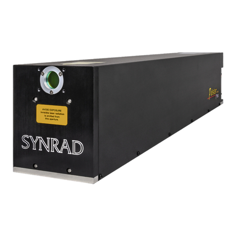
Novanta Synrad ti Series User manual

1 QSG ti-Series™ Water Cooled Laser, FH Marking Head, kit & WMPv6 Ver 2.0
FH
MARKING HEAD
FLYER
a Novanta company
ti-Series™ Water Cooled Laser, FH Marking Head, kit & WMPv6
1. Under your ti Series laser at the bottom of the box you will nd the mounting hardware/compo-
nents kit. The Marking Head hardware/components kit is located in the top shipping compo-
nents box. Don’t forget to save all shipping containment including plug covers and set them aside.
Important
Note:
Keep All Foam and Packaging, you will need to re-use it when moving your laser to
prevent damage that could void your warranty. Refer to this guide and the Technical
Reference chapters in the laser’s Operation Manual when re-packaging for shipping
and/or relocation. Remove all accessory items not originally attached to the laser prior
to re-packaging for shipping.
2. Upon arrival, inspect all shipping containers for signs of damage. If you discover shipping damage,
document the damage (photographically if possible), then immediately notify the shipping
carrier (responsible party for any transportation damage) and SYNRAD®. See the inventory section
with in the Introduction chapter of the Operation Manual for packaging list(s).
Laser and Marking Head Unpacking:
Note: If shipped completely assembled, jump to the cooling section of this guide.
Important
Note: Read all Danger, Warning, Caution terms, symbols, and instructions located
in the (Laser Safety Hazard information) sections in the ti-Series Laser Operation Man-
uals located on our website http://synrad.com/synrad/docroot/resources/libraries/
manuals.
1.1 Lifting the ti-Series laser correctly by
holding in the middle, do not carry laser
by the mounting feet, this can disturb
alignment.
1.2 Ti-Series laser mounting/component kit
for the laser and the FH FlyerMarking Head
(Inset).

a Novanta company
ti-Series™ Water Cooled Laser, FH Marking Head, kit & WMPv6
2 QSG ti-Series™ Water Cooled Laser, FH Marking Head, kit & WMPv6 Ver 2.0
Important
Note:
Caution! When packing the marking head for relocation or shipment, noth-
ing can be on the sides of the unit at any time as damage will occur. All box
components must be stowed as they were when they arrived.
2.1 Place the unit with foam packaging on a
rm surface, remove foam end cap,
notice foam notch locations for ports
and interfaces.
Lift both the both the marking
head and the foam packaging out
of the box.
Please refer to the examples above and the laser’s Operation Manual drawings located at the end of
the Technical Reference Chapter.
The wire harness can be damaged in
shipping if not re-packaged as shipped!
Top Foam
notch
Bottom
Foam notch
Don’t forget to remove the three (3) cap
screws on the lens aperture cover if a
focusing lens is ordered.

3 QSG ti-Series™ Water Cooled Laser, FH Marking Head, kit & WMPv6 Ver 2.0
FH
MARKING HEAD
FLYER
a Novanta company
ti-Series™ Water Cooled Laser, FH Marking Head, kit & WMPv6
Laser Unpacking:
Important
Note:
Caution! Unpacking the wire harness incorrectly can damage the laser.
Keep All Foam and Packaging, you will need to re-use it when moving your
laser. Refer to this guide and the Getting Started/Technical Reference chap-
ters in the laser’s Operation Manual when re-packaging for shipping and/or
relocation.
Caution! When packing the laser for relocation or shipment, nothing can be on the sides
of the laser at any time as damage will occur. The skin on the sides of the laser is fragile!
All box components must be stowed under the laser.
The wire harness will be damaged in shipping if not re-packaged as shown above.
3. Unseat the wiring by sliding the harness out of the notch, then down and out of the foam as shown
above.
3.1. Locate the wire harness in
side one of the foam end caps.
3.3. Drape the wire harness across
the top of the laser housing when
carrying.
3.4. Don’t forget the hardware
at the bottom of your box!
3.2. Push the wire harness through the
notch in the foam.
4. Locate the laser hardware kit at the bottom of this box under the laser.

a Novanta company
ti-Series™ Water Cooled Laser, FH Marking Head, kit & WMPv6
4 QSG ti-Series™ Water Cooled Laser, FH Marking Head, kit & WMPv6 Ver 2.0
Mounting your Laser:
Note: Mounting feet and/or rails are optional, for complete details, refer to the Ti Series Operator’s
Manual. Remove the laser aperture self-adhesive lm before mounting to the rail.
Don’t tighten the path enclosure screws until the laser is mounted securely to the rail.
SYNRAD does not recommend mounting lasers in a vertical, (head and/or tail down) position. Please
contact the factory for limitations as a vertical orientation increases the risk of damage to the lasers optics.
The laser’s mounting feet are precisely aligned and shimmed at the factory to ensure alignment between
the marking head and the Mounting Rail. Do not loosen or remove the mounting feet from the laser.
See the FH Flyer Marking Head Operator’s Manual for further details.
5. Before mounting the laser to the rail, ensure the aperture seal is removed.
6. Locate the Mounting Hardware Kit ( ) path enclosure tube, marking head & laser
hardware.
DB9
CONNECTOR
AUXILIARY
POWER
DC POWER
CABLES
POWER
LED
LASE LED
FUSE
KEYSWITCH
PWR LASE
CTRL
FUSE
CARBON DIOXIDE LASER
ON
5 SEC DELAY
COMMAND
INPUT
STATUS
LASER EXIT
APERTURE
SHUTTER
SWITCH
DIODE POINTER
POWER CONNECTOR
ON OFF
APERTURE
SEAL
INVISIBLE LASER RADIATION
IS EMITTED FROM THIS
APERTURE
AVOID EXPOSURE
OPTICAL
ACCESSORY
MOUNTING (x6)
O
F
F
A
V
O
ID EXP
OSU
RE
5.1 Remove the
aperture seal.
6.1 Path enclosure tube.
6.2 6-32 x 1” Laser Mounting socket head
capscrews.
6.3 1/4-20 x 3/4” Marking Head Mounting
socket head capscrews.
6.4 8-32 x 1/4” Marking Head Mounting
button head socket screws.
6.5 Laser & Marking Head Mounting Kit(s).

5 QSG ti-Series™ Water Cooled Laser, FH Marking Head, kit & WMPv6 Ver 2.0
FH
MARKING HEAD
FLYER
a Novanta company
ti-Series™ Water Cooled Laser, FH Marking Head, kit & WMPv6
Notch
8.2 l-bracket mounting holes and notch locations
on the rail.
Note: Assure the rail notch is on the Marking Head
side of the rail.
Notch
3
12
4
8.3 Secure the l-bracket to the
rail.
7. Remove the dust cover & set aside, from the rear end of the marking head, unwrap the mounting
rail, set it on a rm surface. Orient the rail so that the l-bracket can be placed on the notch end of
the rail.
8. Mount the l-bracket to the rail using the (4) 1/4-20 x 3/4” socket head capscrews as shown in the
following gures.
8.1 Notch end of the rail.
Marking head side
of the rail.
Laser feet Dowel pins.
7.1 Dust Cover

a Novanta company
ti-Series™ Water Cooled Laser, FH Marking Head, kit & WMPv6
6 QSG ti-Series™ Water Cooled Laser, FH Marking Head, kit & WMPv6 Ver 2.0
9.1 Marking Head secured to
the L-bracket.
Mounting your Marking Head onto a Rail (Continued):
9. Remove the dust cover & set aside, from the rear end of the marking head, unwrap the mounting
rail, set it on a rm surface. Orient the rail so that the L-bracket can be placed on the notch end of
the rail.
Dowel pins
Important
Check Point: The anodized blanking plate & dust cover are removed from the Marking Head.
The Marking Head is mounted adjacent to the notch on the rail.
Refer to the appropriate chapter for more mounting details and the technical
drawings in the Ti Series Operation Manual.

7 QSG ti-Series™ Water Cooled Laser, FH Marking Head, kit & WMPv6 Ver 2.0
FH
MARKING HEAD
FLYER
a Novanta company
ti-Series™ Water Cooled Laser, FH Marking Head, kit & WMPv6
1
2
Mounting your Laser onto a Rail:
10. Ease the laser forward so the dowel pins on both mounting feet drop into their respective holes on
the rail. Install/tighten the four (4) 6/32 x 1” socket head capscrews. See the gure below.
10.1 Attach the laser by it’s mounting feet securely to the rail.
Important
Note:
Calibration void if shim bolts are adjusted, if your laser has mounting feet as shown
above, careful not to carry or handle the laser by the feet to minimize misalignment risk.
3
4
Important
Note: Do not use any type of jackscrew arrangement as this will twist the baseplate and
may distort the tube.

a Novanta company
ti-Series™ Water Cooled Laser, FH Marking Head, kit & WMPv6
8 QSG ti-Series™ Water Cooled Laser, FH Marking Head, kit & WMPv6 Ver 2.0
9. After both the laser and the marking head are mounted to the rail, place the spring-loaded path
enclosure tube as shown below.
Note: The recommended mounting orientation for the ti Series is horizontal.
Refer to the drawings within the Ti Series Operation Manual, see the
Technical Reference chapter for further information.
Important
Note:
Consult the factory for further mounting angle guidance outside >20% from the
horizontal. When mounting the laser, use only one metric or SAE fastener per
mounting tab on the baseplate. Do not use any type of jackscrew arrangement
as this will twist the baseplate and may distort the tube.
9.1 Compress the spring-loading path enclosure
tube and place the larger end facing the mark-
ing head (on the L-bracket).
Mounting your Laser onto a Rail (Continued):

9 QSG ti-Series™ Water Cooled Laser, FH Marking Head, kit & WMPv6 Ver 2.0
FH
MARKING HEAD
FLYER
a Novanta company
ti-Series™ Water Cooled Laser, FH Marking Head, kit & WMPv6
10. Secure the path enclosure tube to the L-bracket with four (4) 8-32 x 1/4” button head socket screws
as shown below.
Mounting your Laser onto a Rail (Continued):
10.1 Assure the laser & marking head is securely mounted to the rail beforehand.
10.2 Should look like this.
1
2
34
Not shown

a Novanta company
ti-Series™ Water Cooled Laser, FH Marking Head, kit & WMPv6
10 QSG ti-Series™ Water Cooled Laser, FH Marking Head, kit & WMPv6 Ver 2.0
Cooling:
Important
Note:
Use distilled water as the coolant. If glycol is necessary, add no more than 10% by
volume. When filling your chiller, use at least 90% distilled or tap water by volume. If
you must use glycol, do not add more than 10% by volume. See the technical reference
chapter in the ti Series Operation Manual for the dew point table and cooling specifica-
tions.
11. Locate the Ship Kit ( ) Cooling quick-disconnect ttings and 1/2 inch polyethylene
tubing. See the 48-1/48-2 Cooling connections (rear interface) in the gure below.
Operating the laser with a coolant temperature below the dew point of the surrounding air may cause
condensation to occur that will damage the laser! The setpoint temperature MUST be maintained above
the dew point temperature.
Water In
from chiller
Water Out
to chiller
Attention: The stability of the unit will be aected
if the water in/out is reversed and if not
run in parallel!
When coolant temperature is lower than the dew point (the temperature at which moisture condens-
es out of the surrounding air), condensation forms inside the laser housing leading to failure of laser
electronics as well as damage to optical surfaces.
The greatest risk of condensation damage occurs when water-cooled lasers are run in a high heat/high
humidity environment and the chiller’s coolant temperature is colder than the dew point temperature of the
surrounding air or when the system is shut down, but coolant continues to ow through the laser for ex-
tended periods of time.
The chiller’s temperature setpoint must always be set above the dew point temperature. In cases where this
is not possible within the specied coolant temperature range of 18 °C to 22 °C (64 °F to 72 °F), then the fol-
lowing steps MUST be taken to reduce the risk of condensation damage.
A. Stop coolant ow when the laser is shut down.
B. Increase coolant ow by an additional 3.8 LPM (1.0 GPM).
C. Air-condition the room or the enclosure containing the laser.
D. Install a dehumidier to reduce the humidity of the enclosure containing the laser.

11 QSG ti-Series™ Water Cooled Laser, FH Marking Head, kit & WMPv6 Ver 2.0
FH
MARKING HEAD
FLYER
a Novanta company
ti-Series™ Water Cooled Laser, FH Marking Head, kit & WMPv6
Cooling (Connued):
Guidelines for cutting and installing tubing
Cut tubing lengths generously to allow for trimming.
Cut tubing squarely; diagonal cuts may not seal properly. Trim away any burrs if the cut is “ragged”.
Avoid excessive stress on ttings by creating a gentle radius when bends in the tubing are close to
ttings. Bending tubing too sharply will compromise the sealing properties of the tting.
Never allow the tubing to kink, since kinking severely restricts coolant ow.
Push tubing completely into the tting, then pull the tubing to verify that it is locked into place.
If tubing needs to be disconnected from a tting:
First push and hold the tubing slightly into the tting. Next push the white tting ring evenly towards
the tting, and then pull the tubing free.
After disconnecting tubing from a tting, trim 12.7 mm (0.5 in) from its end before reconnecting.
Trimming the end of the tubing before reconnecting provides an undisturbed sealing surface.
If your integrated laser application uses metric cooling tubing, we recommend the installation of
tubing adaptors to convert cooling kit ttings from 1/4”tubing to 6 mm metric tubing and 3/8”
tubing to 8 mm metric tubing. These tubing adaptors are available from many tubing and tting
manufacturers.
Important
Note: Choosing the correct coolant temperature is important to the proper operation and lon-
gevity of your laser otherwise internal condensation damage will occur!
Reference the dew point chart for temperatures and range of air temperature and relative humidity values
in the technical references chapter of the Operation Manual.
Remember that the laser’s coolant temperature must be set above dew point temperatures.
Do not ow coolant through the laser for an extended period of time
when the laser is shutdown. This causes condensation to form inside the
laser which may result in catastrophic damage to internal optics and elec-
tronic circuits.
Inlet cooling water temperature must always be maintained above the
dew point to prevent condensation and water damage to your laser.
Caution
possible equipment
damage

a Novanta company
ti-Series™ Water Cooled Laser, FH Marking Head, kit & WMPv6
12 QSG ti-Series™ Water Cooled Laser, FH Marking Head, kit & WMPv6 Ver 2.0
Note: The negative (–) side of the DC input to the laser is internally connected so that the laser chassis
serves as DC power ground.
Power Connections:
12. Verify that input AC power to the DC power supply is physically locked out or disconnected.
13. Connect the Marking Head DC power VDC cable into the Marking Head’s power supply.
You should isolate the laser’s DC power supply so that the only grounded connection is at the laser.
Alternatively, you can mount the laser chassis on an insulating pad or lm in order to electrically isolate
the DC return from the chassis ground.
13.1 DC Power connection locations
(for the Marking Head) to the
power supply.
Green
( )
Red
(+)
Black
(-)

13 QSG ti-Series™ Water Cooled Laser, FH Marking Head, kit & WMPv6 Ver 2.0
FH
MARKING HEAD
FLYER
a Novanta company
ti-Series™ Water Cooled Laser, FH Marking Head, kit & WMPv6
14.1 DC Power
Power Connections (Continued):
Do not reverse polarity when connecting the DC Power cable between the DC power supply and the
ti-Series laser. Damage to the power supply may occur!
Because AC input connections and requirements vary from facility to facility, customers must provide the
AC power cable or wiring.
Attach the red (+) wire(s) from the DC Power cable to the positive (+) 48 VDC output terminal and attach
the black (-) wire(s) from the DC Power cable to the negative (-) 48 VDC output terminal.
14. Connect the negative (black) and the positive (red) DC power into the laser’s power supply.
15. Connect one side of the 180–264V AC line to the input terminal labeled “AC/L”.
Important
Note:
16. Connect the other side of the AC line to the input terminal labeled “AC/N”.
17. On the AC input section of the PS-48 power supply, connect the ground wire, typically green, to the
input terminal labeled with the ground symbol.
The ti-Series laser requires a DC power supply capable of providing 48 VDC at 18-35 A
depending on model, refer to the specications within the laser’s operation manual.
For the ti-Series laser, SYNRAD® recommends the PS-48 DC power supply which pro-
vides a maximum of 50A at 48 VDC. AC input requirements for the PS-48 supply are
180-264 VAC, single phase (1Ø), 9.4 A max (@208 VAC), 47-63 Hz. Please refer to the
corresponding power supply manual located on our website.

a Novanta company
ti-Series™ Water Cooled Laser, FH Marking Head, kit & WMPv6
14 QSG ti-Series™ Water Cooled Laser, FH Marking Head, kit & WMPv6 Ver 2.0
Control Connections:
18. Connect the laser’s control BNC interface to the Marking Head’s laser control port.
BNC
Connector
Important
Note:
All control connections to Firestar ti-Series lasers are made through the 15-pin User
I/O connector on the laser’s rear panel. The User I/O port receives power commands
from SYNRAD’s UC-2000 Universal Laser Controller, or FH marking head, and also
serves as the connection point for auxiliary signals between the laser and any parts
handling, automation, or monitoring equipment.
Always use shielded cable when connecting your PWM Command signal
source to PWM Positive/PWM Negative inputs.
In electrically-noisy environments, long lengths of unshielded wire act like
an antenna and may generate enough voltage to trigger un-commanded
lasing.
Warning
Serious
personal
injury
81.1 Assure the ferrite bead is
on the Marking Head side.

15 QSG ti-Series™ Water Cooled Laser, FH Marking Head, kit & WMPv6 Ver 2.0
FH
MARKING HEAD
FLYER
a Novanta company
ti-Series™ Water Cooled Laser, FH Marking Head, kit & WMPv6
19.1 Control connection locations
(for the Marking Head).
19. Connect the other end of the BNC cable to the control input, 15 pin User I/O, via the Quick Start
Plug QSP (Optional) located on the rear end of the laser. (Refer to the gure on the following page.)
20. The Ethernet connector is ready to be plugged into the PC’s Ethernet port and the USB cable is ready
to be plugged from the FH Flyer Marking Head to the PC.
Control Connections (Continued):
QSP (optional)
and BNC
To PC
USB port
20.1 To PC Ethernet port
Caution: The Quick Start Plug bypasses the laser’s safety interlock function, potentially
exposing personnel to hazardous invisible laser radiation.

a Novanta company
ti-Series™ Water Cooled Laser, FH Marking Head, kit & WMPv6
16 QSG ti-Series™ Water Cooled Laser, FH Marking Head, kit & WMPv6 Ver 2.0
To PC
Ethernet
port
BNC
Connector
Should look something
like this.
DC
Power
19.2 From laser I/O port to Marking Head BNC port.
QSP (optional)
and BNC

17 QSG ti-Series™ Water Cooled Laser, FH Marking Head, kit & WMPv6 Ver 2.0
FH
MARKING HEAD
FLYER
a Novanta company
ti-Series™ Water Cooled Laser, FH Marking Head, kit & WMPv6
Laser Markers are pre-congured at the factory to a xed address of 192.168.100.100. This allows you to
make a peer-to-peer Ethernet connection. Your computer’s Ethernet settings are determined by your facil-
ity’s computer network. The FH Marking Head requires a connection to a computer with a static IP address
if not connected to a local network (Peer to Peer). Reference the FH Flyer Operation Manual located on our
website for more information.
Set your computer’s static IP address
21. Disconnect the computer from your local network.
22. Turn o Dynamic Host Conguration Protocol (DHCP), if enabled, and create a static IP address for
your computer.
Note: The exact steps may vary depending on your operating system.
a
From the Start menu, go to Settings and choose Network Connections.
b
Double-click on the appropriate Local Area Network (LAN).
c
Locate the LAN’s Internet Protocol (TCP/IP) properties.
d
Select “Use the following IP address:” and enter the following information:
IP Address: 192.168.100.101
Subnet Mask: 255.255.255.0
e
Click OK to submit the changes.
Control Connections (Continued):

a Novanta company
ti-Series™ Water Cooled Laser, FH Marking Head, kit & WMPv6
18 QSG ti-Series™ Water Cooled Laser, FH Marking Head, kit & WMPv6 Ver 2.0
17. Before upgrading to a newer version of WinMark pro, backup all existing .mkh mark les and unin-
stall prior version(s) of WinMark pro software.
18. Download the latest version 6 WinMark pro driver from our website https://www.synrad.com/syn
rad/docroot/products/marking_heads_software/winmark-sw. Exit all programs prior to Installation.
19. To install WinMark pro v6, and associated device drivers on a Windows®7 or Windows®Vista™operat-
ing system, right-click the setup.exe le and choose ‘Run as Administrator…’.
(WinMark®) v6 Software Installation:
20. To install WinMark Pro v6, and associated device drivers, on a Windows®operating system, double-
click the setup.exe le.
21. WinMark Pro v6 is a Microsoft .NET™ Framework-based application. If Microsoft .NET Framework
Service Pack 1, or higher, is not installed on the computer, the installer will prompt you to click ‘Ac-
cept’ to install the .NET Framework. You must have the .NET Framework runtime and associated les
installed to run WinMark Pro.
Important
Note: When upgrading from a v4 build to version v6, the WinMark Pro installer automatical-
ly performs a “clean install” because v6 is uses a dierent subset of registry keys. The
“Perform Clean Installation” and “Keep Current Program Settings” options are grayed
out to indicate this installation is a“clean installation”.
Upgrading from one v6 build to another does allow the option of preserving existing WinMark settings
in the computer’s System Registry. Choose Yes to preserve current WinMark Pro v6 registry settings
including custom date code formats, object defaults, shift codes, auto startup info, and saved serial
numbers. Choose No to erase all previous WinMark v6 Registry entries and perform a clean installation.
Note: Due to Microsoft’s implementation of registry virtualization, Windows Vista may re-
quire you to log on as an Administrator to perform certain functions like le impor-
tation or to save custom date code formats.
Laser Marking Software (WinMark®):
Important
Note:
Prior to installation of the WinMark pro laser marking software on your computer,
review the requirements in the WinMark pro Operation Manual, remove power or
unplug the USB cable from the FH Flyer marking head to prevent windows from ar-
bitrarily assigning a USB driver that is not compatible with Flyer’s USB port protocols.
Note: Find the WinMark pro v6 Software release notes on our website. Refer to
WinMark’s website for supported operating systems and the WinMark Pro
Operation Manual.

19 QSG ti-Series™ Water Cooled Laser, FH Marking Head, kit & WMPv6 Ver 2.0
FH
MARKING HEAD
FLYER
a Novanta company
ti-Series™ Water Cooled Laser, FH Marking Head, kit & WMPv6
WinMarkpro v6 Installation (continued):
Note: If WinMark Pro is un-installed, the .NET package is not removed, because these les may be
used by other applications installed after the original WinMark installation.
22. When the .NET Framework installation us complete, reboot if prompted to do so. Otherwise the Win-
Mark installer will continue.
23. If Microsoft C++ Redistributable x86 le runtime components are not installed on the computer, the
installer will prompt you to click ‘Install’ to install C++ Redistributable les. You must have these les
installed to run WinMark Pro.
24. Follow instructions in the installer dialog boxes to complete the WinMark Pro installation. You must
click ‘I Agree’ to accept the WinMark Pro license agreement and continue the installation.
25. After installation is complete, remember to turn on any anti-virus software.

a Novanta company
ti-Series™ Water Cooled Laser, FH Marking Head, kit & WMPv6
20 QSG ti-Series™ Water Cooled Laser, FH Marking Head, kit & WMPv6 Ver 2.0
WinMark Launcher:
26. As part of the software installation, WinMark Launcher (Launcher.exe) is placed in the Program Files/
WinMark folder and a shortcut is placed on the desktop. Launcher allows non-administrative
operators to load existing .mkh les for marking without opening WinMark’s Drawing
Editor by selecting the ‘Open Drawing...’ from the le menu.
27. To add an Admin password so operators cannot modify a drawing select ‘Modify Drawing...’ which
then opens the WInMarkpro application.
26.1 Opening an existing *.mkh le.
27.1 Modifying an existing *.mkh le.
27.2 Opening WinMarkpro through the Launcher.
Table of contents
Other Novanta Measuring Instrument manuals

Novanta
Novanta ATI Axia80 User manual
Novanta
Novanta vi30 User manual

Novanta
Novanta SYNRAD Pulstar p100 User manual

Novanta
Novanta i401 User manual

Novanta
Novanta f201 User manual

Novanta
Novanta v30 User manual

Novanta
Novanta 32-1 Laser User manual
Novanta
Novanta i401 User manual

Novanta
Novanta p400 OEM Series User manual
Novanta
Novanta ventus with mpc6000 User manual

