Vympel Hygrovision BL User manual

Precision | Economy | Safety
www.vympel.de
Hygrovision BL
Dew point analyzer
Operating Manual
Vympel_OperatingManual_EN 04.07.14 09:42 Seite 2

!
!"#$"%&'&()*+,-./.,#&01&'&234567899::;3<&
"!
!"#$%&'(&)'*!%*!+&
,-!.%*%/"$&0%+)/12!1'*& 3!
,-,-!24/2'+%&"*0&(1%$0&'(&"22$1)"!1'*& 3!
"#$"%&'! (!
)*'+,!%)!-""+*.-/*%0! (!
/1"'&!%)!*0&/-++-/*%0&! (!
*0&/-++-/*%0!-0,!%"'$-/*02!$'3#*$'4'0/&! (!
,-5-!%62$'+1'*&2/'!%)!1'*& 7!
,-8-!9%"+4/%9%*!&2/1*)12$%&,:!
,-;-!"*"$<=%/&)'*+!/4)!1'*&,5!
5-//'$1!"-.6!78!
,->-!"*"$<=%/&2'?%/&+422$<&,8!
,-@-!"001!1'*"$&)'92'*%*!+&"*0&"))%++'/1%+&,;!
4*.$%&.%"'!79!
2:;!<=>?!@!A:;!BCD;;ECD!F>GHC>=!;I;HDJ!K4>LD=!MM7N! 79!
2-&!,'+*O'$1!&1&/'4! ! 4%,'+!MM7!7P!
"-$/*.+'!)*+/'$!7P!
2+1.%+&!-0,!Q'-O1!Q1,$%.-$5%0&!)*+/'$!7P!
'R/'$0-+!"%S'$!&#""+1!.-5+'!7T!
*$!-,-"/'$!7T!
&#""+'4'0/-+!.%%+*02!&1&/'4!7(!
/$*"%,!7(!
&-4"+'!2-&!'R/$-./*%0!&1&/'4!7(!
Q*2QU"$'&&#$'! ! O'0/*02!4%,#+'!7V!
2-&!"$'"-$-/*%0!&1&/'4! ! &2-UMM8!7V!
,-3-!)'*!/'$&"*0&01+2$"<&%$%9%*!+&5:!
,-A-!!B%&"*"$<=%/C+&9%*4&5:!
/#$0*02!%0!/Q'!-0-+1W'$!XM!
,*&"+-1',!*0)%$4-/*%0!XX!
"$%"'$/*'&!XX!
-0-+1W'$!.Q'.6!XY!
-#/%4-/*.!,'S!"%*0/!4'-&#$'4'0/!4%,'!XY!
/#$0*02!%))!/Q'!-0-+1W'$!X9!
,-7-!)'**%)!1*.& & 2%/12B%/"$&0%D1)%+&5@!
,-,:-!+2%)1(1)"!1'*+&5A!
,-,,-!B<./'D1+1'*&#$&+!"*0"/0&%E4129%*!&8:!
,-,5-!%62$'+1'*&+"(%!<&2/'D1+1'*+&85!
5-!+"(%&'2%/"!1'*&'(&!B%&B<./'D1+1'*&#$&8;!
5-,-!.%*%/"$&+"(%!<&9%"+4/%+&8;!
5-5-!%62$'+1'*F+"(%&1*+!"$$"!1'*&"*0&'2%/"!1'*&8;!
8-!2/%2"/1*.&!B%&"*"$<=%/& & ('/&'2%/"!1'*&8@!
8-,-!.%*%/"$&/%E41/%9%*!+&8@!
#0"-.6*02!-0,!O*&#-+!*0&"'./*%0!8P!

!
!"#$"%&'&()*+,-./.,#&01&'&234567899::;3<&
#!
%"'$-/*02!$'&/$*./*%0&!8P!
"$'"-$*02!/Q'!$'.Q-$2'-5+'!5-//'$1!)%$!-0-+1W'$!%"'$-/*%0!8P!
&-4"+'!'R/$-./*%0!8T!
8-5-!)'**%)!1*.&!B%&"*"$<=%/&83!
/'&/*02!&'-+!*0/'2$*/1!8(!
8-8-!(4*)!1'*"$&!%+!&87!
&S*/.Q*02!%0!/Q'!-0-+1W'$!8V!
.Q'.6*02!/Q'!4*.$%&.%"'!+*2Q/*02!8V!
.Q'.6*02!/Q'!.%0,'0&-/*%0!4*$$%$!-0,!/Q'!/Q'$4%'+'./$*.!5-//'$1!YM!
,-/'!-0,!/*4'!YM!
5-//'$1!"-.6!.Q-$2'!&/-/#&!YM!
&S*/.Q*02!%))!/Q'!-0-+1W'$!YM!
;-!'2%/"!1*.&!B%&B<./'D1+1'*&#$&;,!
;-,-!2/%)"4!1'*"/<&9%"+4/%+&;,!
;-5-!B"*0$1*.&!B%&B<./'D1+1'*&#$&;,!
"$'"-$*02!/%!/-6'!4'-&#$'4'0/&!Y7!
Q'-/*02!/Q'!.%0,'0&-/*%0!4*$$%$!YX!
.+'-0*02!/Q'!4*$$%$!YX!
-,Z#&/*02!/Q'!+*2Q/*02!*0/'0&*/1!YX!
4*$$%$!&.-0!@! Y8!
&.-00*02!4%,'!Y8!
/-6*02!,'S!"%*0/!4'-&#$'4'0/&!YY!
;-8-!B)&0%?&2'1*!&9%"+4/%9%*!&4+1*.&!B%&2/%2/'./"99%0&/"!%&'(&)''$1*.&G&B%"!1*.&!B%&
)'*0%*+"!1'*&91//'/&;>!
;-;-!B)&0%?&2'1*!&9%"+4/%9%*!&)''$1*.&!B%&91//'/&+!%2&#<&+!%2&;@!
;->-!?"!%/&0%?&2'1*!&9%"+4/%9%*!&4+1*.&!B%&2/%2/'./"99%0&/"!%&'(&)''$1*.&G&B%"!1*.&!B%&
)'*0%*+"!1'*&91//'/&;3!
;-@-!?"!%/&0%?&2'1*!&9%"+4/%9%*!&)''$1*.&!B%&91//'/&+!%2&#<&+!%2&;A!
;-3-!B)&0%?&2'1*!&9%"+4/%9%*!&1*&"4!'9"!1)&9'0%&;7!
;-A-!?"!%/&0%?&2'1*!&9%"+4/%9%*!&1*&"4!'9"!1)&9'0%&>:!
;-7-!+2%)1"$&)'*+10%/"!1'*+&?B%*&9%"+4/1*.&0%?&2'1*!&"!&D%/<&$'?&!%92%/"!4/%+&>5!
4'-&#$*02!,'S!"%*0/!-/!O'$1!+%S!/'4"'$-/#$'&!9X!
&#""+'4'0/-+!.%%+*02!&1&/'4!98!
*0&/-++-/*%0!%)!/Q'!&#""+'4'0/-+!.%%+*02!&1&/'4!9Y!
#&*02!/Q'!&#""+'4'0/-+!.%%+*02!&1&/'4!9Y!
;-,:-!4*1*+!"$$1*.&!B%&B<./'D1+1'*&#$&>@!
#0*0&/-++*02!/Q'!-0-+1W'$!9P!
>-!!%)B*1)"$&9"1*!%*"*)%& >3!
>-,-!.%*%/"$&1*+!/4)!1'*+&>3!
>-5-!9"1*!%*"*)%&2/')%04/%+&>3!
4-*0/'0-0.'!%)!/Q'!"%S'$!&#""+1!#0*/!9T!
.+'-0*02!/Q'!.%0,'0&-/*%0!4*$$%$!9(!
.+'-0*02!/Q'!.%0,'0&-/*%0!4*$$%$!PM!
/'&/*02!/Q'!/Q'$4%'+'./$*.!5-//'$1!K/'5N!PX!

!
!"#$"%&'&()*+,-./.,#&01&'&234567899::;3<&
$!
.-+*5$-/*02!)%$!Q1,$%.-$5%0&!PX!
>-8-!$1+!&'(&2'++1#$%&%//'/&9%++".%+&@8!
@-!9"/H1*.+&@>!
3-!2")H".1*.&@>!
A-!+!'/".%&@@!
7-!!/"*+2'/!&@3!
/$-0&"%$/!.%0,*/*%0&!PT!
,:-!0%)'991++1'*1*.&"*&0&01+2'+"$&@3!
,,-!"22%*016&I& @A!
,,-,-!B<./'D1+1'*F#$&"*"$<=%/J&9"1*&)'92'*%*!+&@A!
,5-!"22%*016&#&3:!
,5-,-!B<./'D1+1'*F#$&%62$'+1'*&2/'!%)!1'*&3:!
,8-!"22%*016&)&35!
,8-,-!($'?&)'*!/'$&+<+!%9&9'0%$F::,&D<92>-,A8-::,-&35!
,;-!"22%*016&0&38!
,;-,-!."+&0%$1D%/<&+<+!%9&9'0%$F::,&D<92$@-;>:-::,-&38!
,>-!"22%*016&%&3>!
,>-,-!)''$1*.&9'04$%&D<92>-AA:-::8-&3>!
)'*+!/4)!1'*&0/"?1*.&3>!
,@-!"22%*016&(&33!
,@-,-!2/%++4/%&/%04)!1'*&9'04$%&D92$5-A;A-::>-& 33!
,3-!"22%*016&.&37!
,3-,-!B1.BF2/%++4/%&."+&/%$%"+%&9'04$%&37!
,A-!"22%*016&B&A,!
,A-,-!%$%)!/1)"$&2"/"9%!%/+&'(&!B%&B<./'D1+1'*&#$C+&2$4.+&A,!
,7-!"22%*016&1&A5!
,7-,-!+%!!1*.+&9%*4&A5!
4'0#!,'&.$*"/*%0!(X!
*0,*O*,#-+!)#0./*%0!"-$-4'/'$!4'0#&!(Y!
5:-!"22%*016&K&A3!

!
!"#$"%&'&()*+,-./.,#&01&'&234567899::;3<&
%!
5:-,-!!B%&9'0#4+&/%.1+!%/&A3!
5,-!"22%*016&H&A7!
5,-,-!4*1D%/+"$&!%/91*"$&2/'./"9J&B<./'D1+1'*-%6%&A7!
55-!"22%*016&$&7;!
55-,-!0%+)/12!1'*&'(&!B%&)"$1#/"!1'*&2/')%04/%&('/&B<0/')"/#'*+&7;!
58-&7@!
58-!"22%*016&9&7@!
58-,-!%6"92$%+&'(&B)&"*0&?&)'*0%*+"!1'*&7@!
5;-!"22%*016&*&77!
5;-,-!0')49%*!"!1'*&)B"/!&77!

!
!"#$"%&'&()*+,-./.,#&01&'&234567899::;3<&
&!
–
VYMPEL GmbH
Bahnstraße 17
40212 Düsseldorf
Deutschland
Tel: +49211 210 77 391
Fax: +49211 210 77 399
email: info@vympel.de
www.vympel.de
–
Responsible for manufacturing:
143530, Russia, Mossbauer Area, Istrinsky District,
Dedowsk, ShkolnyPassage, No.11
Tel.: 8 (495) 992-38-60 (ext. 219)
Fax: 8 (495) 992-38-60 (ext.217)
e-mail: [email protected]
Internet: www.npovympel.ru

!
!"#$"%&'&()*+,-./.,#&01&'&234567899::;3<&
'!
1. GENERAL DESCRIPTION
1.1. PURPOSE AND FIELD OF
APPLICATION
This manual provides a description of the construction and func-
tion of the Hygrovision BL dew point analyzer, model number
KRAY2.844.007 (also called HV BL, Hygrovision, device, in-
strument, and analyzer in the text).
The Hygrovision BL is a compact portable analyzer used to es-
tablish the dew point temperature of water and hydrocarbons.
This portable hygrometer (hereinafter analyzer) functions ac-
cording to the principal of direct measurement. It employs a
temperature-controlled mirror upon which condensation forms to
establish dew point.
The Hygrovision is one of a series of revolutionary new high-
precision chilled-mirror analyzers that are characterized by the
inclusion of a supplemental visualization system. This system
makes it possible to physically observe the condensation (dew
point) process. In addition, this system has two different illumi-
nation options, which makes it possible to easily distinguish be-
tween water condensation and the formation of hydrocarbon
condensates.

!
!"#$"%&'&()*+,-./.,#&01&'&234567899::;3<&
(!
PURPOSE
FIELD OF APPLICATION
TYPES OF INSTALLATIONS
The analyzer is designed to measure the dew point of water
(hereinafter also: W dew point, WDP, dpW) and the dew point of
hydrocarbons (hereinafter also HC dew point, HCDP, dpHC) in
natural gas and other gaseous media at operating pressures. It
is also intended for the visual monitoring of the condensation
process.
Hygrovision BL dew point analyzer are designed to be used for:
Spot checking in the field
Checking the functionality of permanently installed dew point
analyzers
Corroborating the accuracy of the measurements made by per-
manently installed units
Regular direct measurement of water and carbohydrate dew
points in locations that are not equipped with automatic through-
flow analyzers are where such analyzers cannot be installed
Checking the results of various manufacturing and working
processes (such as the drying and vacuuming of equipment and
systems, damp presses, processes involving the use of steam,
regeneration, evacuation, etc.)
The BL can be employed by a variety of sectors, including the
gas, oil, and chemical industries, metallurgy, the power industry,
equipment manufacturing, and many other branches where the
quality of manufacturing and operating process can be evalu-
ated through the control of water and hydrocarbon dew points.
INSTALLATION AND OPERATING
REQUIREMENTS
Only by qualified personnel may carry out the installation and
maintenance of the analyzer.
Operating personnel must be familiar with the requirements and
instructions contained in this manual and must be trained in the
operation of explosion-protected equipment.
It is strongly recommended that this training be provided by the
Vympel company.

!
!"#$"%&'&()*+,-./.,#&01&'&234567899::;3<&
)!
1.2. EXPLOSION PROTECTION
The analyzer consists of an electronics module and a meas-
urement module. (see point 1.4).
The electronics module conforms to all of the requirements for
explosion-protected equipment in accordance with GOST R
52350.0-2005. The explosion Protection categories "flameproof
enclosure (d)" according to GOST R 52350.1-2005 and "Intrin-
sically safe circuit (i)“ according to GOST R 52350.11-2005
identify the instrument as safe for use in explosion hazard zones
both inside closed facilities and outside in the field according to
GOST R 52350.14-2006.
Electronic Components of the HV BL
Ex protection markings
Electronics module
1 Ex d[ib] IIA T5 Х
Electrical devices associated with the electronics
module (thermoelectric battery, temperature sen-
sor, photo diodes)
These are located with the flameproof enclo-
sure and therefore do not have Ex protection
Light diode
As a simple electrical apparatus according to
GOST R 52350.11 it has no Ex protection
markings.
Attention!
To ensure that the Hygrovision BL is safe with regard to explosions, it is important to
regularly purge the analyzer with air and to always fill the measurement chamber with
sample gas before switching the device on.

!
!"#$"%&'&()*+,-./.,#&01&'&234567899::;3<&
*+!
=11>?@34@=AB& & CD&@,E"%&+FG+"HE.,#
=11>?@34@=AB& & 6D&I%F"#&J.++,+&/$+G"HF&$#KF+&
/.KF&%.*LE.#*&
=11>?@34@=AB& & MD&I%F"#&J.++,+&/$+G"HF&$#KF+&
J.H+,/H,NF&O-F+E.H"%P&%.*LE.#*&
=11>?@34@=AB& & 9D&?H"EEF+.#*&,G&%.*LE&+")/&K$F&
E,&Q"EF+&H,#KF#/"E.,#&
1.3. MEASUREMENT PRINCIPLE
The Hygrovision BL is a compact, portable analyzer used for tak-
ing automatic and manual measurements of the dew point tem-
perature of water and/or hydrocarbons.
This portable chilled-mirror automatic hygrometer operates ac-
cording to the principle of direct measurement and employs a
temperature-controlled mirror to establish the dew point. During
the measurement process the reflectivity of the mirror is meas-
ured. As the temperature of the mirror is lowered, its reflectivity
begins to go down when the dew point is reached and condensa-
tion begins to form. In this process condensates are deposited on
the mirror (reflective surface).
A special system uses optical properties to register the formation
of this condensate film.
This system utilizes the phenomenon of total refraction to register
dew point.
A laser emitting vertically polarized light illuminates the interface
of a heterogeneous media (gas) 1 and a reflective dielectric sur-
face (temperature controlled mirror) 2 at a specific angle. This
angle is known as Brewster’s Angle.
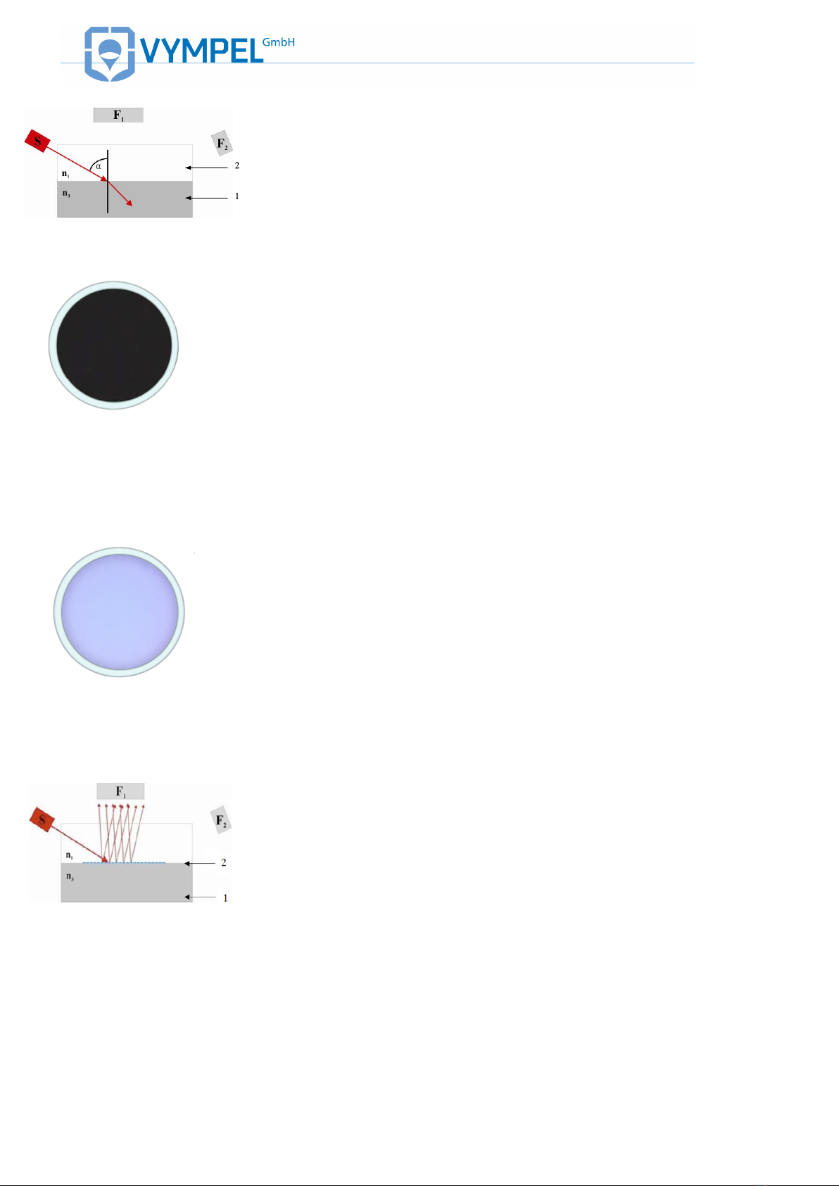
When the dew point mirror (dielectric surface) is clean, in other
words, when no condensate has formed, the polarized light rays
falling on the interface between the gas and the mirror’s surface
are completely refracted. As a result no light is reflected onto ei-
ther of the photo detectors (F1 and F2). This results in a null sig-
nal from the sensors (ILLUSTRATION 1). With the microscope
attached, total refraction can be observed visually under both side
lighting and vertical lighting. Under side lighting*, the surface of
the dielectric mirror appears black (illustration 2). Under micro-
scope (vertical) lighting the mirror’s surface appears light blue
(ILLUSTRATION 3).
*Please note: the side-lighting unit and the laser are not the same
component.
In the case of water vapor, as the temperature of the mirror is
lowered and condensation droplets begin to form, the angle at
which the polarized light strikes the surface changes with the re-
sult that refraction no longer occurs. Instead, the light rays are
reflected and scattered. The photoelectric registration system re-
cords an increase in the intensity of the light detected by the
photo detector located in position F1(ILLUSTRATION 4). The
signal intensity (aka signal level) is dependent on the amount of
water condensation.
Under side lighting, water condensation appears in the form of an
accumulation of luminous, somewhat similarly sized red droplets

!
!"#$"%&'&()*+,-./.,#&01&'&234567899::;3<&
**!
=11>?@34@=AB& & RD&S&H,#KF#/"E.,#&"/&/FF#&
$#KF+&/.KF&%.*LE.#*&
=11>?@34@=AB& & TD&S&H,#KF#/"E.,#&"/&/FF#&
$#KF+&-F+E.H"%&%.*LE.#*&
=11>?@34@=AB& & ;D&1.*LE&+")&K.GG+"HE.,#&"#K&
+FG%FHE.,#&K$F&E,&(I&H,#KF#/"E.,#&
=11>?@34@=AB& & 8D&(I&H,#KF#/"E.,#&O.#H%$KU
.#*&LFNE"#F/P&
in the middle of the mirror’s surface (ILLUSTRATION 5). Under
vertical lighting this condensation appears as an accumulation of
little round black spots evenly distributed over the entire surface
of the condensation mirror (ILLUSTRATION 6).
In the case of hydrocarbons, precipitated condensates accumu-
late in the form of a thin film on the surface of the mirror (Illustra-
tion 7). The building of a contiguous condensate layer (2) on the
mirrors surface (1) results in a change in the angle at which the
polarized light strikes the surface of the dielectric mirror.
The beam of light emitted by the laser is partially reflected as it
encounters the gas/condensate interface (3/2). This set of light
rays is then registered by the photo detector at position F2.
At the same time, due to the condensate film’s high degree of
transparency, a set of slightly refracted light rays, passes through
the gas/condensate interface and is reflected as it strikes the
condensate/mirror interface (2/1). These light rays are then also
registered by the photo detector at position F2. This second set of
rays is now slightly out of phase with the first set.
As a result, the registration system records two distinct light sig-
nals detected by the F2sensor. These two light signals create an
interference pattern due to the slight phase difference.
The intensity of the light signal detected by the sensor is directly
dependent on the quantity of hydrocarbon condensates in the
condensation film.
The hydrocarbon condensation process can only be observed
visually under vertical illumination. In contrast to water vapor con-
densation, the process of HC condensation cannot be made visi-
ble under side lighting, so even though the sidelight is activated,
the mirror remains dark (ILLUSTRATION 2).
Hydrocarbons up to and including Heptanes form rainbow colored
spots. These spread out until they link up to form one continuous
thin iridescent film. (ILLUSTRATION 8). If the mirror continues
to be cooled further, this thin iridescent film becomes a colorless
plastic layer covering the entire condensation mirror’s surface.
Octane and heavier hydrocarbons condense onto the mirror in
the form of small dark semi-transparent dots. With further cooling,
these dots grow to become small droplets and spots
(ILLUSTRATION 9).
Continuation of the cooling process causes these small droplets
to continue to grow, eventually forming large colorless drops of
condensate on an iridescent background.
For further images of water and hydrocarbon condensation refer
to Appendix N.

!
!"#$"%&'&()*+,-./.,#&01&'&234567899::;3<&
*"!
=11>?@34@=AB& & VD&(I&H,#KF#/"E.,#&O,HE"#F&
"#K&LF"-.F+P&
1.4. ANALYZER CONSTRUCTION
The analyzer’s cold-body housing (see ILLUSTRATION 10 and
ILLUSTRATION 11) consists of the high-pressure chamber (1)
a sample sized receptacle (hereafter in the text the measurement
cell (2)) a removable visualization system with 40 power magnifi-
cation (hereafter in the text microscope (16) and an electronic
module with an integrated touch screen display (10). The ana-
lyzer’s high-pressure chamber is designed for a working pressure
of up to 300 bar, and serves to supply and remove the sample
gas that passes over the condensation mirror. In order to observe
the condensation process, the high-pressure chamber is fitted
with a small window upon which the visualization system can be
mounted.
The microscope is mounted directly onto the Hygrovision’s high-
pressure chamber.
The electronic module controls the analyzer’s processes (cool-
ing/heating); records the mirror temperature and regulates the
photoelectric registration system.
The Hygrovision BL is operated by means of control buttons and
the touch screen display.
Recorded dew point values can be downloaded by means of an
IR port and an RS 485 interface.
In order for the analyzer to operate independent of an external
power supply, a slot for a storage battery is integrated into the
Hygrovision‘s housing, as is a socket for connecting the unit to an
external power supply (12–32V, 15W).
=11>?@34@=AB& & C:D&!".#&H,JN,#F#E/&,G&ELF& &
()*+,-./.,#&01&OCP&
Main components
(see ILLUSTRATION 10 and ILLUSTRATION 11)
•Gas delivery block (Pos.1);
•Measurement cell (PIP) (Pos.2);
•Battery compartment cap (Pos.3);
•Connection for the pressure sensor (Pos.4);
•Plug connector for the light emitting diode (Pos.5);
•RS 485 Modbus interface (Pos.6);
•Ventilation channel for supplementary cooling (Pos.7);
•IR port (Pos.8);
•On/off button (Pos.9)
•Touch screen (Pos.10);
•Control buttons (Pos.11);
•Sample gas inlet nozzle (Pos.12);
•Sample gas outlet nozzle (Pos.13);
•Stylus for use with the touch screen (Pos.14);
•Battery cap securing device (Pos.15).

!
!"#$"%&'&()*+,-./.,#&01&'&234567899::;3<&
*#!
=11>?@34@=AB& & CCD&!".#&H,JN,#F#E/&,G&ELF& &
()*+,-./.,#&01&O6P&
The measurement cell, the electronic module with integrated touch
screen and the power supply module (storage battery) are en-
closed within the analyzer’s metal housing (see Appendix A). The
housing is made up of three chambers.
Two of the three chambers (chambers 1 and 2) are pressure resis-
tant encapsulations. These chambers house the circuit boards for
the electronic module (chamber 1) and the storage battery (cham-
ber 2). The connection points for the external power supply and the
IR data port are located on the side of chamber 1.
The third chamber (chamber 3) houses all of the electronic mod-
ule’s control and display elements. The touch screen display is in-
tegrated into the top of chamber 3. Connection points for an exter-
nal pressure sensor and the microscope’s side-lighting element are
located on the side of this chamber. All of the electrical circuits
housed in chamber three meet the requirements for intrinsic safety.
BATTERY PACK
=11>?@34@=AB& & C6D&3FHL"+*F"W%F&W"EEF+)&
N"HX&
1.5. ANALYZER POWER SUPPLY
Hygrovision series analyzers have an independent onboard power
supply, the BP-06 power supply unit (hereinafter also referred to as
the rechargeable battery, battery, BP)
Important technical data for the BP:
Battery type
LIR18650 (Li-Ion);
Number of elements
6
Rated voltage
11.1 V
Max. discharge current
≤3 А
Electrical capacity
4 Аh
Service life
300 recharging cycles
(max. 2 years)
Operating conditions
-20 °C –+ 60 °С
Ladegerät
!
!
A detailed description of the BP unit’s operating requirements can
be found in the manual (KRAY5.549.006 ET) (included in delivery).
It is strongly recommended that only the (KRAY4.841.082) connec-
tion cable be used to connect the Hygrovision BL to an external
power source (12 –32V DC). This cable is designed specifically for
this purpose (ILLUSTRATION 13).
Refer to ILLUSTRATION 35 when connecting the analyzer to an
external power supply.
The Hygrovision’s battery pack should only be recharged using the
specially designed battery charger (KRAY5.122.007) included with
delivery. Information about the use of the charger can be found on

!
!"#$"%&'&()*+,-./.,#&01&'&234567899::;3<&
*$!
!
!
=11>?@34@=AB& & CMD&0"EEF+)&HL"+*F+&
O"HHF//,+)P
the label (KRAY5.122.007ET).
1.6. ADDITIONAL COMPONENTS AND
ACCESSORIES
Additional components include those systems and accessories that
ensure the optimal performance of desired analyzer functions.
Additional components fall into one of two categories:
•Additional components included as part of the Hygrovision
BL’s standard equipment;
•Additional components supplied at the customer’s request.
Standard equipment
Included with delivery as standard equipment:
•Microscope (KRAY3.821.003);
•Gas flow and gas pressure control system Model 001
(VMPL5.183.001);
•Gas delivery system Model 001
(VMPL6.450.001)Model -001 VMPL6.450.001;
•Filter for the control of glycols and heavy
hydrocarbons;
•Accessories used for the installation and maintenance
of the measuring system and for individual analyzer
modules.

!
!"#$"%&'&()*+,-./.,#&01&'&234567899::;3<&
*%!
MICROSCOPE
!
=11>?@34@=AB& & C9D&!.H+,/H,NF&
ILLUSTRATION 14 is an exterior view of the microscope
(KRAY3.821.003).
The optical system is positioned immediately above the high-pressure
chamber. Equipped with 40X magnification, this system makes it pos-
sible to directly monitor processes taking place on the mirror’s surface
inside the measurement chamber to visually evaluate the composi-
tional quality of the gas (see also 1.3).
The microscope is mounted onto the analyzer by way of a threaded
coupling integrated into the housing for this purpose.
Important components:
•Eyepiece (Pos.1);
•Electrical socket for the lighting system LED (Pos.2);
•Focusing ring (Pos.3)
Gas flow / gas pressure
control system (Model
001)
!
=11>?@34@=AB& & CRD&Y"/&G%,Q&"#K&
*"/&N+F//$+F&H,#E+,%&/)/EFJ&
The gas flow / gas pressure control system Model 001
(VMPL5.183.001) (ILLUSTRATION 15) displays information about
the operating pressure within the analyzer’s measurement chamber.
This system also provides a means to not only adjust the pressure
but also regulate the gas flow rate during the measurement process
(0.5 –1NL/min).
Included in delivery of the gas flow / gas pressure control system are:
•Manometer (Pos.1);
•Float flow meter with metal housing (Pos.2);
•Flow rate fine adjustment valve (Pos.3);
•Mounting and connecting elements
Refer to Appendix C for a mounting diagram of the gas flow and gas
pressure control system.
Please note:
Most of the systems and system modules are attached to the analyzer by
means of quick-coupling connectors. The advantage such connectors provide is
that no tools or special skills are needed for the installation of various modules
and installation can be accomplished in the shortest mount of time.

!
!"#$"%&'&()*+,-./.,#&01&'&234567899::;3<&
*&!
GAS DELIVERY SYSTEM
MODEL 001
!
=11>?@34@=AB& & CTD&Y"/&KF%.-F+)&/)/EFJ&
The gas delivery system provides a hermitically sealed
connection between the analyzer and the sample extraction
site. In addition, this system makes it possible to evenly
regulate delivery of the sample gas to the Hygrovision’s
measurement chamber.
Included in delivery of the gas delivery system are:
•Flexible high pressure hose (Pos.1;
ILLUSTRATION 16);
•Fine control valve (Pos.2; ILLUSTRATION 16)
Refer to Appendix D for gas delivery system assembly
instructions..
Please note:
The fittings included in delivery make it possible to connect the ana-
lyzer with various measurement equipment, devices, and systems in
the shortest amount of time and do not require additional tools or spe-
cialized skills.
PARTICLE FILTER
!
=11>?@34@=AB& & C;D&Z,/.E.,#&,G&ELF&N"+E.H%F&G.%EF+&
The analyzer is also equipped with an integrated particle filter
in order to remove solid particulates and other mechanical
contaminates from the sample gas. This filter (FE73A-15) is
positioned in the inlet side of the gas delivery housing (Pos.
1; ILLUSTRATION 17) and protects the condensation mir-
ror from possible damage from solid particulates and con-
taminates in the gas mixture.
The particle filter is included with delivery of the analyzer and
is preinstalled in the analyzer’s housing prior to initial deliv-
ery.
A replacement filter cartridge is included with the additional
components delivered with the analyzer as standard equip-
ment.
Please note:
There is a replacement filter cartridge included with the analyzer as
standard equipment. Additional replacement cartridges can be ordered
from Vympel at any time.
GLYCOLS AND HEAVY
HYDROCARBONS FILTER
When taking measurements to determine the dew point of
water, it is common for a variety of gas mixtures to have high
levels of glycol and heavy hydrocarbons. A specially de-
signed filter (KRAY6.451.017) is used for the taking of meas-
urements under these conditions. This filter is included as a
standard additional component with the Hygrovision BL.
(ILLUSTRATION 18).
The filter is installed directly in front of the fine control valve

!
!"#$"%&'&()*+,-./.,#&01&'&234567899::;3<&
*'!
!
=11>?@34@=AB& & C8D&Y%)H,%/&"#K&LF"-)&(I&G.%EF+&
at the end of the flexible high-pressure hose of the gas deliv-
ery system (VMPL6.450.001).
In terms of active filtering, the average service life of the filter
cartridge is eight hours. Therefore, the replacement interval
depends in large measure on the type and composition of
heavy hydrocarbons.
Usage requirements as well as detailed information about the
filter can be found in the manual (KRAY6.451.017ET), which
is included with delivery.
The glycol and heavy hydrocarbon filter is delivered with the
analyzer as standard equipment.
EXTERNAL POWER SUPPLY CABLE
!
=11>?@34@=AB& & CVD&Z,QF+&/$NN%)&H"W%F&
The external power supply cable (Illustration 20) is included
with the analyzer as standard equipment. It serves not only to
provide the device with electricity but also to transmit meas-
urement data by way of the RS 485 interface using the stan-
dard Modbus/RTU protocol.
Please refer to Table 5for instructions concerning electrical
configuration and connection..
IR ADAPTER
!
=11>?@34@=AB& & 6:D&=3&4K"NEF+&
The analyzer’s integrated infrared (IR) port can be connected
to a computer by means of the IR adaptor (KRAY5.999.005).
The position of the IR port is shown in Pos.8;
ILLUSTRATION 11.
Additional components that are available for order as optional
accessories include:
•Supplemental cooling system VMPL5.880.003;
•Tripod (Libec TH-650DV);
•Sample extraction system KRAY4.078.091(-01);
•Pressure reduction system VMPL2.848.005;
•High-pressure outflow module VMPL4.078.025;
•For a detailed list of the Hygrovision BL’s standard
and optional components, please refer to Table 3,
Point 1.12.

!
!"#$"%&'&()*+,-./.,#&01&'&234567899::;3<&
*(!
SUPPLEMENTAL COOLING SYSTEM
!
=11>?@34@=AB& & 6CD&?$NN%FJF#E"%&H,,%.#*& &
/)/EFJ&
The supplemental cooling system (VMPL5.880.003) should
be used when measuring dew point values below -30°C at
ambient temperatures above +30°C and at pressures over
100 bar (ILLUSTRATION 21).
The cooling system consists of a container filled with carbon
dioxide, two connector fittings, and a regulator valve to con-
trol the flow of refrigerant.
The system is connected to the outlet nozzle of the venting
channel (Pos.7; ILLUSTRATION 11).
Please refer to Appendix E for mounting instructions.
For a detailed description of the supplemental cooling system
please refer to “Special considerations when measuring dew
point at very low temperatures ”
TRIPOD
In order to make operating the analyzer more convenient
when in the field, the Hygrovision can be mounted on a Libec
TH-650DV tripod.
A tripod attachment point is integrated into the underside of
the Hygrovision’s housing. When mounted, the analyzer can
be oriented in the desired position.
SAMPLE GAS EXTRACTION SYSTEM
The optional sample extraction system (KRAY4.078.091 or
KRAY4.078.091-01) can be installed to create a stationary
sample gas extraction site. The system set consists of the
sample extraction apparatus (or a bypass valve) and a mem-
brane filter for the removal of liquids and particulates from the
gas sample.
Information regarding mounting and operating this system as
well as ordering replacement filter elements can be found in
the manual delivered with the set (KRАY4.078.091EТor
KRAY4.078.091-01ET).

!
!"#$"%&'&()*+,-./.,#&01&'&234567899::;3<&
*)!
PRESSURE REDUCTION SYSTEM
=11>?@34@=AB& & 66&
The pressure reduction system (VMPL2.848.005) provides
for the reduction of the sample gas pressure from the work-
ing pressure (max. inflow pressure is 250 bar) to a pressure
within the range 0.30 –35 bar.
The module includes a heating element to pre-warm the gas
sample in order to prevent premature condensation due to
the Joule-Thomson effect (a drop in temperature that is a
consequence of a drop in pressure in the gas mixture).
ILLUSTRATION 22 shows an overall view of the Pressure
Reduction System (PRS). For a schematic drawing, please
refer to Appendix F.
Detailed mounting and operating information can be found in
the manual (VYMP2.848.005RE) delivered with the PRS.
HIGH-PRESSURE
VENTING MODULE
The venting module (VMPL4.078.025) is used to channel the
sample gases flowing out of the Hygrovision’s measurement
chamber into the main venting line, in those situations where
the Hygrovision is used as a reference analyzer (Appendix
G).
GAS PREPARATION SYSTEM
SGA-003
!
=11>?@34@=AB& & 6MD&?Y4&::M&.#H%7&()*+,-./.,#&01&
The SGA 003 gas preparation system, or simply SGA,
(ILLUSTRATION 23) provides for the removal of various
aerosol and mechanical contaminants from the sample gas at
a working pressure of up to 160 bar.
The SGA is designed to accommodate the optional use of a
Hygrovision BL as a temporary reference analyzer. To that
end, a foldout mounting arm, and supplemental sample gas
connection points are integrated into the SGA’s construction.
In addition, the SGA is also fitted with a supplemental access
point on the explosion-proof terminal box in order to connect
the Hygrovision BL to an external power supply and link it to
the data transfer system.

!
!"#$"%&'&()*+,-./.,#&01&'&234567899::;3<&
"+!
1.7. CONTROL AND DISPLAY ELEMENTS
The analyzer has the following control elements:
On / off button (Pos.9; ILLUSTRATION 11);
Control buttons (Pоs.11; ILLUSTRATION 11) for regulating
the temperature of the condensation mirror.
The touch screen display (Pos.10; ILLUSTRATION 11) is
used to set and adjust the analyzer’s operating parameters.
The display presents information in the form of text and
graphics.
The touch screen stylus can be used to operate the display
(Pos. 14; ILLUSTRATION 10).
1.8. THE ANALYZER’S MENU
TURNING ON THE ANALYZER
=11>?@34@=AB& & 69&
To turn on the Hygrovision BL press and hold the on/off but-
ton for several seconds (Illustration 24).
After the analyzer has been switched on, the touchscreen
will display the software version information for two to three
seconds. (Illustration 25)
The BL is ready to begin measurement operations when the
software message is no longer displayed. The analyzer will
automatically revert to the operation at which it was set
when turned off (Illustration 26, 27).
The following control “icons” are displayed on the analyzer’s
screen:
!
=11>?@34@=AB& & 6R&
!
=11>?@34@=AB& & 6T&
!
=11>?@34@=AB& & 6;&
Table of contents
Other Vympel Measuring Instrument manuals
Popular Measuring Instrument manuals by other brands

SCRAM Systems
SCRAM Systems SCRAM CAM Quick reference guide

Polanik
Polanik WG15-SONIC instruction manual

Siemens
Siemens ASZ36 Mounting instructions

Rohde & Schwarz
Rohde & Schwarz VOR/ILS Analyzer EVS200 user manual

Topcon
Topcon GREEN LABEL GTS-250 Series instruction manual

Mgl
Mgl KPS-TLP100 instruction manual