W'eau WFI-007 User manual

Installation & Operation Manual
Swimming Pool Heat Pump
Model No.: WFI-007/010/013/017/021
Thank you very much for purchasing our product,please keep and read this manual carefully before
you install heat pump.


- 1 -
Fluorinated greenhouse gas – (R32)
The device contains the fluorinated greenhouse gas (R32) which is required for the device to work.
Industrial designation HFC-32
Common designation R32
Global warming potential (GWP) 675
Further information can be found on the device itself or the Specifications.
WARNING!
Risk of fire and explosion through leaking finned heat exchanger!
The refrigerant circuit of the finned heat exchanger contains highly pressurised, easily flammable,
odourless gas. Risk of fire and explosion in the event of uncontrolled gas leakage.
- Action of filling gas must be conducted by professional with R32 operating license.
- Keep the heat pump away from heat sources and naked flames.
- Do not drill into or scorch the heat pump.
- Do not use any objects apart from those permitted by the manufacturer to speed up the defrosting
process.
- Immediately shut off the heat pump if you suspect a gas leakage.
- The refrigerant is odourless. Always keep ignition sources away from the installation site of the heat
pump.
- Contact an authorized expert if you suspect a gas leakage.
WARNING!
Risk of electric shock!
A faulty electrical installation or a mains voltage that is too high can lead to electric shock.
- Have the installation, initial start-up and maintenance of the heat pump carried out by authorized
technician only.
- Please always cut the power supply if you want to open the cabinet to reach inside the heat pump
as there is high voltage electricity inside.
- Only start work on the heat pump after checking all safety regulations.
- Only connect the heat pump if the mains voltage from the power socket matches the voltage
indicated on the rating plate.
- Do not operate the heat pump if there is visible damage or the mains cable or the mains plug is
defective.
- Do not open the housing. Leave repairs to qualified specialists. Liability and warranty claims are

- 2 -
excluded in the event of repairs carried out on your own, improper operation.
- Ensure that children do not insert any objects into the fan blade and heat pump.
- Ensure that the electrical system to which the heat pump is connected has an earth conductor.
- If the unit would be installed where is vulnerable to lightning stroke, lightning protection
measurements must be carried out.
ATTENTION!
- The manufacturer declines any responsibility for the damage caused with the people,objects and of
the errors due to the installation that disobey the manual guideline. Any use that is without
conformity at the origin of its manufacturing will be regarded as dangerous.
- Please always keep the heat pump in the ventilation place and away from anything which could
cause fire.
- Don’t weld the pipe if there is refrigerant inside machine. Please keep the machine out of the
confined space when make gas filling by the authorized technician.
- Please always empty the water in heat pump during winter time or when the ambient temperature
drops below 0℃, or else the Titanium exchanger will be damaged because of being frozen, in such
case, it will be out of warranty for this machine.
- Please well keep the display controller in a dry area to protect the display controller from being
damaged by humidity.
Content
Accessories description............................................................................3
Attention for safety..................................................................................4
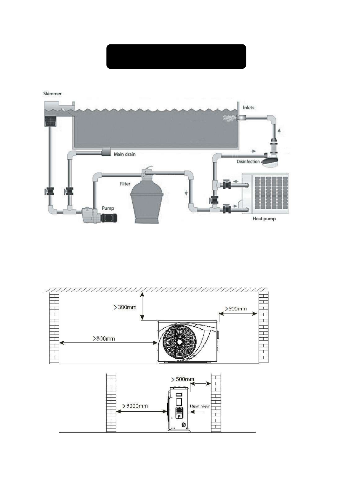
Installation of the unit.............................................................................5
Specifications..........................................................................................9
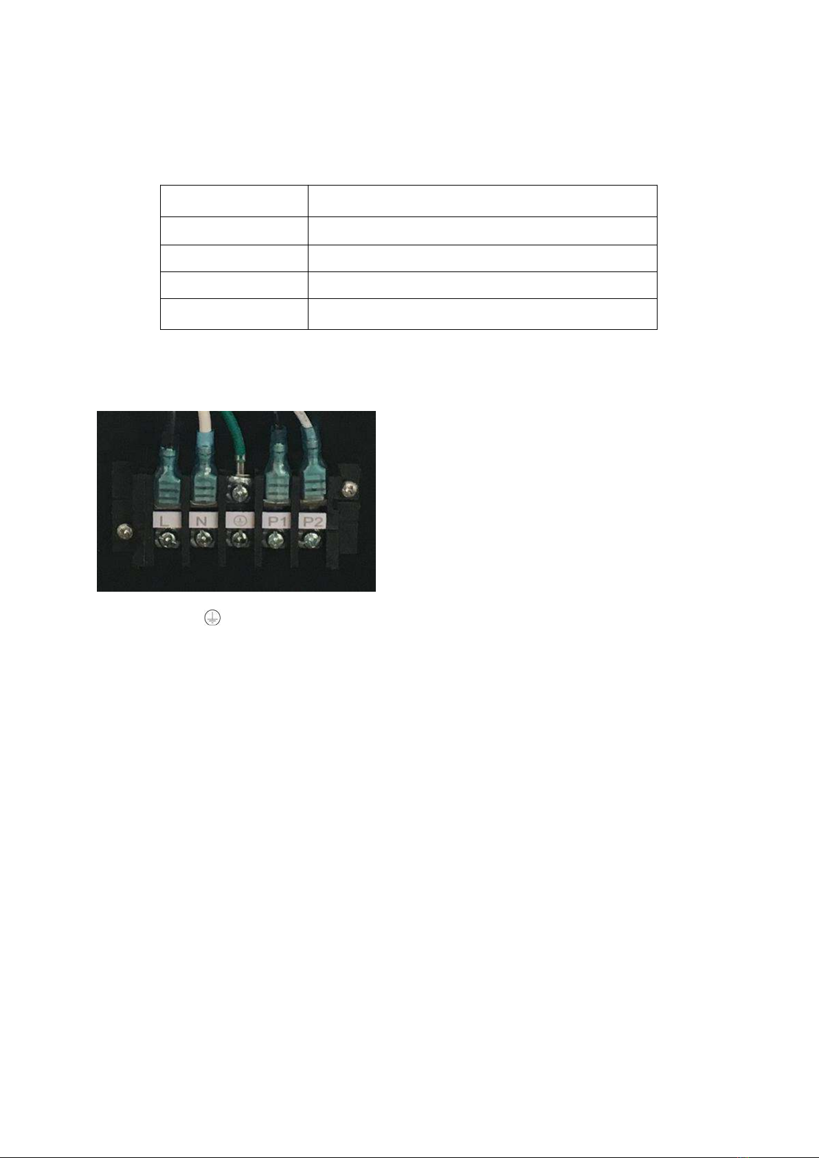
Electrical Wiring.....................................................................................10
Instruction of operation ........................................................................12
Adjusting and Initial operation...............................................................18
Operation and maintenance..................................................................19
Error codes & Solutions...................................................................... ...21
WiFi-Function........................................................................................23

- 3 -
1. Accessories description
Each unit produced by our factory is with the following accessories:
For function you need to purchase at least the following parts for each unit:
NOTE
The types and quantity of the water pipes, valves, filter equipment, sterilizing equipment which used for
the swimming pool heating/circulation pipe system, depend on the project design.
We suggest not to install auxiliary electric heaters in the system. If must install auxiliary electric heaters,
it should be operated by the specialized persons, and our company has no responsibility for all the
problem cause by the auxiliary electric heater.
Illustrations of machine
No.
Name
Qty.
Use
1
Instruction Manual
1 PC
Guide users to install the system
2
Drain-pipe
1 PC
Used for draining the condensate water
3
Drain-pipe connector
1 PC
Connect the drain pipe to the heat pump unit
4
Rubber shock absorber
4 PCS
Reduce vibration and reduce noise
5
Heat pump unit
1 SET
For heating water
6
Water connection
2 SET
Connect the piping system
No.
Name
Qty.
use
1
Water pump
1
Cycle the heated water
2
Filter system
1
Protect the heat pump from pool water
3
Water pipes system
1
Connect the equipment and make circulation

- 4 -
2. Attention for safety
Range of application:
1.Power supply: 220~240V/1N~50/60Hz.
2.Environment temperature: -15°C〜43°C
3.Water temperature range: 8°C~40°C in Heating function
8°C~28°C in Cooling function
●Confirm the ground connection, if the ground connection is not correctly done, it may cause
electric shock. And please cut off the power in the lightning storm weather.
●If install the heat pump in a small room, it must keep good ventilation.
●The main power switch should be out of the reach of Children.
●Don't put finger or stick into the air inlet or air outlet as the high-speed rotor may cause injury.
●When an exception happened (burning smell etc..), turn off the manual power switch immediately
and contact with after-sale service department.
●When the unit needs to be removed or re-installed or repaired, please entrust after-sale service
department and specialized personnel to do it. If the installation/ maintainence is not well done, it
may cause unit operation failure, electric shock, fire, hurt, leaking, etc.
●Must not be unauthorized reformed, otherwise it may cause electric shock or fire.
●Must not install the unit with combustible around.
●Confirm the installation base is strong enough to avoid falling of the heat pump.
●Confirm leakage protection switch is installed to avoid electric shock or other issues.
●When cleaning the unit, the operation should be stopped, and power switch should be turned off.

- 5 -
3. Installation of the unit
3.1 Installation Illustration
Above illustration is just for the reference, please take the advice of authorized installers.
3.2 Advised installation space
Keep the following indicated space for operation and maintenance when make the installation.

- 6 -
3.3 Additional By-pass kits
The additional By-pass kits is suggested to be put into the piping system to get the better adjustment
of water flow.
3.4 Heat pump unit size
A
B
C
D
E
F
G
H
I
J
K
WFI-007/010
591
836
379
335
98
640
98
107
290
26
11
WFI-013/017/021
641
896
389
363
128
640
128
107
340
26
11

- 7 -
3.5 Heat pump Exploded View
No.
Parts
No.
Parts
1
Fan protective gill
15
Water flow switch
2
Front panel
16
Titanium heat exchanger
3
Fan blade
17
Right structure
4
Fan motor
18
Manometer
5
Left panel
19
Right panel
6
Left structure
20
Control panel
7
Evaporator
21
Electrical terminal cover
8
Fan motor mount
22
Electrical terminal block
9
Upper structure
23
Electrical cable support
10
Electric box cover
24
Electronic expansion valve
11
Electrical box
25
Reactive resistance
12
Top cover
26
Bottom panel
13
Plastic net
27
Four-way valve
14
Middle panel
28
Compressor

- 8 -
3.6 Electrical connection
*Suggested power cable specification
Model
Power Cable Specification
WFI-007/010
3*1.5 mm²
WFI-013/017
3*2.5 mm²
WFI-021
3*4 mm²
Terminal
Terminal cable max. 4 mm²
*Electrical connection
Position L,N and is for the power connection of our heat pump.
Position P1 and P2 is for the Single phase water pump.

- 9 -
4. Specifications
4.1 Specifications
Model No.
WFI-007
WFI-010
WFI-013
WFI-017
WFI-021
* Heating Capacity at Air 26℃, Humidity 80%, Water 26℃
Heating Capacity (kW)
7.6~1.7
10.5~2.3
13.5~3.0
17~3.8
21.1~4.8
Power Input (kW)
1.12~0.11
1.54~0.15
1.99~0.19
2.50~0.24
3.10~0.30
COP
15.8~6.8
15.8~6.8
16~6.8
15.8~6.8
15.8~6.8
* Heating Capacity at Air 15℃, Humidity 70%, Water 26℃
Heating Capacity (kW)
5.8~1.3
7.8~1.7
10~2.2
12.7~2.8
15.8~3.5
Power Input (kW)
1.18~0.17
1.59~0.22
2.0~0.29
2.59~0.37
3.22~0.46
COP
7.6~4.9
7.6~4.9
7.6~5
7.6~4.9
7.6~4.9
* Cooling Capacity at Air 35℃, Water 29℃in, 27℃out
Cooling Capacity (kW)
4.3~1.0
5.9~1.4
7.2~1.8
9.4~2.3
11.4~2.8
Power Input (kW)
1.13~0.15
1.55~0.21
1.89~0.27
2.47~0.34
3.0~0.42
EER
6.6~3.8
6.7~3.8
6.7~3.8
6.7~3.8
6.7~3.8
* General data
Power supply
220~240V/1/50~60Hz
Rated Power Input (kW)
1.18
1.59
2.0
2.59
3.22
Rated Current (A)
5.36
7.23
9.09
11.77
14.64
Water Flow Volume (m3/h)
2.5
3.5
4.5
5.5
6.5
Advised pool size m3
10~25
15~50
18~62
25~85
55~120
Compressor/ Type
Mitsubishi/ Rotary
Refrigerant
R32
Heat Exchanger
Screwed titanium tube
Water connection (mm)
50
Fan motor
Brushless DC type
Defrosting function
Automatic/ Manual
Water temp. range under heating (℃)
8~40
Water temp. range under cooling (℃)
8~28
Working temp. range (℃)
-15~43
Casing Material
ABS
Water Proof Level
IPX4
Noise level dB(A) 10m
20~28
20~29
22~31
22~34
22~35
Noise level dB(A) 1m
38~48
39~49
42~51
43~54
43~55
Net Weight (kg)
42
43
53
54
58
Gross Weight (kg)
53
54
64
65
69
Net Dimensions (mm)
836*379*591
896*389*641
Package Dimensions (mm)
930*400*650
990*435*750
* Above data are subjects to modification without notice.

- 10 -
5. Electrical wiring
5.1 Electric wiring diagram
WFI-007/010

- 11 -
WFI-013/017/021

- 12 -
6.Instruction of operation
6.1 Wire controller (Function of buttons)
6.2 Definition of display

- 13 -
6.3 Start up & Locking
Press the button to switch the heat pump on or off. This button is also used to return to the
main interface.
When the heat pump is in operation, hold the button for 3 seconds to lock or unlock the
controller. (The lock is activated automatically after 60 seconds of inactivity). When the display is
locked, the logo appears.
* Please unlock the controller before the other operations every time.
Attention:Before you start, make sure the filtration pump is running and that water is
flowing through the heat pump.
6.4 Operation Mode Selected

- 14 -
Hold the button for 3 seconds to change the below four operating modes each time:
:Mode ECO Inverter: Choose this heating mode that the heat pump operates silently.
:Mode Boost Inverter: Choose this heating mode that the heat pump operates
powerfully.
:Mode Cooling Inverter:Choose this cooling mode that the heat pump intelligently cools the
water of your pool.
:Mode Auto: The heat pump can switch Heating and Cooling function automatically
6.5 Set the required temp.
On the main interface, press and to adjust the desired water temp. of your pool, then
press the to save the setting.
When setting the water temp., the icon ‘SET’will light on, the left one is Setting temp., the right one
is the Outlet water temp.
After finished the setting, the icon ‘SET’will extinguish, the left one will become Inlet water temp.,
the right one Outlet water temp.

- 15 -
6.6 Clock setting
Press the button to enter the clock setting interface. Clock display on right bottom flashes.
Change the hours using and , then press again to go to minute setting, change the
minutes using the and .
Press again to confirm the setting and return to the main menu.
6.7 Timer setting
Hold the button for 3 seconds to enter the setting of Timer ON & Timer Off groups.
1
ON
OFF
2
3
will flash, then set the Turn On and Off timer like the Clock setting.
Pay attention: There are 3 groups Timer for your every day setting.
You can press to save the current setting and go back to the main interface.
Cancel the Timer: Hold the button for 3 seconds to cancel all the timer setting.
6.8 Definition of other icons
: Defrosting :Compressor : 4-way valve

- 16 -
A
Fan Speed : Signal of Water pump : Wi-Fi function
Attention:With the indication of the functions or key parts, it is helpful for service
team to maintain or repair the heat pump.
6.9 Manual defrosting
Hold and for 3 seconds to start Manual defrosting function.
6.10 Factory setting recovery
Hold and and and for 5 seconds to recover factory setting.
6.11 Running Parameter checking
Press to enter the Running parameters checking, then press and to check the
below parameters as below:
N°
Description
Unit
C01
Ambient temperature
°C
C02
Evaporator coil temperature
°C
C03
Exhaust temperature
°C
C04
Return temperature
°C
C05
Reserved
°C

- 17 -
C06
Reserved
°C
C07
Titanium heat exchanger temperature
°C
C08
Water inlet temperature
°C
C09
Water outlet temperature
°C
C10
Reserved
C11
Reserved
C12
Reserved
C13
Temperature sensor failure
C14
Refrigerant system failure
C15
Inverter driver failure
C16
Device output
C17
Running status
C18
AC voltage
V
C19
DC voltage
V
C20
Actual frequency
Hz
C21
EEV open degree
C22
Reserved
C23
Heat pump current
A
C24
Compressor current
A
C25
DC fan motor1 speed
Rpm
C26
Compressor target frequency
Hz
C27
DC fan motor2 speed
Rpm
C28
Control system software version
C29
Driver software version
C30
Controller software version

- 18 -
7.Adjusting and Initial operation
7.1 Attention
● Open the valve of water system, inject water into the system, and exhaust air inside.
● Do adjustment after electrical safety inspection.
● After the power is switched on, start the test running of heat pump, to check if it can function well.
● To avoid dangerous accident, the forced operation is forbidden.
7.2 Preparation Before Adjustment
● The system is installed correctly.
● Tubes and lines are putted in the right place.
● Accessories are installed.
● Ensure the smooth drainage.
● Ensure the perfect insulation.
● Correct connection of ground lead.
● The supply voltage can meet the requirement of rated voltage.
● Air inlet and outlet function can work well.
● Electrical leakage protector can work well.
7.3 Adjustment Process
● Check if the switch of the controller can work well.
● Check if the function keys of the controller can work well.
● Check if the drainage system can work well.
● Check if the system can work well after starting up.
● Check if the water outlet temperature is in correct situation.
● Check if there is vibration or abnormal sound when the system is functioning.
● Check if the wind, noise and condensate water produced by the system affect the environment
around.
● Check if there is refrigerant leakage.
● If any Error codes occur, please check the instructions for the detailed info.
This manual suits for next models
12
Table of contents
Other W'eau Heat Pump manuals
Popular Heat Pump manuals by other brands

Cosmic
Cosmic ACDC12 User and installation guide

Gorenje
Gorenje TC100ZW Instructions for use

Hisense
Hisense AHW-100HCDS1 installation manual

HTW
HTW VAX Owners and installation manual

Robur
Robur K18 Simplygas Installation, use and maintenance manual

Lennox
Lennox VEP Series Installation & operation instructions