W2IHY iBOX User manual

-12-
AUDIO OUT CABLE WIRING
TEN TEC
DRAKE TR7
DRAKE T4XB
COLLINS 32S 1, 32S3
COLLINS KWM2A
COLLINS 32V2, 32V3
Hallicrafters
E.F. Johnson
HI-Z
HI-Z
Yaesu
FT101E
Galaxy
Kenwood
TS520/TS530
TS820/TS830
+ Audio
+ Audio
+ Audio
+ Audio
- Audio
- Audio
- Audio
- Audio
- Audio
+ Audio
+ Audio
- Audio
PTT
PTT
PTT
PTT
PTT
PTT
GND
GND
GND
GND
GND
GND
4 Pin Mic Connector Pin 3
4 Pin Mic Connector Pin 2
4 Pin Mic Connector Pin 3
4 Pin Mic Connector Pin 2
4 Pin Mic Connector Pin 3
4 Pin Mic Connector Pin 1
4 Pin Mic Connector Pin 3
4 Pin Mic Connector Pin 1
2 Pin Mic Connector Pin 1
2 Pin Mic Connector Pin 2
2 Pin Mic Connector Spring/Case
4 Pin Mic Connector Pin 2
4 Pin Mic Connector Pin 1
4 Pin Mic Connector Pin 4
Attenuator Audio Out to Xcvr cable wiring
Shield of Cable
Shield of Cable
Shield of Cable
Shield of Cable
Shield of Cable
Shield of Cable
DIN connectors shown on the side to be soldered
DO NOT SOLDER TO SHIELD OF DIN OPERATING MANUAL
VARIABLE ATTENUATOR
AND
INTERFACE BOX
iBox

-2-
VARIABLE ATTENUATOR
AND
INTERFACE BOX
OPERATING MANUAL
April 2003
Julius D. Jones
19 Vanessa Lane
Staatsburg, N.Y. (12580)
(845) 889-4253
E-mail: Julius@W2IHY.COM
Home Page: http:// www.w2ihy.com
c 2003 W2IHY, ALL RIGHTS RESERVED
TECHNOLOGIES
W2IHY
iBox
-11-
AUDIO OUTPUT CABLE WIRING
Alinco DX77
Kenwood
TS130/140
TS430/440
TS850/TS870
TS930/940/950
SG2020
K2
Japan Radio
JST-135
JST-245
Yaesu
FT990/ft992
FT1000MP/M-V
+ Audio
PTT
GND
ICOM
735
745/746
756/756 PRO
775
781
KACHINA
Gnd
PTT
+ Audio
Gnd
Gnd
PTT
PTT
- Audio
- Audio
- Audio
- Audio
+ Audio
+ Audio
8 Pin Mic Connector Pin 8
8 Pin Mic Connector Pin 5
8 Pin Mic Connector Pin 3
8 Pin Mic Connector Pin 1
8 Pin Mic Connector Pin 7
8 Pin Mic Connector Pin 5
8 Pin Mic Connector Pin 6
Shield of Cable
Shield of Cable
Shield of Cable
Shield of Cable
8 Pin Mic Connector Pin 2
8 Pin Mic Connector Pin 6
8 Pin Mic Connector Pin 7
8 Pin Mic Connector Pin 1
8 Pin Mic Connector Pin 8
Yaesu
FT102
FT747/757/767
FT847
FT1000/1000D
+ Audio
PTT
GND
- Audio
8 Pin Mic Connector Pin 6
8 Pin Mic Connector Pin 7
Shield of Cable
8 Pin Mic Connector Pin 8
ICOM BALANCED
MODULATOR
746
756 / 756 PRO
775
781
910H
+ Audio
PTT
GND
- Audio
8 Pin DIN Connector Pin 3
8 Pin DIN Connector Pin 2
Shield of Cable
8 Pin DIN Connector Pin 4
DIN connectors shown on the side to be soldered
DO NOT SOLDER TO SHIELD OF DIN
Attenuator Audio Out to Xcvr cable wiring

-10-
AUDIO OUTPUT CABLE WIRING
HI-Z
Attenuator Audio Out Wiring
LOW Z TRS BALANCED OUTPUT
LOW Z UNBALNCED 1/4”
MONO CONNECTOR
LOW Z Single channel Input
to Computer Sound Card
HI Z TRS BALANCED OUTPUT
LOW-Z
LOW-Z
LOW-Z
HI-Z
LOW-Z
- Audio
- Audio
- Audio
- Audio
+ Audio
+ Audio
+ Audio
+ Audio
GND
GND
GND
GND
Shield of Cable
Shield of Cable
Shield of Cable
Shield of Cable
LOW Z XLR BALANCED OUTPUT
HI-Z XLR BALANCED OUTPUT
- Audio
- Audio
+ Audio
+ HI-Z Audio
GND
GND
Shield of Cable
Shield of Cable
1
2
3
1
2
3
-3-
INTRODUCTION
iBox by W2IHY
iBox is a variable audio attenuator designed to
be a versatile accessory for the serious amateur.
iBox can be used to not only provide the proper
audio levels and impedance matching between
pieces of equipment in your audio chain or to your
amateur radio equipment but it may also be used to
eliminate ground loops that usually show up in the
form of hum. iBox can also be used to provide RF
isolation between components. iBox achieves its
outstanding isolation through use of a high quality
audio transformer and filter networks. iBox’s input
impedance is 600 ohms. The output impedance of the
iBox may be selected to be either 600 ohms or 50K
ohms. This means the iBox can be connected to
modern and vintage radio equipment as well as
between audio rack components.
iBox was designed at the request of amateurs who
were using studio audio equipment and needed a
more versatile way to level match, RF isolate, audio
isolate, PTT control and impedance match audio and
transmitting components..
We feel so confident that you will be delighted with the
iBox we offer a 30 day money back , no questions
asked, guarantee. The iBox represents affordable
audio technology designed for amateur radio use.

-4-
iBox CONTROLS
1
2
(1) Output Level Control (R2)
This potentiometer (pot.) adjusts
the audio output of the iBox .
Turning the pot. fully counter -
clockwise will obtain a signal at
the Audio Output about 48dB less than the input signal.
Turning the pot. clockwise will increase the signal level to
the Audio Output.
(2) Audio Input (J1)
This 1/4” stereo jack (also known
as a Tip-Ring-Sleeve jack) is
used to bring audio into the iBox.
See page 8 for additional cable wiring information.
<== Audio Plug from Source to Attenuator ==>
AUDIO CONFIGURATION TIP RING Sleeve
Source: Balanced Output
Wire Input Plug: Balanced Input + MIC - MIC Ground
Source: Balanced Output
Wire Input Plug: Unbalanced Input + MIC - MIC and Ground - MIC and Ground
Source: Unbalance Output
Wire Input Plug: Unbalanced Input + MIC Ground Ground
TIP
RING
SLEEVE
-9-
AUDIO INPUT CABLE WIRING
Attenuator Audio Input Wiring
LOW Z TRS BALANCED Output
(from source)
LOW Z COMPUTER OR OTHER
SINGLE STEREO CHANNEL
OUTPUT TO ATTENUATOR
LOW-Z
LOW-Z
LOW-Z
- Audio
+ Audio
+ Audio
GND
Shield of Cable
Shield of Cable
LOW Z XLR OUTPUT
(from source)
- Audio
+ Audio
Shield of Cable
1
2
3
LOW-Z UNBALANCED OUTPUT
(from source) LOW-Z
+ Audio
GND Shield of Cable

-5-
iBox CONTROLS
3
4
(3) PTT Input (J3)
This female RCA connector is
used to provide push to talk
control (PTT). Grounding the
center jack of the connector grounds
the PTT line of the Audio Out connector.
(4) Audio Output (J2)
This 5 pin DIN connector provides
attenuated Input audio to the
connector. The audio provided
is isolated from the input audio.
The user may wire cables for either LOW-Z (600 ohms)
or HI-Z (50K) balanced or unbalanced. PTT function is
also provided at this connector
Gnd
PTT
- Mic
+ Mic Balanced
Output
Hi-Z Output
Audio Output
5 Pin Male DIN
Din connectors shown
on side to be soldered
-8-
Value of R2 in “K” ohms
Value of R2 in “K” ohms Value of R2 in “K” ohms
ATTENUATION OF AUDIO INPUT AS
R2 CHANGES WHERE R3=200 Ohms
MILLIVOLTS OF AUDIO OUTPUT AS
R2 CHANGES WHERE R3=200 Ohms
AND 1 VOLT OF AUDIO IS APPLIED
TO THE INPUT
MILLIVOLTS OF AUDIO OUTPUT AS
R2 CHANGES WHERE R3=0 Ohms
AND 1 VOLT OF AUDIO IS APPLIED
TO THE INPUT
ATTENUATION OF AUDIO INPUT AS
R2 CHANGES WHERE R3=0 Ohms
Attenuation in dB
Millivolt Output
Millivolt Output
Attenuation in dB
Figure 3A
Figure 3B
Figure 3C
Figure 3D
C2
.001 uf
C2
.001 uf
GndGnd
E3
C4
.001 uf
C4
.001 uf
C6
.001 uf
C6
.001 uf
RFC1
470 uh
RF choke
RFC1
470 uh
RF choke
RFC3-470 uh RF chokeRFC3-470 uh RF choke
RFC2
470 uh
RF choke
RFC2
470 uh
RF choke
RFC4
470 uh RF choke
RFC4
470 uh RF choke
C1
.001 uf
C1
.001 uf
C3
.001 uf
C3
.001 uf
C5
.001 uf
C5
.001 uf
600:600600:600
+ Audio Out+ Audio Out
+ Audio in+ Audio in
- Audio in- Audio in
- Audio Out- Audio Out
GndGnd
R1-1KR1-1K
R2
10K or 100K
fixed or variable
R2
10K or 100K
fixed or variable
R3
200
R3
200
R2R2
R4
1K
R4
1K
T1
1:1
++
C7
100 uf
C7
100 uf
E1
E2
E4
E5 E9
E8
E7
E6
iBox LOW-Z AUDIO OUT
RESPONSE CHARACTERISTICS
Note:
R2 Pot factory installed at 100K ohms
R3 factory installed at 200 ohms
Figure 2
Figure 4
0
20
40
60
025 50 75 100
0
20
40
60
025 50 75 100
0
200
400
600
025 50 75 100
0
200
400
600
800
025 50 75 100
Assumes 600 ohm load on attenua tor output
R1 R2 R3 R4
Att enuation*
R2=0 to R2=
Max
Impedance
to radio
R2=0 to
R2=Max
Impedance
on Xfmr
"T1" R2=0
to R2=
Max
1000 100000 200 1000 '-6.2 to -48.4 dB 336 to 990 384 to 994
1000 100000 0 1000 -3.2 to -48.4 dB 275 to 990 293 to 994

-7-
C2
.001 uf
C2
.001 uf
C4
.001 uf
C4
.001 uf
C6
.001 uf
C6
.001 uf
RFC1
470 uh
RF choke
RFC1
470 uh
RF choke
RFC3-470 uh RF chokeRFC3-470 uh RF choke
RFC2
470 uh
RF choke
RFC2
470 uh
RF choke
RFC4
470 uh RF choke
RFC4
470 uh RF choke
C1
.001 uf
C1
.001 uf
C3
.001 uf
C3
.001 uf
C5
.001 uf
C5
.001 uf
600:600600:600
+ Audio Out+ Audio Out
+ Audio in+ Audio in
- Audio in- Audio in
- Audio Out- Audio Out
GndGnd
GndGnd
R1-1KR1-1K
R2
10K or 100K
fixed or variable
R2
10K or 100K
fixed or variable
R3
200
R3
200
R2R2
R4
1K
R4
1K
T1
1:1
++
C7
100 uf
C7
100 uf
E1
E2
E3
E4
E5 E9
E8
E7
E6
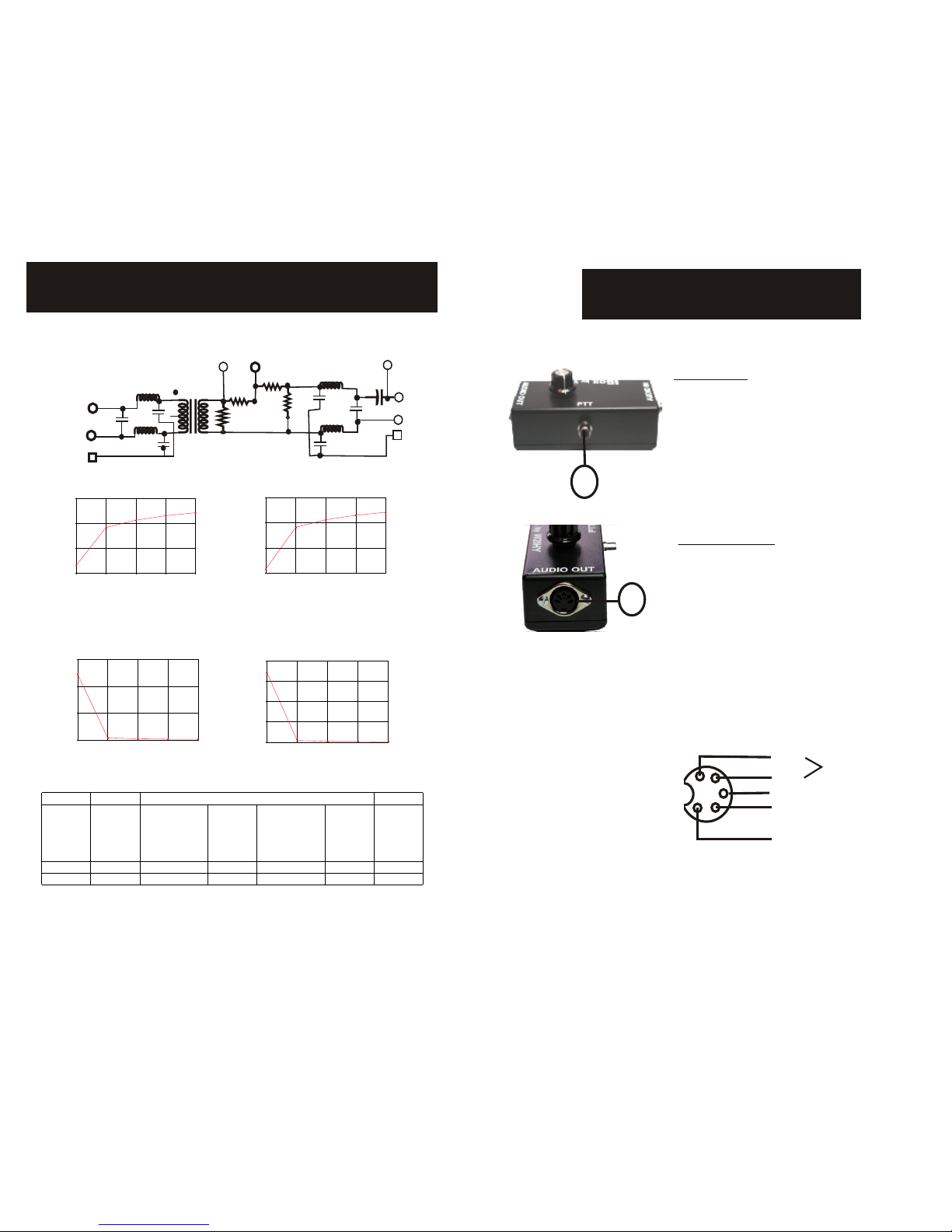
iBox SCHEMATIC AND WIRING PICTORIAL
C8
.1 uf
Shield
Shield
Red
Red
Red
Black
Black
Black
Shield
C9
.1 uf
47K ohm
J2
5 pin DIN connector
J1
(TRS connector) J3
(RCA connector)
Audio Out
Audio IN
Gnd tab R2=
100K
factory
wired
4”
4”
3”
--------------------Parts List------------------
C1-C6 - .001 uf mylar
C7 - 100 uf radial electrolytic
C8,C9 - .1 uf monolithic ceramic capacitors
J1- 1/4” stereo jack
J2 - 5 Pin DIN
J3 RCA panel mounted jack
R3 - 200 ohm ¼ watt 5% resistor
R1,R4 - 1K ohm ¼ watt 5% resistor
R2 - fixed resistor or variable potentiometer
R5- 47K ¼ watt 5% resistor
RFC1 - RFC4 - 470 uh miniature r.f. Choke
T1 - 1:1 600 ohm Audio Transformer
Figure 1C
Figure 1B
Figure 1A
-6-
QUICK START TUTORIAL
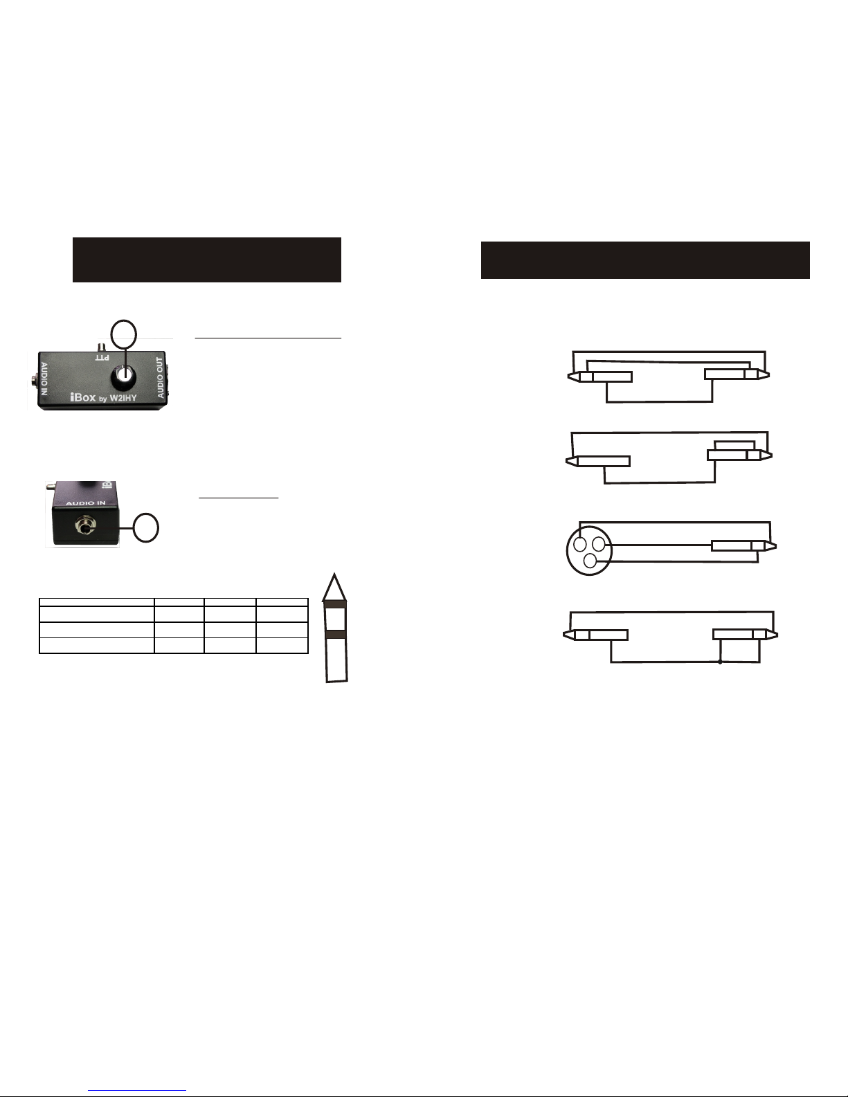
1. Turn the Output Level Control fully counter clockwise. (See page 4)
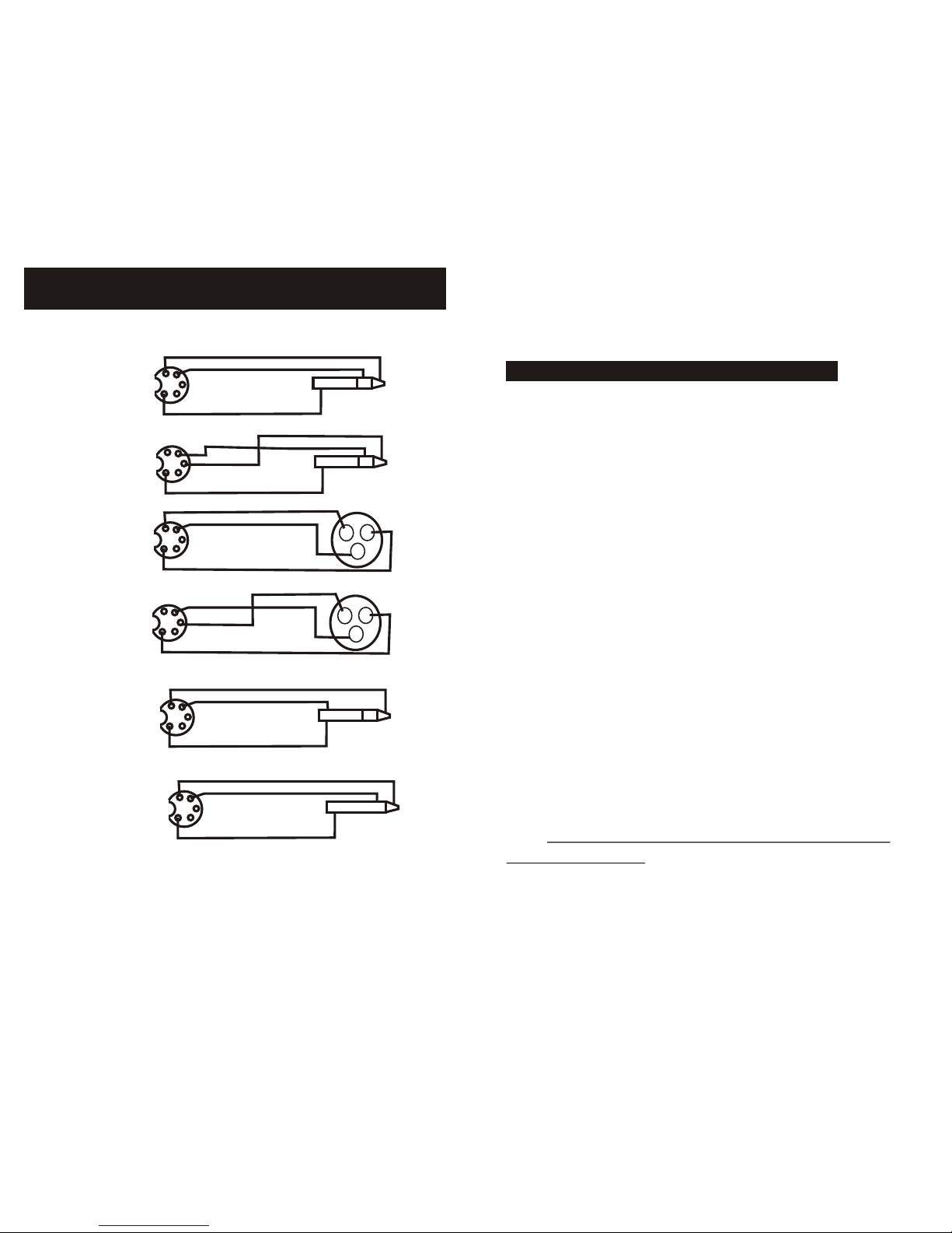
2. Connect the audio source into the Audio Input jack (see page 4)
using a 1/4” stereo plug. Page 9 shows some possible cable config-
urations. Make sure the sleeve of the 1/4” stereo plug is connected
to the ground of the audio source.
3. Connect the Audio Output (see page 5) to what you would
like to drive. See pages 10-12 for possible cabling configurations.
Make sure that the ground pin on the DIN connector is
connected to the ground of what is being driven.
4. If you will be using a foot switch to key a transmitter or other
device connect it to the PTT RCA connector (see page 5).
5. Prior to applying an audio signal to the input of the iBox turn the
Output Level Control fully counter clockwise. (See page 4).
6. Apply an audio signal to the input of the iBox, Turn the Output
Level Control clockwise until proper audio level for the device
being driven is obtained.
Minimizing the effects of RF
A very common problem many amateur radio operators experience
with professional audio equipment while transmitting is audio distortion
caused by RF. Techniques have been developed to minimize the effects
of RF. In a perfect world one should use a star grounding configuration,
using heavy gauge braided wire from grounded equipment to the
central ground point and a short run of a heavy gauge wire to a
ground rod. In a perfect world all audio equipment should be
connected to a high quality power conditioner. In a perfect world
all audio cabling should use quality shielded wire (double shielded
is best). In a perfect world all audio signals cascading through the
audio rack network should be isolated with high quality audio
transformers. Few of us live in a perfect world so when we have
problems we have to make the RF environment we live in as good
as possible.
AUDIO
IN
PTT
AUDIO
OUT
Audio
Source
Radio
or
Audio
Component
Foot
Switch
iBox
J1
J2
J3
V
V
V
Table of contents