WACKER Group DPU 25..H.. User manual

www.wackergroup.com
Operator´s Manual
Vibratory plate
DPU 25..H..
0109976en 002
10.2007


T00940GB.fm 3
Important information
This machine has been provided with an EPA-certified engine.
Additional information can be found in the engine
manufacturer‘s notes.
Engine exhaust, some of its constitvents, and certain vehicle
components contain or emit chemicals known to the State of
California to cause cancer and birth defects or other reproduc-
tive harm.
WARNING
Caution
This engine is an EPA engine.
Adjusting the engine speed will interfere with EPA certification and
the emissions.
Only authorized personnel can make adjustments to this engine.
Please contact you nearest engine dealer or your Wacker Dealer for more
information.

T00940GB.fm 4

Vorwort.fm 5
Foreword
1. Foreword
For your own safety and protection from bodily injuries, carefully read,
understand and follow the safety instructions in this manual.
Please operate and maintain your Wacker machine in accordance with
the instructions in this manual. Your Wacker machine will reward your
attention by giving trouble-free operation and a high degree of
availability.
Replace faulty or defective components Immediately.
All rights, especially the right for copying and distribution are reserved
Copyright 2007 by Wacker Construction Equipment AG
No part of this publication may be reproduced in any form or by any
means, electronic or mechanical, including photocopying, without
express permission in writing from Wacker Construction Equipment AG.
Any type or manner of reproduction, distribution or storage on data
carriers or storage mediums not authorized by Wacker represents an
infringement of valid copyrights and will be prosecuted. We expressly
reserve the right to make technical modifications - even without due
notice - which aim at improving our machines or increasing their safety
standards.

Table Of Contents
6
1. Foreword 5
2. Safety instruction 8
2.1 General instructions ..............................................................................8
2.2 Operation ...............................................................................................8
2.3 Safety checks ......................................................................................10
2.4 Maintenance ........................................................................................10
2.5 Transport .............................................................................................11
2.6 Maintenance checks ............................................................................11
3. Technical Data 12
4. Description 14
4.1 Applications .........................................................................................14
4.2 Dimensions ..........................................................................................14
4.3 Max. admissible inclination ..................................................................15
4.4 Description of function .........................................................................15
5. Transport to work site /Recommendations on compaction 17
5.1 Transport to work site ..........................................................................17
5.2 Recommendations on compaction ......................................................18
6. Operating instructions 19
6.1 Diesel fuel ............................................................................................19
6.2 Dry-type air filter ..................................................................................19
6.3 Air cleaner – inspecting the service indicator ......................................20
6.4 Starting the engine ..............................................................................20
6.5 Switching off the engine ......................................................................21
6.6 Short-term operation interruption ........................................................21
6.7 End of compaction operation ...............................................................21
7. Maintenance 22
7.1 Maintenance schedule ........................................................................22
7.2 Engine oil .............................................................................................23
7.3 Hydraulic control ..................................................................................25
7.4 Exciter .................................................................................................26
7.5 Exciter V-belt .......................................................................................27

Table Of Contents
7
8. Malfunction 28
8.1 Reverse speed too low ........................................................................28
8.2 Forward speed too low ........................................................................28
8.3 No advance .........................................................................................28
8.4 Loss of hydraulic oil .............................................................................28
8.5 Engine does not start ..........................................................................29
8.6 No vibration, even though engine is running .......................................29
9. Lables 30
EC - Conformity Certificate 31
DIN EN ISO 9001 Certificate 33

Safety instruction
SV00069GB.fm 8
2. Safety instruction
for the use of vibratory plates with combustion engines
2.1 General instructions
2.1.1 Vibratory plates may only be operated by persons who
∗are at least 18 years of age
∗are physically and mentally fit for this job
∗have been instructed in guiding vibratory plates and proved their ability
for the job to the employer
∗may be expected to carry out the job they are charged with carefully.
The persons must be assigned the job of guiding vibratory plates by
the employer.
2.1.2 Vibratory plates may only be used for compaction jobs. Both the
manufacturer’s operating instructions and these safety instructions
have to be observed.
2.1.3 The persons charged with the operation of vibratory plates have to be
made familiar with the necessary safety measures relating to the
machine. In case of extraordinary uses the employer shall give the
necessary additional instructions.
2.1.4 This machine generates noise that exceeds the country-specific
permissible noise levels (individual rating level). It may therefore be
necessary to wear ear protection
2.2 Operation
2.2.1 Only use original spare parts. Modifications to this machine, including
the adjustment of the maximum engine speed set by the manufacturer,
are subject to the express approval of Wacker. In case of
nonobservance all liabilities shall be refused.
2.2.2 The function of operation levers or elements is not to be influenced or
rendered ineffective.
2.2.3 During operation the operator may not leave the control elements.
2.2.4 The operator has to stop the engine of the vibratory plate before going
on breaks. The machine has to be placed such that it cannot turn over.

Safety instruction
SV00069GB.fm 9
2.2.5 Stop engine before filling fuel tank. When refilling fuel tank, do not
allow fuel to come into contact with the hot part of the engine or spill
onto the ground.
2.2.6 Do not smoke or handle open fire near this machine.
2.2.7 The tank lid must fit tightly. Shut fuel cock if available when stopping
the engine. For long distance transports of machines operated by fuel
or fuel- mixtures, the fuel tank has to be drained completely.
Leaky fuel tanks may cause explosions and must therefore be
replaced immediatelly.
2.2.8 Do not operate this machine in areas where explosions may occur.
2.2.9 Make sure that sufficient fresh air is available when operating vibratory
plates equipped with combustion engines in enclosed areas, tunnels,
galleries and deep trenches.
2.2.10 During operation keep your hands, feet and clothes away from the
moving parts of the vibraton plate. Wear safety shoes, and eye
protection glasses in case of trench operation where falling sand
stones maybe ejected.
2.2.11 When working near the edges of breaks, pits, slopes, trenches and
platforms, vibratory plates are to be operated such that there is no
danger of their turning over or dropping in.
2.2.12 Make sure the soil or subsoil to be compacted has a high enough load
carrying capacity.
2.2.13 Use appropriate protective clothing while working or while carrying out
maintenance work.
2.2.14 When traveling backwards the operator has to guide the vibration plate
laterally by its guide handle so that he will not be squeezed between
the handle and a possible obstacle. Special care is required when work
ing on uneven ground or when compacting coarse material. Make sure
of a firm stand when operating the machine under such conditons.
2.2.15 Vibratory plates are to be guided such that hand injuries caused by
solid objects are avoided.
2.2.16 Vibratory plates have to be guided such that their stability is
guaranteed.
2.2.17 Machines with integrated transport trolley may not be parked or stored
on the trolley. This device has only been designed to transport the
machine.

Safety instruction
SV00069GB.fm 10
2.3 Safety checks
2.3.1 Vibratory plates may only be operated with all safety devices installed.
2.3.2 Before starting operation, the operator has to check that all control and
safety devices function properly.
2.3.3 If defects in the safety equipment or other defects are detected which
impair the safe operation of the internal vibrator, the supervisor is to be
notified without delay.
2.3.4 The machine must to be switched off immediately in case of defects
jeopardizing the operational safety of the equipment.
2.3.5 Process materials and operating fuels must be stowed away in
receptacles or containers marked according to the respective
manufacturers specifications.
2.4 Maintenance
2.4.1 Only use original spare parts. Modifications to this machine including
the adjustment of the maximum speed set by the manufacturer are
subject to the express approval of WACKER. In case of
nonobservance all liabilities shall be refused.
2.4.2 All drive units have to be switched off before carrying out maintenance
jobs. Deviations from this are only allowed if the maintenance or jobs
require a running engine.
2.4.3 When working on vibratory plates equipped with electric starter,
disconnect battery before carrying out maintenance or repair jobs on
the electric parts of the machine.
2.4.4 Remove pressure from hydraulic lines before working on them.
Caution: take care when removing hydraulic lines, for the oil may be
very hot (up. over 80° C). Precautions are to be taken to prevent oil
from splashing into the operator’s eyes.
2.4.5 All safety devices must be reinstalled properly immediately after
maintenance and repair jobs have been completed.
2.4.6 Do not hose down the machine with water after each use to avoid
possible malfunctions. Do not use high pressure washers nor chemical
products.

Safety instruction
SV00069GB.fm 11
2.5 Transport
2.5.1 During transport, loading and unloading of vibration plates by means
of lifting devices, appropriate slinging means or hooks have to be used
on the lifting points provided for this purpose on the vibratory plate.
2.5.2 The load-carrying capacity of the loading ramps has to be sufficient
and the ramps have to be secure such that they cannot turn over. Make
sure that no one be endangered by machines turning over by slipping
or by moving machine parts.
2.5.3 When being transported on vehicles, precautions have to be taken that
vibration plates do not slip or turn over.
2.6 Maintenance checks
2.6.1 According to the conditions and frequency of use, vibratory plates have
to be checked for safe operation at least once a year by skilled
technicians, such as those found at WACKER-service depots and
have to be repaired if necessary.
Please also observe the corresponding rules and regulations valid in your
country.

Technical Data
TD00682GB.fm 12
3. Technical Data
DPU 2540H DPU 2550H DPU2560H DPU 2560H-TS
Item no. 0610035 0610036 0610037 0610038
Operating weight kg: 160 166 171
Advance and reverse travel
m/min: 24 22 20 23
Compacted area m2/h: 576 660 720 828
Kraftübertragung From drive engine directly to exciter unit via centrifugal
clutch and V-belt
Exciter
Vibrations min-1 (Hz): ca. 5400 (90)
Centrifugal force kN: 25
Oil Fuchs Titan Unic 10W40 MC (SAE 10W40)
Oil quantity l: 0,6
Drive motor Air-cooled single-cylinder 4-cycle diesel engine with recoil starter
Piston displacement cm3:232
Engine speed (rpm) min-1:2800
Rated power (*) kW (PS): 3,1 (4,2)
Fuel Diesel
Fuel consumption l/h: 0,4
Tank capacity l: 3,0
Oil Fuchs Titan Unic 10W40 MC (SAE 10W40)
Oil quantity l: 0,9
Hydraulic control
Hydraulic oil Fuchs Renolin MR 520
Oil quantity 0,4

Technical Data
TD00682GB.fm 13
(*) In accordance with the installed useful outlet power according to Directive 2000/14/
EG
Special lubricating
grase LPA:94 dB(A)
The weighted effec-
tive acceleration
value, determined
according to
EN ISO 5349
m/s2:is 8,8
DPU 2540H DPU 2550H DPU2560H DPU 2560H-TS
Description
T00978GB.fm 14
4. Description
4.1 Applications
This vibratory plate is optimally suited for all types of soil compaction
applications in confined areas thanks to it’s narrow design and the
infinitely variable change of direction; application examples are e.g.
compaction in cable trenches, marginal strip compaction during
asphalt pavement patchwork as well as all those compaction jobs for
which the use of larger machines is not convenient.
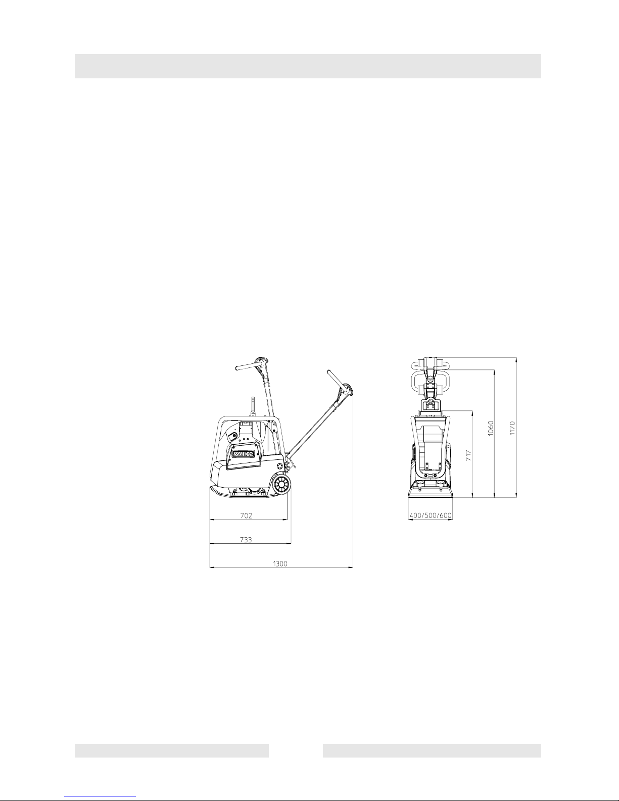
4.2 Dimensions

Description
T00978GB.fm 15
4.3 Max. admissible inclination
4.4 Description of function
4.4.1 The vibration required for compaction is produced by the exciter (5)
which is firmly joinded to the lower mass (4). This exciter (5) is
designed as a central vibrator with aligned vibrations. Such a principle
permits the direction of vibration to be changed by turning the eccentric
weights (13). In this way an infinitely variable transition between
vibration in forward motion, at standstill and in reverse motion is
possible.
This process is hydraulically controlled with the operating control
handle (7) on the centre pole head (8).

Description
T00978GB.fm 16
4.4.2 The drive engine (1) is anchored to the upper mass (3) and drives the
exciter (5). The torque is transmitted by means of a friction connection
through the centrifugal clutch (9) and the exciter V-belt (10).
4.4.3 The centrifugal clutch (9) interrupts flow of power to the exciter (5) at
low engine speeds and thus permits perfect idling of the drive engine
(1). The speed of the drive engine (1) can be infinitely varied by way of
the throttle lever (6).
4.4.4 The upper (3) and lower (4) masses are connected to each other by 4
vibration-damping shock mounts (11). This damping system prevents
the very high frequencies from being transmitted to the upper mass (3).
As a result the functionability of the drive engine (1) is retained in spite
of the high compaction performance.
4.4.5 The drive engine (1) works according to the diesel principle, is
equipped with a recoil starter, draws in combustion air through a dry
type air cleaner (12) and is air-cooled.
Forwards Reverse
On the spot

Transport to work site /Recom-
T00979GB.fm17
5. Transport to work site /Recommendations on
compaction
5.1 Transport to work site
Conditions:
∗To transport the vibration plate, use only suitable lifting equipment with
a minimum load-bearing capacity of 200 kg.
∗Only attach suitable tackle at the central lifting point (15) provided.
∗Always tie down the vibratory plate by the protective frame (14) and
latch the center pole in place during transport of the vibratory plate on
the loading area of a transport vehicle.
The engine must be stopped when using the integrated transport
device. Lubrication of the engine is not guaranteed if the engine is
running when the plate is in transport position.This could lead to
serious engine damages.
Furthermore the danger exists that oil will spill out of the crankcase
breather.
Note: Also observe the regulations in the chapter “Safety instructions“.
Transport to work site /Recommendations on compaction
T00979GB.fm18
5.2 Recommendations on compaction
5.2.1 Ground conditions
The max. compaction depth depends on several factors relating to the
ground condition, such as moisture, grain distribution etc,
it is therefore not possible to specify exact values.
Recommendation: In each case determine the max. compaction
depth with compaction tests and soil samples.
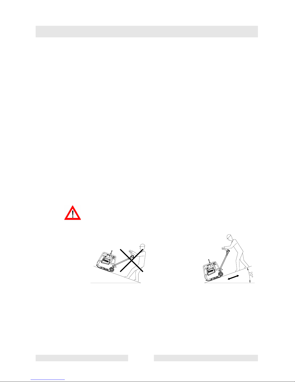
5.2.2 Compaction on slopes
The following points are to be observed when compacting on sloped
surfaces (slopes, embankments):
∗Only approach gradients from the bottom (a gradient which can be
easily overcome upwards, can also be compacted downwards without
any risk).
∗The operator must never stand in the direction of descent (see chapter
“safety instructions“).
∗The max. gradient of 20omust not be exceeded.
If this gradient were exceeded, this would result in a failure of the
engine lubrication system and thus inevitably lead to a breakdown of
important engine components.
Wrong! Right!

Operating instructions
T00980GB.fm 19
6. Operating instructions
6.1 Diesel fuel
Only use pure diesel fuel.Close fuel tank immediately. It is important to
maintain absolute cleanliness to avoid otherwise inevitable trouble
with the fuel injection system, and to avert a premature clogging up of
the fuel filter. Do not open the fuel line nor the fuel pump or any other
point of the fuel system to avoid danger of dirt contamination, not
even for bleeding of air. The fuel pump will bleed automatically. This
applies even should the fuel tank have run dry by mistake. In such a
case simply refill fuel tank.
6.2 Dry-type air filter
A loss of engine power with a simultaneous belching of smoke
indicates a plugged-up air filter. Remove filter cartridge and clean by
light tapping to dislodge dust from the paper element.
Clean filter housing! Use a clean rag, do not clean with compressed
air. While cleaning avoid by all means introducing dirt into the engine
intake port.

Operating instructions
T00980GB.fm 20
6.3 Air cleaner – inspecting the service indicator
Set the engine to full rpms for a short period of time. If the bellows is
drawn together during this time and the green field „1“ is covered, then
the air cleaner system is due for maintenance. Check the rubber
bellows repeatedly per day when working in dusty environments.
6.4 Starting the engine
∗Only start with the engine starting procedure once a sufficiently stable
position is assured.
∗Move throttle lever to start position.
∗Slowly pull out starter rope until the engine’s compression resistance
can be felt.
∗At this point let starter rope slowly return into starter housing.
∗Now start the engine. Pull out the rope (evenly, not by jerks as is usual
with gasoline engines) and turn the engine with ever increasing speed.
Use complete length of starter rope.
Table of contents
Other WACKER Group Power Tools manuals


