Wacker Neuson WL 750 User manual

Wheel loaders
WL 750
WL 850
OPERATOR'S MANUAL
1000184973 US 2.1
0909
www.wackerneuson.com
1000184973

BA 34603_04 US – Edition 2.1 * 34603_04b110.fm 1-1
Introduction
1 Introduction
1.1 Important information on this Operator's Manual
This Operator's Manual contains important information on how to work safely, correctly
andeconomicallywiththemachine.Therefore,itaimsnotonlyatnewoperators,butitalso
serves as a reference for experienced ones. It helps to avoid dangerous situations and
reduce repair costs and downtimes. Furthermore, the reliability and the service life of the
machine will be increased by following the instructions in the Operator's Manual. This is
why the Operator's Manual and the service booklet must always be kept at hand in
the machine.
Your own safety, as well as the safety of others, depends to a great extent on how the
machine is moved and operated. Therefore, carefully read and understand this Operator's
Manual before operating the machine for the first time. The Operator's Manual will help to
familiarize yourself more easily with the machine, thereby enabling you to use it more
safely and efficiently.
Before operating the machine, carefully read chapter “Safety Instructions” as well, in
order to be prepared for possibly hazardous situations. As a rule, keep the following in
mind:
Careful and prudent working is the best way to avoid accidents!
Operationalsafety andreadiness ofthe machinedo notonly dependon your skill,but also
on maintenance and servicing of the machine. This is why regular maintenance and ser-
vice work is absolutely necessary (see service booklet). Always have a technician with
appropriate training or an authorized service center perform the maintenance and repair
work which are not included in this Operator's Manual. Insist on using original spare parts
when performing maintenance and repair work. This ensures operational safety and readi-
ness of your machine, and maintains its value.
Your Wacker Neuson dealer will be pleased to answeranyfurther questions regarding the
machine or the Operator's Manual.
Abbreviations/symbols
☞This symbol requires you to perform the activity described
☞Subdivision within lists or an activity. Follow the steps in the recommended sequence
• This symbol stands for a list
• Subdivision within lists or an activity. Follow the steps in the recommended sequence
➥Description of the effects or results of an activity
“Option” = optional equipment
Stated whenever controls or other components of the machine are installed as an option.
Traveling direction in drawings or figures.
Introduction

1-2 BA34603_04US–Edition2.1*34603_04b110.fm
Introduction
1.2 Machine overview
Fig. 1: Machine outside views
Pos. Description
1Service flap (fuses, relays, recirculated air filter)
2Rearview mirror
3Handle
4Working lights
5Eye hook for removing the cab only
(may not be used for crane-lifting the machine.)
6Brake, rear and turn indicator lights
7Door arrester
8Towing facility
9Reflectors
10 Rear eye hook for loading/tying down the machine
11 Door handle
12 Headlight with turn indicator
13 Access
14 Wheel chock
15 Loader unit
16 Tilt cylinder
17 Front eye hook for loading/tying down the machine
18 Lift cylinder
Pos. Description
521 3 4
9
10
8
151617 111213
7
6
18
14

BA 34603_04 US – Edition 2.1 * 34603_04b110.fm 1-3
Introduction
1.3 Models and trade names: overview
1.4 Brief description of the wheel loader
The wheel loader is aself-propelled work machine according toGerman traffic regulations.
Get informed on and follow the legal regulations of your country.
This machine is a versatile and powerful tool for moving earth, gravel and debris on con-
struction sites and elsewhere.
The wide rangeof attachmentsaccounts for the numerousapplicationsofthe machine:as
a fork lift, a snow plow, a spreader for grit, salt etc., a sweeper or a tree replanter.
See chapter Attachments with certified material densities on page 1-5 for further applica-
tions. Retrofit the machine with appropriate safety features when using it in lifting gear
operation (see section “Applications with lifting gear” in chapter Safety Instructions).
The main components of the machine are:
• ROPS/FOPS tested closed cab
Check number: ROPS 04139-CE (cab without protective screen)
Check number: FOPS 04140-CE (cab with optional protective screen)
• Water-cooled Deutz four-cylinder in-line engine
• Exhaust emissions according to EC standard 2004/26 EC
• Rubber-mounted engine
• Sturdy steel sheet frame
• Automotive drive, infinitely variable hydrostatic axial-piston gearbox;
maximum speed 20 kph / 12.5 mph (30 kph / 18.8 mph option)
• Hydraulic four-wheel power steering with emergency steering features
• Front and rear planetary steering axles, rear axle with oscillation
• Service brake (mechanical and hydrostatic), mechanical disc-type parking brake
Wheel loader model Trade name
346-03 WL 750
346-04 WL 850

1-4 BA34603_04US–Edition2.1*34603_04b110.fm
Introduction
Hydrostatic drive
The diesel engine permanently drives a hydraulic pump (variable displacement pump),
whoseoil flowis sent to a hydraulic motor flanged on the gearbox. The forceof thehydrau-
licmotor is transmittedto therearaxle viathe transfer gearbox.At the sametime, thefront
axle is driven by the cardan shaft, ensuring permanent 4 wheel drive.
Work hydraulics and 4 wheel steering
The diesel engine also drives the joint gear pump for work hydraulics and hydrostatic 4
wheel steering. The oil flow of this pump depends on the diesel engine speed only.
Whenthemachineis in operation,theentirediesel engine output canbetransmitted to the
gear pump for work hydraulics and steering. This is made possible by an inching valve
whichrespondsassoon as theservicebrakeis used,reducingorcuttingoff power inputof
the drive. Therefore, engine output is fully available for the loader unit by pressing the
accelerator pedal and the brake pedal at the same time.
Cooling system
A combined oil/water radiator (for the diesel engine and the hydraulic oil) is located at the
rear of the machine.
The indicators on the instrument panel of the machine ensure constant monitoring of the
coolant temperature and level, and of the hydraulic oil temperature.

BA 34603_04 US – Edition 2.1 * 34603_04b110.fm 1-5
Introduction
1.5 Fields of application and using the wheel loader with an attachment
The attachments installed determine the intended use of this machine.
Note that not all attachments listed in the table comply with local traffic regulations.
The attachments complying with local traffic regulations and the applicable provisions are
listed in the machine documentation!
Thelegislationofyourcountrymayrequirespecific permits,certifications,registrationsetc.
fortheuse of attachmentsthat are notcertified or notlisted in the machinedocumentation!
Get informed on and follow the legal regulations of your country.
Important
To minimize the risk of equipment damage and unsafe operating characteris-
tics, the attachments listed below are the only attachments approved for use
with this wheel loader.
Attachments with certified material densities
Possible equipment and authorized material densities.
Description of
attachment
Wheel
loader
Part no.
(model) Dimensions Use
Standard bucket –
normal material
WL 750 1000102344
1000102345
10001606481
1750 mm (68.89”) with teeth
1750 mm (68.89”) without teeth
1750 mm (68.89”) without teeth Loosening, picking up, transporting and
loading loose or solid material
(material density ≤p = 1.8 t/m³)
(material density ≤p = 112 lbs./cu. ft.)
WL 850 1000096388
1000096389
1000137538
1850 mm (72.83”) with teeth
1850 mm (72.83”) without teeth
Standard bucket – light-
weight material2
WL 750 1000096389 1850 mm (72.83”) without teeth Picking up, transporting and loading very
lightweight material
(material density ≤p = 1.3 t/m³)
(material density ≤p= 81 lbs./cu. ft.)
WL 850 1000096393 2050 mm (80.70”) without teeth
Standard bucket – super-
lightweight material2
WL 750 1000096394
2150 mm (84.64”) without teeth
Picking up, transporting and loading light-
weight material
(material density ≤p = 0.9 t/m³)
(material density ≤ p = 56 lbs./cu. ft.)
WL 850 1000096397
Multipurpose bucket 3WL 750 1000113244
1000113492
1000168415
1750 mm (68.89”) with teeth
1750 mm (68.89”) without teeth
Grading, removing and scraping vegetation,
for example; picking up and evenly spread-
ingmaterial;grabbingbulkymaterial;loading
trucks (material density ≤p = 1.8 t/m³)
(material density ≤p = 112 lbs./cu. ft.)
WL 850 1000050770
1000096400 1850 mm (72.83”) with teeth
1850 mm (72.83”) without teeth
Side swing bucket2, 3 WL 750 1000175757 1744 mm (68.66”) without teeth As standard bucket, however with benefits
for filling and backfilling material
(material density ≤p = 1.8 t/m³)
(material density ≤p = 112 lbs./cu. ft.)
WL 850 1000176121 1844 mm (72.60”) without teeth

1-6 BA34603_04US–Edition2.1*34603_04b110.fm
Introduction
See“MerkblattfürAnbaugeräte“(leafletwithspecificinstructionsfor attachments)§30clauses10/11/12of theStVZOGermanroadtrafficregulationsforfurtherinformationonmountingattachments.
High-tilt bucket3, 4, 5 WL 750 1000156433
1000108803 1850 mm (72.83”) without teeth
1850 mm (72.83”) without teeth As standard bucket, with a 80 – 100 cm
higher dump height
(material density ≤p = 1.8 t/m³)
(material density ≤p = 112 lbs./cu. ft.)
WL 850 1000156433
1000154475 1850 mm (72.83”) without teeth
Heavy duty bucket with
hydraulic clamp3, 4, 5
WL 750 1000111090 1850 mm (72.83”) Picking up and transporting e.g. bulky recy-
cling material
(material density ≤p = 1.3 t/m³)
(material density ≤p= 81 lbs./cu. ft.)
WL 850 1000111053 2050 mm (80.70”)
Heavy duty forks with
hydraulic clamp
(silage bucket)3, 4 WL 750
WL 850 1000128262 1800 mm (70.86”)
Picking up and transporting e.g. bulky and
fibrous recycling material (e.g. grass,
manure, brushwood;
material density ≤p = 1.3 t/m³)
(material density ≤p= 81 lbs./cu. ft.)
Pallet forks3, 4, 6 WL 750
WL 850 1000101820
1000101822 1000 mm (39.37”)
1200 mm (47.24”) Picking up and transporting
pallets
Palletforks withfoldable fork
arms3, 6, 7 WL 850 1000147393 1200 mm (47.24”) Picking up and transporting
pallets
Material pusher3, 4 WL 750
WL 850 1000050660 3000 mm (118.11”) For moving loose bulk material
Manure forks with grab WL 750
WL 850 1000178474 1800 mm (70.86”) Picking up and transporting e.g. grass,
manure, brushwood and straw
Hydraulic round bale clamp WL 750
WL 850 1000177701 800 – 1800 mm
(31.49 – 70.86”) Picking up and transporting round bales
Tree replanter3, 4 WL 750
346-02 1000100840 – Digging and transporting nursery trees
Front scarifier3, 4 WL 750
WL 850 1000100841 – Scarifying dense soil, loosening humus soil
Work platform8WL 750
WL 850 1000109953 – For repair, assembly, disassembly, mainte-
nance and inspection work above ground
Rotary broom WL 750
WL 850 1000139717 – Cleaning roads or facilities
Snow plow2, 3, 4, 9WL 750
WL 850 1000142915 – Winter service
1. Bucket with screwed-on exchangeable blade
2. Only in connection with additional lights order no. 1000105002 and mounting kit order no. 1000137629 when traveling on public roads
3. See the Operator's Manual of the attachment for putting the attachment into service and using it
4. Not certified for traveling on public roads (individual certification may be possible depending on your country's legislation)
5. Only in connection with restrictor unit order no. 1000114139
6. Only in connection with load diagrams for model WL 750 (order no. 1000138363) and for model WL 850 (order no. 1000143064)
7. Get informed on the legal regulations of your country which may require specific permits, certifications, registrations etc. for use on public roads!
8. Model WL 750: only in connection with assembly 1000169659
Model WL 850: only in connection with assembly 1000169660
9. Only in connection with rotating beacon order no. 1000133985
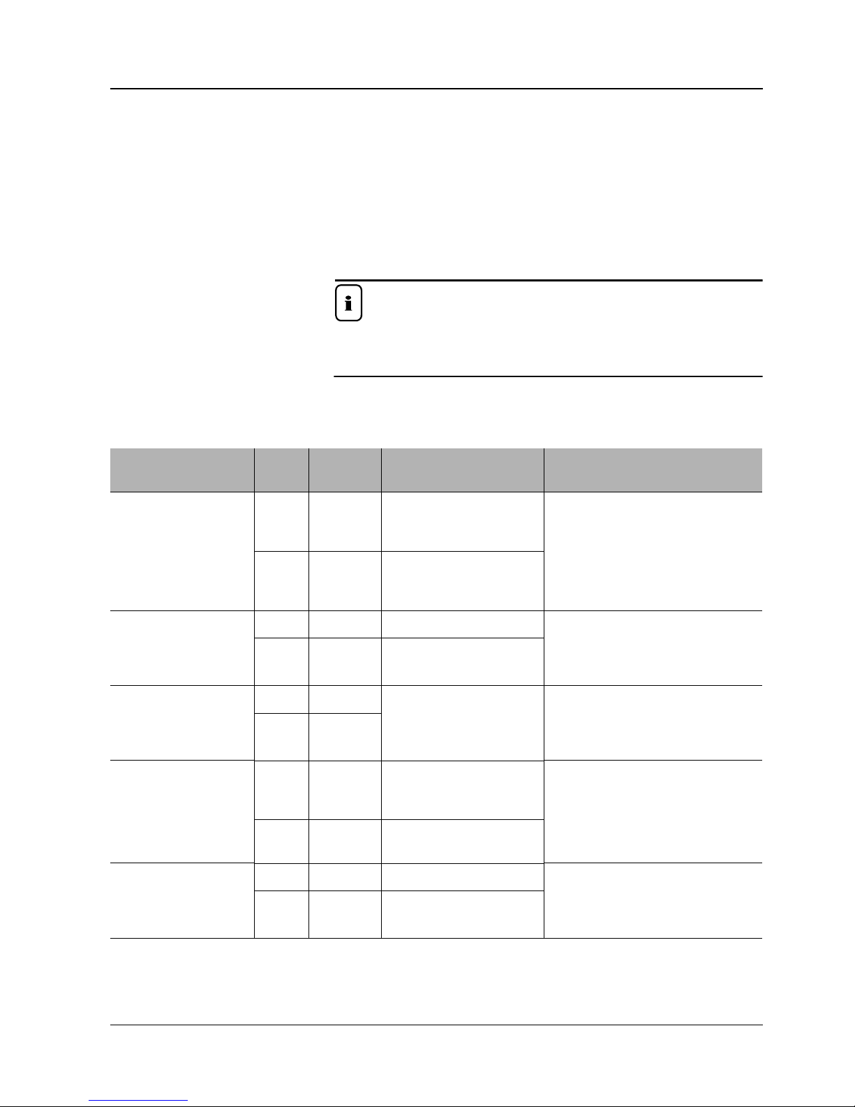
Description of
attachment
Wheel
loader
Part no.
(model) Dimensions Use

BA 34603_04 US – Edition 2.1 * 34603_04b110.fm 1-7
Introduction
1.6 EC declaration of conformity, model 346-03 (WL 750)
EC Declaration of Conformity
Manufacturer
Kramer-Werke GmbH
Wacker-Neuson-Str. 1
D-88630 Pfullendorf
Product
Conformity assessment procedure
According to 2000/14/EC, appendix VIII, by the following inspection body:
Fachausschuss Tiefbau, Prüf- und Zertifizierungsstelle
Landsberger Str. 309
D-80687 München
Directives and standards
We hereby declare that this product corresponds to the relevant regulations and
requirements of the following EC Directives and standards:
98/37/EC, 89/336/EEC, DIN EN ISO 12100-1, DIN EN ISO 12100-2, DIN EN 474-1,
DIN EN 474-3, ISO 3471, ISO 13510, EN ISO 3744, EN ISO 3746, ISO 3449
Pfullendorf, (date)
i. A.
Dipl.-Ing. Manfred Mack
Head of Research & Development
KRAMER-WERKE GmbH
Product Wheel Loader
Model 346
Version 346-03
Serial number 346 03 _ _ _ _ _
Output kW 45
Measured sound power level dB(A) 99.8
Guaranteed sound power level dB(A) 101

1-8 BA34603_04US–Edition2.1*34603_04b110.fm
Introduction
1.7 EC declaration of conformity, model 346-04 (WL 850)
EC Declaration of Conformity
Manufacturer
Kramer-Werke GmbH
Wacker-Neuson-Str. 1
D-88630 Pfullendorf
Product
Conformity assessment procedure
According to 2000/14/EC, appendix VIII, by the following inspection body:
Fachausschuss Tiefbau, Prüf- und Zertifizierungsstelle
Landsberger Str. 309
D-80687 München
Directives and standards
We hereby declare that this product corresponds to the relevant regulations and
requirements of the following EC Directives and standards:
98/37/EC, 89/336/EEC, DIN EN ISO 12100-1, DIN EN ISO 12100-2, DIN EN 474-1,
DIN EN 474-3, ISO 3471, ISO 13510, EN ISO 3744, EN ISO 3746, ISO 3449
Pfullendorf, (date)
i. A.
Dipl.-Ing. Manfred Mack
Head of Research & Development
KRAMER-WERKE GmbH
Product Wheel Loader
Model 346
Version 346-04
Serial number 346 04 _ _ _ _ _
Output kW 45
Measured sound power level dB(A) 99.8
Guaranteed sound power level dB(A) 101

BA 34603_04 US – Edition 2.1 * 34603_04b110.fm 1-9
Introduction
1.8 Type labels and component numbers
Serial number
The serial number is stamped on the machine frame A(nextto the cab attachment, on the
right in traveling direction). It is also located on the type label B(fig. 2).
ThetypelabelBislocatedonthe machine frame,atthefrontright in travelingdirection(on
one side of the loader unit bulkhead, fig. 2).
Type label information
Example:
Machine model: 346
Version: 346 03
Serial no.: 346 03 55
Model year: 2008
Front gross axle weight rating: 3600 kg (7920 lbs.)
Rear gross axle weight rating: 4000 kg (8800 lbs.)
Gross weight rating: 5500 kg (12,100 lbs.)
Output: 45 kW (60.3 SAE hp)
Other information – see chapter 6 “Specifications” on page 6-1
Cab certification number
Thecab certification number(arrow, fig.3) is locatedin thecab, atthe topright in traveling
direction.
Engine serial number
The serial number (arrow, fig. 4) is located on the cylinder-head cover (engine).
Example: Deutz D2011 L04 W
Fig. 2: Serial number location
A
B
Fig. 3: Cab certification number
Fig. 4: Diesel engine serial number

1-10 BA34603_04US–Edition2.1*34603_04b110.fm
Introduction
Hydraulic pump serial number
Thetypelabel(arrow)islocatedon the hydraulicpump housing (next to wherethepumpis
installed on the diesel engine)
Hydraulic motor serial number
The type label (arrow) is located on the hydraulic motor, on the right in traveling direction.
Rear axle serial number
The serial number (arrow, fig. 7) is located on the upper side of the differential housing, at
the rear.
Front axle serial number
The serial number (arrow, fig. 8) is located on the upper side of the differential housing, at
the front.
Fig. 5: Hydraulic pump serial number
Fig. 6: Hydraulic motor serial number
Fig. 7: Rear axle and gearbox serial number
Fig. 8: Front axle serial number

BA 34603_04 US – Edition 2.1 * 34603_04b110.fm 1-11
Introduction
1.9 Labels overview
XX
N = 1900kgN = 1400kg
1000149082
346-01

1-12 BA34603_04US–Edition2.1*34603_04b110.fm
Introduction
1.10 Signs and symbols
Labels on the outside of the machine
Label: cab eye hooks
The eye hooks on the cab are for removing the cab only and may not be used for crane
handling the machine – see chapter 3 “Crane handling the machine” on page 3-50 for fur-
ther details.
Location
Cab roof (4x)
Description
Tie-down points for tying down the machine.
Tie-down points are for tying down the machine during loading and transport
– see chapter 3 “Loading and tying down the machine” on page 3-52 for further details.
Location
On the left and right of the machine frame above the front axle attachment,and at the rear
underneath the engine
Description
Noise levels produced by the machine.
LWA = sound power level
Other information – see chapter 6 “Noise levels” on page 6-9
Location
Rear window
Description
Safety alert symbol
This label alerts persons to possible safety hazards in the area where the symbol is
located.
Location
At rear of machine.
Description
Crushing hazard label. This label alerts persons standing or working near the machine to
an existing safety hazard within the area around the machine. Keep clear of machine!
Location
On the loader unit on the left and right, and at the rear on the engine cover.
Description
The CE mark means that the machine meets the requirements of the Machine Directive
and that the conformity procedure has been performed. The machine meets all the health
and safety requirements of the Machine Directive.
Location
On the rear window.
Fig. 9: Eye hook label
Fig. 10: Label for points used for tying down the machine
XX
Fig. 11: Noise level label
Fig. 12: Safety alert symbol
Fig. 13: Keep distance
Fig. 14: CE mark
ce.ai

BA 34603_04 US – Edition 2.1 * 34603_04b110.fm 1-13
Introduction
Labels inside the cab
Description (example)
... when using pallet forks with fork arms:
The framed numbers indicate the maximum authorized load on the fork arms for industrial
andoff-road applications respectively. Themaximum load variesaccordingto the distance
from the load center.
Example:
• Off-road operation ➝S = 1.67 (safety factor)
➥Load distance = 500 mm (19.68”)
• The maximum load amounts to e.g. 465 kg (1025.15 lb)!
Tire pressure table
List of authorized types of tires with prescribed tire inflation pressures.
Other information – see chapter 6 “Tires” on page 6-8
Location
Inside the cab, on left side of front window
Important
The load diagram is valid only for applications with certified pallet forks.
• – see Attachments on page 1-5
• Observe the specific load diagrams of other attachments used, e.g. rotary
crane jib!
Description
Control lever elements (joystick)
•A= traveling direction: (F) forward/(R) reverse and (N) neutral position
•B= control lever (joystick) unlocked/locked for road travel
•C= control lever (3rd control circuit for attachments) unlocked/locked
•D= loader unit operation: raise, lower, curl and dump
•E= 3rd control circuit operation. Pick up/set down attachment
•F= loader unit operation: raise, lower with float position, curl and dump
Location
On the lower right on the side window
Fig. 15: Load diagram
Fig. 16: Label: control lever operation (overview)
A
D
B C
E
F
E
A B C

1-14 BA34603_04US–Edition2.1*34603_04b110.fm
Introduction
Description
Brake fluid label. Use only LHM brake fluids.
➥– see chapter 5 “Maintenance of the brake system” on page 5-21
➥– see chapter 5 “Fluids and lubricants” on page 5-37
Location
On the brake-fluid reservoir
Description
Caution!
Read and understand the Operator's Manual before starting, operating, adjusting, main-
taining, or repairing the machine.
Location
Inside the cab on the right on the pillar
Description
• Risk of being thrown from the machine. Operate the machine only from the operator's
seat.
• Fasten seat belt when operating the machine.
• Operate within stability limits of machine to avoid tipping over.
• Read the Operator's Manual – see chapter 3 “Seat belt (lap belt)” on page 3-45
Location
Inside the cab on the right on the pillar
Description
Caution! Remove the starter key before working on the machine.
Read the Service Manual.
Location
Inside the cab on the right-hand side pillar.
Fig. 17: Brake fluid label
Fig. 18: Label: Read the Operator's Manual
Fig. 19: Seat; fastening the seat belt
Fig. 20: Read the Operator‘s Manual

BA 34603_04 US – Edition 2.1 * 34603_04b110.fm 1-15
Introduction
Description
Warning! Do not raise or transport persons in the bucket or on the pallet forks.
Location:
In the cab on the cover plate between the steering wheel and the front window.
.Description
Collision hazard! Bystanders must stay clear of the machine when it is being operated.
Location:
In the cab at the rear above the rear window.
Description
Load diagram for load hook (option)
Example: Maximum load for model WL 750
•AExtended loader unit and curled quickhitch
➥Max N => 1900 kg (4188.71 lb)
•BExtended loader unit and quickhitch
➥Max N => 1400 kg (3086.42 lb)
Location
➥Inside the cab, on left side of front window
Engine compartment labels
Description
Shearing hazard! Do not touch any moving or turning parts!
Location
In the engine compartment on the right on the sheet-metal separation of the radiator.
Description
Burn hazard!
The reservoir is hot and under pressure.
Do not open the reservoir when it is hot.
Carefully and slowly open the cover only after the cooling fluid has cooled down, to allow
the pressure to escape.
Location:
In the engine compartment on the right, next to the expansion reservoir (coolant).
Fig. 21: Prohibiting sign: transport of persons
Fig. 22: Safety alert: safety distance to persons
Fig. 23: Load diagram for load hook
N = 1900kgN = 1400kg
1000149082
346-01
AB
Fig. 24: Shearing hazard
Fig. 25: Label: hot fluid (coolant)

1-16 BA34603_04US–Edition2.1*34603_04b110.fm
Introduction
Description
Burn hazard! Do not touch.
Location:
In the engine compartment on the right on the sheet-metal separation of the radiator, next
to the muffler.
Description
Filler opening for hydraulic oil.
Location:
In the engine compartment on the left next to the engine cover attachment
Description
Filler opening for diesel fuel.
Location:
On left-hand side of cab, above the filler opening of the fuel reservoir.
Fig. 26: Label: hot surface
Fig. 27: Label: filler opening for hydraulic oil
Fig. 28: Label: filler opening for fuel
This manual suits for next models
1
Table of contents