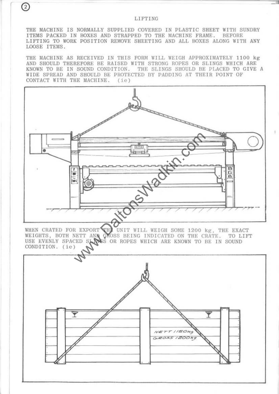
Wadkin BGB 2500 User manual

,
, I
I
I
'I
1
I
• I
•
'J
'.
rOR
SERVICE,
SPARES
A/ID
TOOLING
CONTACT:-
BUIISGRtEII
(COLNn
LTD.,
LODGE
HQUO:,
TIIA"II'DEN,
Nr.
COWl.
LANCASH
I
RE
•
GR!AT
BRITAIN.
TEL.
0282
86~310
TLX.
635032
(BURCOL-G)
8GB
2500&3000
Belt Sander
WHEN
ORDERING
SPARES
OR
REQ~STIHG
SERVICE
PL£ASE
QUOTE
f
ULL
SERIAL
HUMBER
AND
INDICATE
MODEL
TYPE
PL£ASE
INSERT
SERIAL
NUMBER
OF
YOUR
MACHINE
HERE
MODIFICATIONS
ARE
MADE
TO
THESE
BOOKS
f
RO
M
TIME
TO
TIME
AS
IT IS
OUR
CONSTANT
POLICY
TO
IMPROVE
THE
DESIGN
Of
BURSGREEN
MACH
IIIES. I T IS
TKERUORE
UIPOftTANT
THA
T TilE
90011
SUPPLIED
.ITH
TltE
MACH
I
IIE
BE
USED
AS
AN
INST
RUCTION
MANUAL.
,
BOOKNOB654
•
www.DaltonsWadkin.com

I
I
I
I
I
I
I
I
I
,
I
I
I
I
I
I
I
I
I
HEALTH
&
SAFE
TY
SAFETY
OF
WOODWORKING
MACHINES
Woodwork
ing
machines
ca
n
be
dangero
us
if
improperly
use
d.
The
wide
range
of
work
of
wh
ich
they
are
capable
,
requires
adequate
safeguar-
ding
arrange
ments
against
possible
h
azards.
M
any
injuries
t o
machinists
are
caused
by
carelessness
or
failure
to
use
the
guards
provided
or
to
adjust
them
correctly.
WA
DKIN LTD
.•
supp
ly
machinery
des
ig
ne
d
for
maximum
safe
t y
which
they
believe
,
as
a
result
of
thorough
t
est
ing
.
mi
n i mi z
es
the
risks
inevi-
table
in
the
ir
us
e . I t
is
the
user's
responsibi
lity
t o
see
that
the
followi
ng
rules
are
complied
w
ith
to
ensure
safety
at
work:
1.
The
opera
t
ion
of
the
machine
should
conform
to
the
req
uirements
of
the
Woodworki
ng
Machines
Regu
l a-
tio
ns
1974
.
All
guar
ds
s
hould
be u
sed
a
nd
adjusted
correctly
.
2.
Safe
methods
o f
working
o
nl
y
shou
l d
be
adopted
as
given
in
the
Hea
lth
and
Safety
Work
Booklet
No.
4l ,
"Saf
ety
in
the
Use
of
Woodwork
i
ng
Machi
n
es",
(obtainable
from
Her
Ma
j
esty'
s
Stationery
Office)
and
as
advised
by
wadk
i n
Ltd
.
3•
,.
5.
Onl y
personnel
trained
in
the
safe
use
of
a
machine
should
ope
rate
i t .
Befor
e
making
a d
jus
tments
or
clear
i
ng
chips,
etc.,
the
machine
should
be
stopped
an
d
all
movement
s h
ou
ld
have
ceased.
All
too
ls
and
cutters
must
be
securely
fixed
and
the
speed
se
lect
ed
must
be
~ppropriate
for
t he
too
ling
.
SAFETY
IS
OUR
WATCHWORD
BUT
THE
USER
MUST
COMPLY
WITH
THE
ABOVE
RULES
IN
HIS
OWII
INTEREST.
WE
WOULD
BE
PLEASE:D
TO
ADVISE:
011
THE
SAFE
USE
OF
OUR
PRODUCTS
.
000
WAO
",N
.TO'
G"'
H N
~ANE
WO
R K
S'
LEI
CE
STER
L H
OPf'
'NGLANO
T
ELEPHO
NE
o~n
7
6g11'
...
,
..
-
---
,
~-,-
.
"....
.
,,,
..
.....
,,,
..
,,
,
"""
..
,
'
......
"
,'
'''
....
~
....
...
_
,~
"."""
t"
..
,
www.DaltonsWadkin.com

1
t
I
I
I
I
I
I
I
I
I
I
I
I
I
I
I
I
I
Specification
Ellewoe
..
nd,nl
len'th
(
Be
tW
""
'rom
..
)
EHe<u.e .o
nd,n,
wi
dt
h (Bet
""
""
f
..
m
..
)
Mul"'"",
hei,h.
un
d
er
..
nd
ln,
!>tl,
RI", Ind
fall
ubl
e ,,,o,or
So""ln, belt len,.I, (±50mm)
Slndln,
belt
w,d, h
Sandlnl
belt mo
tO
r
Slndl
n,
bell .p.ee
d.
l'
p<
ed
Slndi
",
b
elt
p
ull
ey
d
i.
m
..
""
Th
rOl'
d~
pt
h
(Dou
bl
e ,wan
nO«)
Ou
><
u,,
><
.ion
out
let.
Di>
m
..
or
N
et
..
~ICh'
Sh
l
ppln,
dl",en,lo
n.
8GB
2500
""'mm
'
_m
''''''m
,
)7
S
kW
6'1OO
mm
150mm
}.
I_li<W
1S-30
",/
,«
21S
mm
""
mm
150
mm
61
0k
,
}.
47
""
00''''''
""'mm
'_m
'_m
.)7SkW
"",,"m
"'mm
U-l
kW
15_)Oml'.(
llSmm
""m
m
150
mm
6
lS
k,
].95",'
o
,
www.DaltonsWadkin.com

r
LU
'
TI
NG
THE
MACHINE
IS
NORMALLY
SUPPLIED
COVERED
IN
PLASTI C
SH
EET WI
TH
SUNDR
Y
lTEMS
PACKED
IN
BOXES
AND
STRAPPED
TO
THE MACHINE FRAME. BEFORE
LIFTING
TO
WORK
POSITI
ON
REMO
VE SH
EET
I
NG
AND
ALL
BOXES
ALOKG
WITH
ANY
LOOSE ITEM
S.
TilE
)!ACIIINE
AS
RECEIVED IN
TillS
FOIUl WIl.L WEIGH APPROXIMATELY 11
00
kg
ANI) SIlOULD THEREFORE BE
RAISED
lUTE! STRONG ROPES OR
SLINGS
WIIICH ARE
KN
OWN
TO BE
IN
SOUND
CONDITION.
TilE
SL
f
KGS
SHOULD BE PI..ACED TO
GIVE
A
WID
E SPltEAO
AND
SHOULD
BE
PROTECTED
BV
PADDING
AT
THEIR
POINT Ot'
CONTACT WITH T
HE
MACHINE .
Uc)
o
WHEN
CRATW
FOR EXPORT
TilE
UNIT
WILL
WEIGH SOME
1200
k~.
TilE
EXACT
W
EIGHTS,
30TH
NETT
AND
GIlOSS
BEING
INDICATED
ON
TlU; CHA1'E. TO
LIFT
USI::
EVENLY SPACED
SLINGS
OH
ROPES
\I
'
HIel!
ARE
KNOWN
TO
BE
IN
SOUN
D
CONDI
TI
ON.
(ie)
www.DaltonsWadkin.com

r
11
1.1
LIFTING
NOTES
1)
WHEN
LIFTING
WITH
ROPE
TYPE
SLINGS
PROTECT
AROUND
CaHNERS
OR
SHARP
EDGES
WITH
OLD
SACKING.
2)
WHEN
USING
PO
W
ER
HOISTS
LIFT
SLOWLY
FROM
GROUND
LEVEL
TO
ASCERTAIN
STABILITY
OF
LIFT.
A
LOAD
SHOULD BE
RAISED
IN
TilE
AIR
TO BE
SUSPENEDED
AS
LEVEL
AS
POSS
IBLE. IF
ON
LI F
TING
TilE
LOAD
SHOWS
SIGNS
OF
TILTING
LOWER
OFF
AND
READJUST
SLINGS.
3)
NEVER
llAISE
A LOAD
wr
TH LOOSE
ITEMS
UPON
IT.
1)
WflEN
MOVING
MACHINE
OR CRATE TO
FOUNDATION
POINT
VIA
OVERHEAD
IHOCK OR
HorST,
BEFORE
MOVING
OFF
LOWER
LOAD
nOWN
TO
WITHIN
A
COUPLE OF INCHES
OFF
GROUN
D
LEVEL.
5)
WlmHE
LIFTING
HOOKS EYE BOLTS
OR
SP
ECIAL
GRABS ARE
PROVIDED
r:NSUH~:
SUCH
FITMENTS
ARE
SECURED TO
TilE
LOIID BEPORE
LIFTING
.
IJ
6)
IlEFOIU;
USIN
G
ANY
ROPE ,
BELT
SL
ING
OR
CHAINS ENSURE
IT
IS
IN
SOUNIl
I .
CONDITION
. CUT OR FRAYED
ROPES,
BELTS
OR
CHAINS
WITH
SPRAINED
Oil
SUSPECT
LIN
KS SHOULD NEVER BE
USED.
11
D
o
u
[]
/1
I1
11
11
n
11
7)
1I'1lEN
OPF-LOADING
MACHINE
OR
CRATE , STAND WELL
CLEAR.
S)
KEEP
LOAD
STATIONAR
Y
WHEN
SUSPENDED,
00
NOT ,\LLOI\'
LOAD
TO SWING.
9)
U~
:I'OIlE
LI
FTING
CHECK MACHINE
OR
CRATE FOR
ANY
SPF:CIAL
LIFTING
I N
ST
ltuCTIONS
.
10)
Jr.
A CHATE I S
DA
M
AGED
TO THE
POINT
WHERE
IT
I S I
NSECURE,
UNPACK
AND
LIFT
MACHINE
ON
LY.
www.DaltonsWadkin.com

ln
st
a
llation.-
Remove
prote
e
tive
ant
i-ru
st
coa
ting
fr
om
brigh
t
parts
by
applying
a
cloth
soa
k
ed
in
paraffi
n o r
other
so
l
vent
.
Wiring:_
The
motor
and
control
gear
have
been
wired
In
befo
r e
des
pat
ch,
t he r
efore
all
that
is
r e
quired
to
be
done
i s
to
eo
nne
e t
the
main
s
supply
to
the
star
ter
, o r
isolator
where
fitted
.
POINTS
TO
NOTE
WH
EN
C
ONNECT
I
NG
TO
POWER
SUPPLY: -
1
Check
voltage,
phase
and
frequency
.
2 -
It
is
important
tha
t
the
correct
cable
Is
used
to
delive
r t
he
co
r
re
ct
voltage
to
the
starter.
RUNNING
ON
LOW
V
OLTA
GE WILL
DANAG£
MOTOR.
3 •
Check
maln
line
fuses
ar
e
of
eo
rre
e t ca
paeity.
4
Connect
lino
l
ea
ds
to
correct
te
r
mina
ls
(S
EE
WIRING DIAGRAM).
5
Check
all
connect
i
ons
are
so
und.
6 CheCk s
plndle
rota
t
es
in
correct
direetion.
I f
not
re
verse
any
two
of
the
line
le
ad
eonn
e
ct
i o
ns.
FAILURE
TO
START:-
1
Fuse
s ha
ve
blown
or
have
not
been
fitted
.
2 I s
olator
swi
t c h
has
n
ot
been
e l
osed
.
3
Lock
orf
or
stO
p
but
t
on
(when
fit
ted)
has
not
been
releas
e
d.
4
Supply
n
ot
ava
il
ab
le
at
mac
hine.
STOPPAGE
DUR
I
NG
OPERA
TlON
&0
fAILURE
TO
RESTART:-
1
OverloadS
have
tripped
. I f
hand
r e-
se
t.
se
t
by
p
ressing
button.
If
auto
m
atic
t h
ey
will
re-set
after
a
short
pe
r
iod.
2
Fuses
have
blown.
FOUNDATION:
-
Due
to
the
large
area
co
ve
red
by
t he b
ase
it
is
not
r
equired
to
fix
the
machin
e
to
the
floor
and
as
such
f o
undation
fix
t u
re
s
are
not
provided.
However,
fo r
these
eustomers
wh
o
require
a
permanent
foundati
on
the
followi
ng
sugges
ti
o n
Is
ma
de
in
the
form
of
lour
b
ra
ckets.
(eg)
LI
86
".,
I
Drl
//
~
...........
.rN-N
~,.
,
.....
4.a/{
.
"
1/
'--
,.
~
!
-'
2.
L
I
I
I
1
1
www.DaltonsWadkin.com

r
11
"
cl
11
11
I!
11
11
11
,.
C"_
c
~
I'
..a
-
"cl=
' Y _
)'
& <
'0'
. ,
It
.-=-
••
,
,,
,,
:;,
,
0-
0.
,,-
/
N.-.;
,
CWl'A
•
.........-
_
""
v""
~
~ky
$,,
'-
""""'
'''.
•
•
.-
• • r-'
'"
'------
'
.'<;--;--
..
, J
. J
L-
.~
.L
•
CO
-0 •
"
T
,
,..
--L-
/i /"(3)
, I
O
"'~"--
-
---1-..:::;
r·
.
~
'
0
...
)
n-Q,,""-----I--
'O
,
I
,
,
,
, -• ,
'1
"','4'
~
i)
,
,
(
I
I
www.DaltonsWadkin.com

1
~
0
ABRAS
IVE BELTS
For
tr
ansp
ort
a
tio
n r
easo
ns
the
machine
will
be
sup
plied
without
the
be
lt
fitted
and
as
s u
ch
any
belts
ordored
to
be
su
pplied
with
the
machine
will
be
packed
in
separate
boxes
affixed
to
the
trame
.
BELT DIMENSIONS
8G
B
2500
:-
BGB
3000
:-
6900
mm
(22'
I")
x
150
mm
(6
n)
7900
rmI
(25'11")
x
150
mm
(6")
The
above
dimensions,
plus
the
machine
model
type
and
serial
number
must
be
given
when
re-
o
rderin
g
belts.
REM
OV
AL,
REPLACEMENT
AN
D
TRACK
I
NG
OF
SANDING
B~;L'I'S
To
remove
and
repla
ce
abrasive
belts
the
fo
llowin
g
procedure
should
be
ad
opted
.
1 . Remove
belt
guard
cover
A
trom
idler
pulley
cnd
of
machine
and
s w
ing
open
du
st
hood
gu
ard
B
at
d
rive
pulley
cn
d.
2.
Turn
-h
and
lever
C
tn
clockWise
direction
to
Slacken
be
l t
until
it
is
possible
to
lift
belt
from
pulleys
and
over
wooden
fence
on
the
oversanding
table
.
On
machines
with
sanding
discs
fitted
to
dr
i
ve
pulley,
the
bel
t
wtll
require
li
ft
ing
over
disc
back
plate,
tllerefore,
belt
may
require
slac
k
eni
ng
f u
rther
than
machines
which
are
not
fitted
with
this
featu
re.
3.
Before
reUt.ting,
it
is
impo
r
tant
that
the
conditjon
of
the
replacement
beit
is
checked
and
found
to
be
in
good
cond;tion
(l.
e
.)
fr
ee
from
culs,
cracks
or
toars
.
RUNNING WITH
WOR
N
OR
DEFECTIVE
BELTS
CAN
BE DANGEROUS.
4.
To
replace
belt,
reverse
pro
ced
ure
o
utlined
In
point.
(2)
and
re-tension
by
turning
hand
lever
C
In
anti
-
clockwise
dl
rection
(DO
NOT
OVERTENSION,
SEE
POINT
X).
TRACKING
It
may
be
found
that
after
replacement
Or
during
the
running
life
of
a
bel
t
that
the
t.rack
or
running
alignment
requires
ndjustment.
in
order
that
the
belt
runs
equally
over
each
pulley
and
does
not
te
nd
to
'run-
off
'.
TO UNDERTAKE
THIS
OPER
ATION THE FOLLOWING PROCEDURE SIlOULD BE
ADOPTED.
1.
Remove
idler
pulley
guard
cover
and
by
turning
t he
handlever
C
tensio
n b
olt
t o
polnt
where
all
Slackness
i s
removed
but.
belt
Is
not
fully
t.ensioned
as
it
would
be
for
use
under
running
con
d
itio
ns.
2.
Rota
t e
idler
pulley
by
hand
and
whil
S
t.
rotat.lng
slacken
screw
D
and
nut
E.
3.
St
ill
rot
a
t.
i
ng
pulley.
turn
sc
rew
}'
ln
e
ith
e r
direct
i o n
until
belt
ls
ce
ntral
on
width
of
pulley
drivo
face
.
A~
this
pOint
re-lock
sc
rew
D
and
nut
E.
4 .
Replace
all
cov
er
s
and
tension
belt
by
turning
h
an
dle
C
until
t
here
Is
4 6
mm
clearance
betw
ee
n
shoulder
on
sh
alt
and
cas
tin
g
at
point
X.
I
I
I
I
I
I
I
~
,
www.DaltonsWadkin.com

:I
,
, I
I
J.
,
11
"
I,
,
I ,
I:
I
I
I
I
I
I
"
I ,
I.
"
,,
I
"
,
f
c
B
'----
_.
~
-.
c
www.DaltonsWadkin.com

TABLE
RISE & FALL
The
tab
le
rise
and
fall
motion
Is
powered
by
a
.37
kw
(t
h.p.)
motor
via
w
orm
an
d
wormwheel
to
a
rack.
A
cross
-
shaft
A
transmits
the
drive
to
the
idle
r
pulley
end
ra
ck,
whilst
a
link
collar
B
allows
both
pinions
to
be
adjusted
to
take
up
the
drive
against
the
rack
simul
taneous
l~'.
The
worm
drive
unit
is
prepacked
with
he
avy
duty
grease
and
will
require
no
further
attention.
lIowever,
the
teeth
of
both
vertical
racks
shou
ld
be
periodically
cle
aned
and
smeared
with
lubricant
as
should
the
slideways.
RISE &
FAL
L (OPERATION)
To
ope
rate
the
rise
and
fa
ll
press
gree
n
start
butt
o n C
on
main
control
panel,
when
pr
essed
th
e
reo
panel
light
will
Illuminate
indicating
power
available
at
machine
.
Switch
D
cont
r
ols
the
direction
of
movement
and
can
be
turned
to
either
side
of
the
'OFF'
position
towards
the
indicator
arrows
on
the
panel
face.
The
switch
is
spring
loaded
and
will
return
to
the
'O
FF
'
positinn
when
hand
pressure
is
released
thereby
stopping
the
motion.
•
II-tPORTANT
•
2 .
TO
C
HANG
E DIRECTION
OF
TABLE
RISE
&
FALL
MOTION
'
(1e)
FRO
M
TO
LOWER
OR
VISE-VERSA,
THE
S
WIT
CH
WILL PASS
THROUGH
TUE
'OFF'
POSITION
AND
AS
SUCH
WILL
REI1UIRJ<;
THE
START
BUTTON
C DEPRESSING
AGAIN
IN
ORDER
TO
CO
NTIN
UE
IN
THE
OPPOSITE
DIRECTION.
BELT
T\m
SPEED,
}'ORWARO/REVERSE
CONTROL
On a
stan
dard
machine
a
two
speed
directional
control
switch
E
is
titted
to
e
nable
the
belt
to
run
in
either
direction
whilst
two
speeds
( 1
5m/sec
and
30m/sec)
are
available
in
either
direction
as
indicated
on
the
panel.
To
start
the
belt
switch
E
must
be
in
t
he
'OFF'
pOSition
then
by
pressing
start
buttnn
C
supply
will
be
available
at
controls
as
indicated
by
panel
light.
Belt
can
now
be
started
by
turn
in
g
the
swi
t
ch
in
the
direction
of
rotation
desired
as
indi
cated
on
the
panel
(i
e)
CLOC
K""l
SE
ROTATION
""H
EN
US
I
NG
MA
IN
TABLE,
ANTI
-CLOCKW
I SE
WHEN
US
ING
OVERTABLE
. I
Wh
en
i t i s
required
t o
run
at
the
fastest
speed
the
switch
shou
ld
be
h
J:!
ld
in
the
slnw
p
osition
until
speed
has
built
up
bero.s
switchilli;t"
to
top
speed
.
Thi
s
applie
s
when
running
in
either
direction
when
start
ing
trom
standstill.
For
ch
anging
direction
of
rotation
(ie)
fr
om c l
oc
kwise
to
anti
clockwise,
the
switch
should
be
left
at
the
'OFF'
position
unti
l r o
tati
o n
has
ceased
be
fore
Switching
to
o
pposite
dir
ect
i
on
.
When
it
is
required
tn
stop
the
machine
press
stop
button
C
and
return
Switch
E
to
'OFF'
position.
THE
ABOVE
PO
INTS
SHOULD
ALWAYS
BE
OBSERVED
TO
EL
IM
INATE RISK OF
DA
MAG
E
TO
M
OTOR
AND
ABRASIVE
BE
L
TS.
On
sJng
l e
speed
models
the
above
pnints
i n
the
main
apply
especially
when
c
hanging
direction
of
r
ota
ti
o n .
I
1
www.DaltonsWadkin.com

A
www.DaltonsWadkin.com

----
-------
-
--
SANDING TABLE
The
sanding
table
fram
e
is
s
uppo
rted
on
two
sli
de
bar
s A wh
ic
h
in
t
urn
~
r
un
between
nylon
guid
e
rol
lers
mounted
on
sealed
b
ea
ring
s .
Eac
h
s
lid
e
bar
run
s b
etween
fo
ur
rollers,
the
lowe
r
pair
B b
eing
o n
conce
ntri
c
sha
f
ts
wh
i
lst
the
to
p
pa
ir
C
are
mo
unt
ed
on
ecce
ntri
c
sh
a f t s 11
to
fac
ilit
a
te
adjustment
. Th
ese
rollers
h
ave
be
en
s e t
correctly
prior
to
despa
t c h a
nd
s h
ould
no
t r
eq
u
ire
any
furt
h
er
atten
tion
.
To e n
su
re
smooth
runn
i
ng
of
th
e
tab
l e
clean
the
slide
bars
reg
u
larly
~
to
prevent
r
esi
n bu
ild-
up
DO
NOT
OIL
BARS.
Nylon
br
us h
wipers
D
ar
e f
itte
d
at
either
end
of
th
e
slide
frames
,
t h
ese
sho
uld
be
replaced
when
wo
rn
.
TABLE
WOOD
PIEC
ES
The
t
able
woods
are
simply
screwed
to
the
metal
framewo
rk
of
the
ta
b
le
and
a r e
manufact
ur
ed
from
high
q
ua
l
ity
ha
rdWOOd.
Replacement
pieces
can
be
supplied
to
order
or
made
from
any
similar
mater
i
al
with
a
sectio
n
of
20
mm
x
70
mm
x
800
mm
i n
length.
WOO
DEN
TABLE FENCE
A
wooden
table
fence
is
s
upp
lied
to
provide
a
datum
stop
for
the
work
-
piece
. I t
is
designed
to
dro
p
between
t he
table
wood
pieces
and
can
t he r e f
ore
be
pOSitioned
in
any
space
along
the
tabl
e .
However,
for
best
results
and
imp
r
ove
d
ext
r
action
t he
fence
shou
ld
be
posi
t
ione
d
at
the
n
eares
t
poi
n t
to
the
fan
extr
ac
tion
ch
u
te
and
the
workpiece
butted
up
to
it
as
illustrated
a t
point
E .
Rep
~
acemen
t
fence
pieces
can
be
supplie
d
to
orde
r Or
made
from
goo
d
qua
l
ity
hardwood
of
the
sectional
dimensions
shown
:,€
o
11
11
11
11
11
i
I
I
1
I
I
I
1
1
1
www.DaltonsWadkin.com

I
•
j
. . 1
@
www.DaltonsWadkin.com

@
FLOATING
SANDER
PAD
The
floating
pad
is
~ounted
on
sealed
bearings
within
the
hearing
ho
using
A.
Each
bea
rin
g
is
mounted
on
an
eccentric
pin
which
has
been
adjusted
prio
r
to
despatch
to
give
easy
movement,
and
should
require
no
further
attention
less
that
of
ensuring
that
the
floatin~
pad
bar
B
i s k
ept
clea
n
and
lightly
oiled.
Tile
whole
uni
t
is
operated
by
a
long
counter-balanced
hand
le
C
and
th
e
counter-balance
w!)ight
II
is
actjustah18
by
unlocki
ng
SC
rew
E,
t o
Suit
the
operator.
The
contact
pad
F
is
fitted
with
an
anti-friction
material
which
can
be
replaced
by
removing
the
t
wo
re
tainer
s
trip
s G.
k
eplacemen
t
anti-friction
materi
a l
can
be
supplied
to
orde
r ,
The
contact
pad
F
can
be
adju
sted
by
un
locking
sc
r
ew
H
and
sliding
the
mounting
bracket
along
t
he
handle
arm,
HAND
SANDER PAD
A
small
hand
he l d
sanding
pad
is
suppUed
for
work
on
intricate
workpieces.
This
unit
is
al
s o
fi
tted
with
an
anti-friction
surround
which
can
be
r
eplaced
as
outlined
above.
B
G
- '
I
I
:1
~I
'I'
I ,
,
'11
• I
al
.1
:11
:11
:11
'11
www.DaltonsWadkin.com

@
OVER
SANDING
TABLE
The
over
sanding
table
ls
useful
for
a
va
r
iety
of
11ght
sanding
work
such
as
drawers
and
many
othe
r box
fo
rms.
It
Should
be,
however,
remembered
that
the
direction
of
belt
rotation
must
be
changed
by
mean
s
ot
t
he
two
speed
directional
control
switch
previously
mentioned
and
that
all
work
should
be
undertaken
as
near
to
the
dust
hood
as
possible
to
ens
u
re
maximum
extra
c
ti
on
. At
the
exhaust
hood
aperture
i t
will
be
not
iced
tha
t a n
adjus
t
able
wood
baf
f
le
A I s
fItted
which
shou
1d
remain
w
ithln
8
to
12
nun
of
the
be
l t
at
all
times.
IMPORTANT:- B}:LT
ROTAT
I
ONAL
D
IR
ECTI
ON
WHEN
USING
OVER
TABLE
IS
ANTI
CLOCKW
I
SE.
www.DaltonsWadkin.com

DUST EXT
RACTIO;
, ( DUST HOODS, FAN
UNI
T
ET
C . )
G
ood
~
x
t
r
act
i
o
n
i s i
mp
o r
ta
nt a nd as
such
bo
th
mo
dels
of
BGB
ca
n be
of
f e r
ed
to
s u
it
yo
u r r
equ
ir
eme
nt
s
in
th
i s a r
ea
.
I MACHINE FOR CONNECTION TO
EXI
S
TI
NG
FACT
OR
Y DUST SYST
EM
In
th
is
case
the
machine
i s
supplied
without
a
self
co
n t a
in
e d
mo
t o r
iSed
fa
n u
nit,
hut s i
mply
a n
adaptor
a t
the
drive
n
pulley
e
nd
of
150
mm
dill.
. , wh
ich
is
fo
r
co
nn
ecti
ng t o
you
r
existi
n g e x
haust
system
(see
f i g . A)
2 MAC[l I
NE
TO
BE
USE
D
IN
CONNECT
IO
N WI TH
DU
ST COLLEC
TING
UN
IT
Whe
re t he
mach
i
ne
is
to
be
used
wi
th
a
col
l
ec
ti
ng
u ni t
eit
he
r
ex
isti
ng
Or
of
o u r
man
u
factu
r e t h"
mach
i.ne
wi
ll
be
s u
pp
l
ied
wi
t h
the
mo
t o r
ise
d
fill
l un
it
(s""
fig
.
B)
. The
co
l
lec
t
or
u
nit
of
Burs~ree
n
manu f
ac
t u
re
consists
of
a
stee
l
cabinet
and
<.:onnecti
ng p i pDS . Wi t hi n t
he
c a b
in
et
a
canvaS
bay,
is
hun~
vertica
l
ly
to
collect
the
dust
r e Si
due
.
The
sl'stem
wo r
ks
as
fo
l
lows.
when
t
he
machine
is
run
nin
g
the
p r
essu
r e o f
ai
r
moved
th
rough
t
ll
e
pipe
to
the
collector
by
the
fan
i n
fl
at
e s t
he
bag
but
do"s
n
ot
trap
the
a
ir
i n
as
muc h
as
t
he
air
cun
pass
fr
ee
l y
throu~
ll
t he
fi.bro
of
the
<':~lnvas
but
du
st
part
i c l
es
cannot,
this
becoming
trapped
withi.n
the
bag
and
bei
ng
co
l
lected
thel·e
. T
he
bag
r
equires
emptying
wh
en
it
is
approximately
50
-
60
% f
ull
and
shou
l d
n
ot
be
allowed
to
overfill
as
this
will
reduce
the
co
l.
lecto
r s
efficicncy
.
To
)'
pmove
t he
bag
rolo
a
se
the
webbing
strap
at
the
neck
o f
the
main
inl
e t
inside
t he
cabinet
.
3
~M::H
I
NE
TO
BE
USED W
IT
]]
~
I
OTORISED
COLLECTION
UNIT
Where
ordered
t he
mach
i
""
will
be
supp
l
ied
w
it
h
out
the
fan
un
it
bu t
s i
mp
l y a n
adaptor,
as
outlined
in
pa
r t
1.
for
connection
to
a
motorised
u
nit
.
Detailed
operati
ng
and
service
instr
u
ctions
are
supplied
wit.
h t h"
unit
.
Technical
details
worthy
of
not
e
on
t he
above
unit
are
: -
DUST
CON
T
AINlm
CAPAC ITY
----
___
__
_
__
_
_____
___
__
4 c
u.
ft.
.
F I LTER
AREA
---
__
_
__________________
_
__
_
____
_
__
67
sq
.
ft.
pi':HFOm
II
NG
C\PAG
1LI
TY (NORMAL
COND
1T 1
0NS)
6 .
5"'
W. G.
at
300
C
.F.M
NOTE
: -
,n
t\OR~J,\L
SEHV 1
CE
PERI
OD
CLEAN FAN,
PIP
ES OR
DUC
T
~
ETC .
OF
AN
Y
DUST
GU
I
LD
-
UP
WHICH
HAS
A])1IE
R
ED
TO
THESE
Cm
rpONEN
TS.
OB
SE
RV
E .IANUFACTUREHS SEH
VI
CE
& CLE
AN
I
NG
IN
ST
RUCT
IO
NS FOR
CO
LLECTOR
UNITS
S'I"Rlcn.Y
.
i
ll
I1
I1
I1
I1
)
1
1
J
I1
I
I1
11
I
11
11
11
11
[
~
www.DaltonsWadkin.com

~
========
~====~®
~
i
W
,'
I
i
,
I
I
i
i
I
j
j
i
i
'--
\
l \
i
i I
i
~
I
I
I
I
www.DaltonsWadkin.com

ABR
A
SIVE
BELTS
~
DISCS AVAILABLE
Please
not
e
wh
en
or
dering
belts
state
size
of
machine.
Both
belts
and
discs
ar
e
sol
d
in
packs
of
ten
of
each
grade
only,
theref
ore,
prices
given
upon
application
for
quote
will
be
pe
r
pack.
350
MY
(14")
Dr A.
DISCS
Aluminium
Oxide
paper
backed
grit
150
MW.
(6")
WIDE BELTS
(PA
PER
)
Aluminium
Oxide
paper
backed
grit
150
IotM
(6")
WIDE
BELTS
(CLOTH)
Aluminium
o
xide
cloth
backed
grit
. . ,
o
1
I
11
,
'
/0
'/0
o
I
I
I!
,
'/0
2/0
o
,
I
I!
2
80
60
50
"
36
150
100
80
60
50
"
36
150
lOO
80
60
50
"
36
RO
L
LS
OF
1
50
M~l
(6")
WIDE
ABRASIVE
50
lot
(165')
LONG
Availabl
e
in
Aluminium
grits
150
down
to
36
.
bobbins
and
wher
e
the
FOR
PNEUMATIC
SANDING
o
xido
paper
backed
only,
are
available
in
The a
bove
is
intended
for
use
with
snnd
in
g
fa
cility
Is
available
for
making
onos
own
bellS.
BOBBINS
Three
sizes
of
bObbin
are
availab
l e
63
mm
dia
.
(2
5/8").75
ITJTl
(3")
dla.
100
ITJTl
(4")
dia.
Pl
ease
state
s
17
;6
required
when
orderi
n
g.
Each
grit
is
sold
in
packs
ot
te
n.
Aluminium
oxide
cloth
sleeves
grit
o
,
I
80
60
50
11
11
11
11
11
11
1:
11
11
11
11
11
11
11
11
11
11
11
11
11
11
www.DaltonsWadkin.com

--
~
®
~
I
I
I
I
~
I
.
~
,
~
~
EXTRA
ITEMS
~
~
I
,
I
I
.
~
~
www.DaltonsWadkin.com

EX
T
RA
ITEMS
DISC
a
CANTING
TABLE
The
d16c
attachment
complete
wit)!
ca
nting
table
is
suitable
for
square
bevel
and
external
ra
dii
work.
The
angle
of
the
cant
ls
easily
set
as
de
S
ired
and
can
be
locked
rigidly
1n
place
by
nut
A.
The
angle
of
the
cant
can
be
set
450
down
and
100
up
from
horiZQntal
and
is
limited
at
each
of
these
points
by
the
slot
in
the
pivot
bracket
B.
The
disc
I s
350
mm
in
dia.{14")
and
IS
secured
to
the
driven
pulley
by
means
of
an
adap
tor,
which
fits
directly
t o t he
pulley
via
the
existing
mounting
bolts,
and
by
a
central
c
up
head
bolt
C. The
drive
between
the
belt
pulley
and
disc
Is
assured
by
the
fitment
of
a
peg
and
slo
t
c
ut
into
tbe
outer
surface
of
the
belt
pulley
(see
inset).
Wh
ere
the
above
unit
is
supplied
at
a
later
date
t
han
the
machine
(ie)
not
a fa
ctor
y
fitted
extra,
the
following
procedure
should
be
adopted
for
installation.
The
unit
supplied
will
comprise
ot
the
Disc
table
(OOB
83)'0'
Disc
table
quadrant
(OOB
82)'B'
Disc
quadrant
guide
(BGB
98)'E'
plus
the
required
studs
and
screws
and
lock
nut;
al
ong
with
the
disc
and
adapt
or
mentioned
above.
1 Remove
pulley
mounting
bolts
F
and
reCit
with
adaptor
(BGB 4
)'G'
.
2
O!!or
disc
H
to
pulley
and
mark
pOSition
of
drive
peg
cutou
t
(see
inset)
6
Im1
wide
slot
0").
3
Secure
disc
H
to
pull
ey
with
12
mm
bolt
C.
4
,
6
7
8
All
holes
for
mounting
the
cnnting
table
are
drilled
o n
the
end
-
frame
(see
i
llustrat
i
on).
Screw
quadrant
guide
'E'
to
endtrame
with
the
three
1.15
x
20
countersunk
alIen
screws
provided
I.
Lock
W12
x
60
stud
J
1nto
hole
provided.
Place
disc
table
and
quadrant
'0'
and
'B'
onto
guide
and
over
stud
and
secure
with
M12
locknut
A
and
spring
washer
provided.
Check
that
the
correct
angles
to
wh
i
ch
the
table
can
be
canted
are
obtainable
.
11
11
11
1
1
1
1
1
1
I
I
1
]
]
www.DaltonsWadkin.com
This manual suits for next models
1