WAGO 879-3000 4PU User manual

Operating Instructions
Version: 082022V1.6
© 2022 distributed by WAGO –All rights reserved.
WAGO Energy Meters (MID)
with Push-in CAGE CLAMP® and Lever
879-3020 4PS
879-3000 4PU
879-3040 2PU CT

Table of Contents
1 Safety information ................................................................................................................................ 3
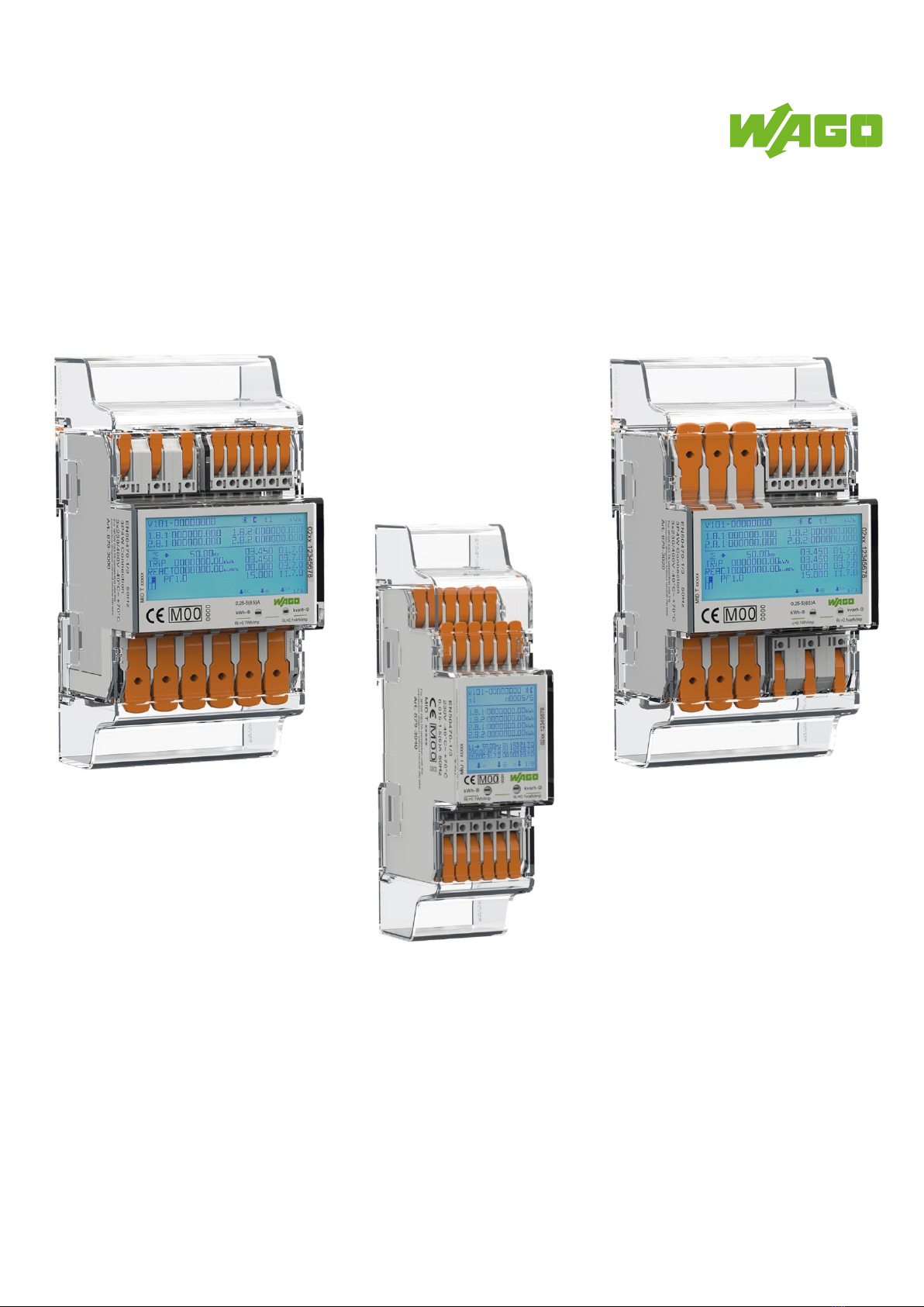
2 Introduction .......................................................................................................................................... 5
3 Certificates ............................................................................................................................................ 6
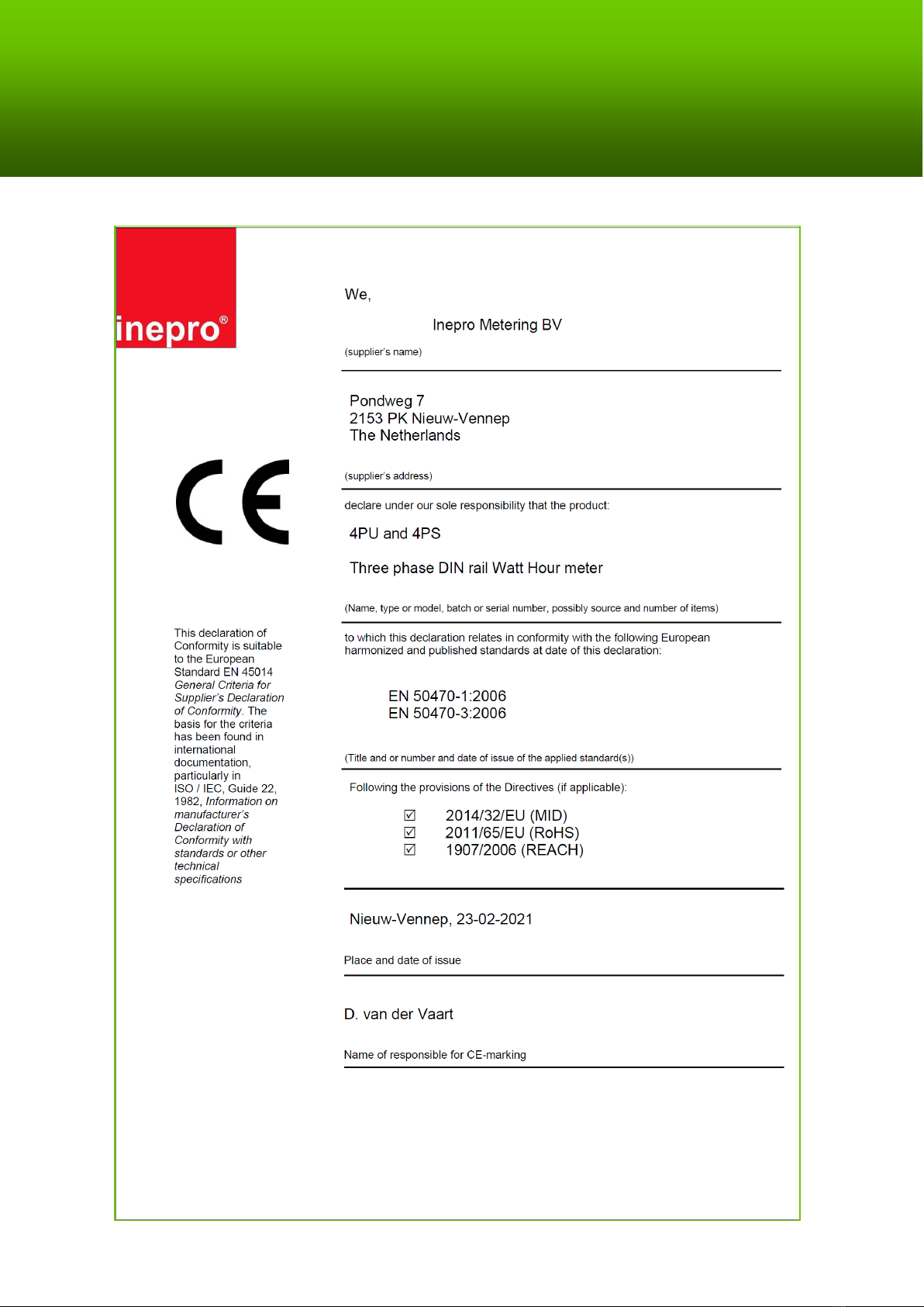
3.1 MID Declaration of Conformity: 4PU and 4PS .................................................................................................6
3.2 CE Declaration of Conformity: 4PU und 4PS ...................................................................................................7
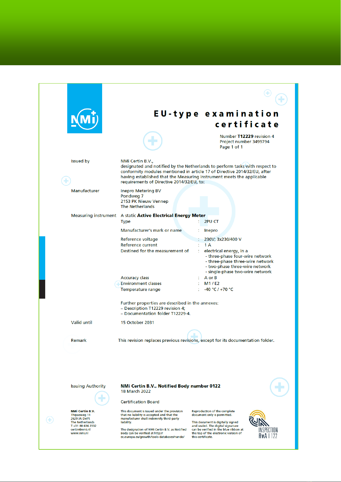
3.3 MID Declaration of Conformity: 2PU CT .........................................................................................................8
3.4 CE-Declaration of Conformity: 2PU CT ...........................................................................................................9
4 Specifikations................................................................................................................................................10
4.1 Performance Criteria ...................................................................................................................................10
4.2 Measurement Deviations.............................................................................................................................11
4.3 Software Version Checksum ........................................................................................................................11
4.4 Bluetooth® Specifications ...........................................................................................................................11
4.5 M-Bus Communication Specifications ...........................................................................................................11
4.6 Modbus®/RS485 Communication Specifications ...........................................................................................11
4.7 Enclosure Dimensions .................................................................................................................................12
4.8 Connection Technology...............................................................................................................................12
4.9 Connection Diagram ...................................................................................................................................13
4.9.1 Connection Diagram 879-3000 (4PU) ........................................................................................................13
4.9.2 Connection Diagram 879-3020 (4PS) ........................................................................................................14
4.9.3 Connection Diagram 879-3040 (2PU CT) ...................................................................................................15
5 Installation.......................................................................................................................................... 16
6 Operation ............................................................................................................................................ 17
6.1 Display Part 1 (MID-relevant) ......................................................................................................................17
6.2 Display Part 2 (MID-relevant)......................................................................................................................17
6.3 Display Part 3 (non-MID-relevant) ...............................................................................................................17
6.4 Process Diagram 4PU/4PS & 2PU CT............................................................................................................18
6.5 Settings .....................................................................................................................................................19
6.6 Bluetooth®................................................................................................................................................19
6.7 Settings via Buttons....................................................................................................................................20
6.7.1 Password ................................................................................................................................................20
6.7.2 Tariff ......................................................................................................................................................20
6.7.3 S0 Pulse Output.......................................................................................................................................21
6.7.4 Pulse Type Setting ...................................................................................................................................21
6.7.5 S0 Pulse Length.......................................................................................................................................21
6.7.6 Modbus® ID ...........................................................................................................................................22
6.7.7 Modbus®-Baudrate .................................................................................................................................22
6.7.8 Modbus® Parity ......................................................................................................................................22
6.7.9 M-Bus-ID ................................................................................................................................................22
6.7.10 M-Bus Baud Rate ...................................................................................................................................23
6.7.11 Backlight ...............................................................................................................................................23
6.7.12 Power-down Counter .............................................................................................................................23
6.7.13 Trip Counter ..........................................................................................................................................23
6.7.14 OBIS Codes ...........................................................................................................................................24
6.8 OBIS-Codes - Tables...................................................................................................................................24
6.9 Set Transformer Ratio (2PU CT only) ...........................................................................................................26
7 Troubleshooting .................................................................................................................................. 28
7.1 Error / Diagnostic Indication........................................................................................................................28
7.2 Technical Support.......................................................................................................................................28
Appendix 1 –Multi-Tariff Function ........................................................................................................ 29
A1.1 Switching Tariffs between T1 and T2 .........................................................................................................29
A1.2 Switching Tariffs to T3 and T4 ..................................................................................................................29
Appendix 2 –M-Bus ............................................................................................................................... 30
A2.1 Communication via the M-Bus Interface.....................................................................................................30
A2.2 M-Bus Register Map..................................................................................................................................31
A2.3 M-Bus Write Register ................................................................................................................................32
Appendix 3 –Modbus®.......................................................................................................................... 33
A3.1 Communication via the Modbus® Interface ...............................................................................................33
A3.2 Modbus® Register Map ............................................................................................................................34
A3.3 Modbus® Write Register...........................................................................................................................38

WAGO Operating Instructions 4PU/4PS/2PU CT 3
1 Safety information
Information on your own safety
This manual does not contain all of the safety measures for operating this meter, as particular operating
conditions, local codes or ordinances may require additional measures. However, it contains information
that must be observed for your personal safety and to avoid damage to property. This information
highlighted by a warning triangle with an exclamation mark or a lightning bolt, depending on the degree of
actual or potential hazard:
Warning
This means that failure to heed the notice could result in death, serious injury or significant
property damage.
Caution
This means there is a risk of electric shock and failure to heed the notice will result in death,
serious injury or significant property damage.
Qualified Personnel
The installation and operation of the device described in this manual must only be carried out by qualified
personnel. Only qualified electricians according to EN 50110-1/-2 and IEC 60364 are qualified personnel in
the sense of this manual.
Intended Use
This device may only be used for the applications specified in the catalog and in the user manual and only
in connection with devices and components recommended and approved by WAGO. The device is an open
system. Install the device in lockable enclosures, cabinets or electrical operation rooms only. Access must
be limited to authorized, qualified staff having the appropriate key or tool.
Proper Handling
Requirements for the trouble-free, safe operation of the product are proper transport, storage, installation
and connection as well as careful operation and maintenance. During operation, certain parts of the meter
can carry dangerous voltages.
•During assembly, startup, operation, maintenance and troubleshooting, adhere to the specific accident
prevention provisions applicable to your machine/system, such as DGUV Regulation 3 “Electrical
installations and equipment".
•To minimize any hazardous situations resulting in personal injury or to avoid failures in your system,
the data and power supply lines shall be installed according to standards, with careful attention given
to ensuring the correct terminal assignment.
•Always adhere to the EMC directives applicable to your application.
•The meter is intended for installation in an “M1” mechanical environment, with minor shocks and
vibrations and an “E2” electromagnetic environment, according to Directive 2014/32/EC. The meter is
intended for indoor use. The meter must be installed in a suitable IP-rated enclosure, in accordance
with local regulations. The devices have been developed for use in an environment that meets the
criterion of the IP20 protection type. There is protection against figure injury and protection against
the ingress of solid foreign objects greater than or equal to 12.5 mm, but no protection against water.
Unless otherwise specified, operation of the devices in wet and dusty environments is prohibited.

4 WAGO Operating Instructions 4PU/4PS/2PU CT
•Ensure that the conductors used are suitable for the maximum current of this meter and the prevailing
environmental conditions.
•Make sure all leads are properly connected before applying power to the meter.
•Make sure that protection against accidental contact is in place after installing the energy meter. If this
cannot be guaranteed on site for operational reasons and bare conductors can be seen, attachment of
the terminal cover is required.
•For each individual application, the devices are supplied from the factory with a dedicated hardware
and software configuration. These modules contain no parts that can be serviced or repaired by the
user.
The following actions will result in the exclusion of liability on the part of WAGO GmbH & Co. KG:
• Repairs
• Changes to the hardware or software that are not described in the operating instructions
• Improper use of the component.
Further details are given in the contractual agreements.
Please send your suggestions for modifications to modified or new hardware or software
configurations directly to WAGO GmbH & Co. KG.
•Never break any seals (if provided on this meter) to open the front cover as this will affect the
functionality or accuracy of the meter and will void any warranty.
•Do not drop the meter or subject it to physical shock as it contains high-precision components. The
components could break and negatively affect the measurement.
•Only use conductor cross-sections approved for the terminal blocks with appropriately stripped ends.
Exclusion of Liability
We have reviewed the contents of this manual and have made every effort to ensure that the descriptions
are as accurate as possible. Nevertheless, deviations from the description cannot be completely ruled out,
so that no liability can be accepted for any errors or omissions in the information. The information in this
manual is reviewed regularly and any necessary corrections incorporated into subsequent editions. Should
you have any suggestions, please do not hesitate to contact us.

WAGO Operating Instructions 4PU/4PS/2PU CT 5
2 Introduction
Although we produce the energy meters according to international standards and our quality control is
very strict, it is still possible that this meter has a defect or failure, for which we apologize. Under normal
conditions, your product should provide you with years of trouble-free service. If there is a problem with
the energy meter, you should contact your dealer immediately. The enclosures of the energy meters are
sealed and must not be opened. Opening the enclosure or damaging the seal will void the warranty.

6 WAGO Operating Instructions 4PU/4PS/2PU CT
3 Certificates
3.1 MID Declaration of Conformity: 4PU and 4PS

WAGO Operating Instructions 4PU/4PS/2PU CT 7
3.2 CE Declaration of Conformity: 4PU und 4PS

8 WAGO Operating Instructions 4PU/4PS/2PU CT
3.3 MID Declaration of Conformity: 2PU CT

WAGO Operating Instructions 4PU/4PS/2PU CT 9
3.4 CE-Declaration of Conformity: 2PU CT

10 WAGO Operating Instructions 4PU/4PS/2PU CT
4 Specifikations
Material Polycarbonate (PC 940A)
Nominal voltage (Un) AC 230 / 400 V (3~)
Operating voltage 3 x 230 / 400 V ±20 %
Insulation capacity:
-AC voltage resistance 4 kV für 1 Minute
-Pulse volate resistance 6 kV …1,2μS waveform
Base current (Ib)
Maximum nominal current (Imax)
Operating current range 0,4%Ib … Imax
Overcurrent resistance 30 Imax für 0,01s
Operating frequency 45 … 60Hz
Internal consumption ≤2 W/Phase - ≤10 VA/Phase (active - reactive)
Pulse output red LED on the front 10.000 imp/kWh
S0 pulse output rate (imp/kWh) 10.000 (2PU CT)/2.000/1.000 (4PU und 4PS)/100/10/1/0,1/0,01
(default = bold)
Pulse width Selectable 2 … 99 ms (depending on pulse output rate)
Memory The data is stored for up to 10 years, even without a power
supply.
4.1 Performance Criteria
Humidity during operation ≤ 75 %
Humidity during storage ≤ 95 %
International storage EN50470-1/3
Accuracy class B (=1 % accuracy)
Protection against
Dust and water IP51 (front side); IP20 (connection)
Protection class II
Ambient temperature (operation) -40 … +70°C
4PU und 4PS
2PU CT
5 A
1 A
65 A
5 A
Item/
Product
Conductor cross-section/
Conductor cross-section
Rated current/
Rated current
Ambient temperature/
Ambient temperature
40 °C
55 °C
70 °C
879-3000
879-3020
25 mm²
(fine-stranded conductor)
65 A
x
45 A
x
16 mm²
(fine-stranded conductor with insulated ferrule)
65 A
x
55 A
x
35 A
x
16 mm²
(fine-stranded conductor)
65 A
x
50 A
x
35 A
x
10 mm²
(fine-stranded conductor with insulated ferrule)
55 A
x
45 A
x
30 A
x
10 mm²
(feindrähtige Leiter/fine-stranded conductor)
55 A
x
40 A
x
30 A
x
6 mm²
(fine-stranded conductor with insulated ferrule)
41 A
x
39 A
x
27 A
x
6 mm²
(fine-stranded conductor)
41 A
x
37 A
x
25 A
x
4 mm²
(fine-stranded conductor with insulated ferrule)
32 A
x
27 A
x
17 A
x
4 mm²
(fine-stranded conductor)
30 A
x
25 A
x
15 A
x

WAGO Operating Instructions 4PU/4PS/2PU CT 11
4.2 Measurement Deviations
0,05 Ib
Cosϕ= 1
±1,5%
0,1 Ib
Cosϕ= 0,5L
±1,5%
Cosϕ= 0,8C
±1,5%
0,1 Ib…Imax
Cosϕ= 1
±1,0%
0,2 Ib…Imax
Cosϕ= 0,5L
±1,0%
Cosϕ= 0,8C
±1,0%
4.3 Software Version Checksum
The checksum is used to control the meter's software. You can use the checksum to check whether the software is
fully functional or whether it contains errors.
For 4PU/4PS:
For 2PU CT:
Software Version
Checksum
Software Version
Checksum
V1.18
27325923
V1.02
59629173
V1.21
27327238
V1.03
59607739
V1.26
59269903
V1.04
59811839
V1.28
59268366
V1.34
59268366
If you have found a discrepancy in the checksum, contact technical support immediately at tel. +49 (0) 571/887 -
4.4 Bluetooth
®
Specifications
Protocol BLE 4.2
Frequency range Bluetooth® 4.0: 2402 …2480 MHz (40 CH)
4.5 M-Bus Communication Specifications
Bus type 2-wire (M-Bus)
Baud rate 300, 600, 1200, 2400 (standard), 4800 and 9600
Parity Even (even; unchangeable, fixed by default))
Range ≤1000m
Downlink signal Master to slave. Voltage Modulation
Uplink signal Slave to master. Current Modulation
Cable (recommended) JYSTY (nx2x0.8)
Protocol EN13757-3
Unit loads/standard load 1
Max. number of bus subscribers 64 per bus*
4.6 Modbus®/RS485 Communication Specifications
Bus type RS-485
Protocol Modbus RTU with 16-bit CRC
Baud rate 1200, 2400, 4800, 9600 (standard), 19200, 38400, 57600 and
115200
Parity Even/none (standard)/odd
Address range 1-247 adjustable
Maximum bus load 60 meters per bus*
Range ≤1000 m
•Note that the maximum number of meters depends on the converter, the baud rate (the higher the
baud rate, the smaller the number of meters that can be used) and the circumstances under which the
meters are installed.

12 WAGO Operating Instructions 4PU/4PS/2PU CT
4.7 Enclosure Dimensions
4PU / 4PS 2PU CT
4.8 Connection Technology
Clamp technology Push-in CAGE CLAMP®
Actuation type Lever
WAGO 2616 Series
Solid conductors 0.75 …16 mm² / 18 …4 AWG
Fine-stranded conductors 0.75 …25 mm² / 18 …4 AWG
Fine-stranded conductors with ferrule and plastic collar 0.75 …16 mm²
WAGO 2604 Series
Solid conductors 0.2 …4 mm² / 24 … 12 AWG
Fine-stranded conductors 0.2 … 4 mm² / 24 … 12 AWG
Fine-stranded conductors with ferrule and plastic collar 0.25 …2.5 mm²
Push-in technology can be used for solid conductors, fine-stranded conductors and fine-stranded conductors with
ferrules. In the case of fine-stranded conductors, the levers must be opened for connection.
Circuit diagram: Solid conductors
Circuit diagram: Fine-stranded conductors
with ferrule
4PU / 4PS
2PU CT
Height without cover
92 mm
97 mm
Height with cover
140 mm
140 mm
Width
72 mm
36 mm
Depth
63 mm
63 mm
Weight
0.34 kg (net)
0.2 kg (net)

WAGO Operating Instructions 4PU/4PS/2PU CT 13
4.9 Connection Diagram
4.9.1 Connection Diagram 879-3000 (4PU)
4PU –3P4W
IN L1: Input Phase L1 –OUT L1: Output Phase L1
IN L2: Input Phase L2 –OUT L2: Output Phase L2
IN L3: Input Phase L3 –OUT L3: Output Phase L3
N: Neutral conductor
4: S0 output 1 (+)
5: Ground for S0 (-)
6: S0 output 2 (+)
7: Modbus®(A)
8: Ground for Modbus®(B) / M-Bus (-)
9: M-Bus (+)
10, 11: Tariff (230 VAC)
4PU –3P3W Open Delta (Aron; for IT networks only!)
Please put a bridge between N and U2 - IN!
IN L1: Input Phase L1 –OUT L1: Output Phase L1
IN L2: Input Phase L2 –OUT L2: Output Phase L2
IN L3: Input Phase L3 –OUT L3: Output Phase L3
N: External bridge on terminal point IN L2
4: S0 output 1 (+)
5: Ground for S0 (-)
6: S0 output 2 (+)
7: Modbus®(A)
8: Ground for Modbus (B) / M-Bus (-)
9: M-Bus (+)
10, 11: Tariff (230 VAC)
4PU –3P3W Delta
IN L1: Input Phase L1 –OUT L1: Output Phase L1
IN L2: Input Phase L2 –OUT L2: Output Phase L2
IN L3: Input Phase L3 –OUT L3: Output Phase L3
N: Not used
4: S0 output 1 (+)
5: Ground for S0 (-)
6: S0 output 2 (+)
7: Modbus®(A)
8: Ground for Modbus®(B) / M-Bus (-)
9: M-Bus (+)
10, 11: Tariff (230 VAC)
4PU –1P2W 1-phasig
IN L1: Input Phase L1 –OUT L1: Output Phase L1
IN L2: not used –OUT L2: not used
IN L3: not used –OUT L3: not used
N: Neutral conductor
4: S0 output 1 (+)
5: Ground for S0 (-)
6: S0 output 2 (+)
7: Modbus®(A)
8: Ground for Modbus®(B) / M-Bus (-)
9: M-Bus (+)
10, 11: Tariff (230 VAC)

14 WAGO Operating Instructions 4PU/4PS/2PU CT
4.9.2 Connection Diagram 879-3020 (4PS)
4PS –3P4W
IN L1: Input Phase L1 –OUT L1: Output Phase L1
IN L2: Input Phase L2 –OUT L2: Output Phase L2
IN L3: Input Phase L3 –OUT L3: Output Phase L3
N: Neutral conductor
4: S0 output 1 (+)
5: Ground for S0 (-)
6: S0 output 2 (+)
7: Modbus®(A)
8: Ground for Modbus®(B) / M-Bus (-)
9: M-Bus (+)
10, 11: Tariff (230 VAC)
4PS –3P3W Open Delta (Aron; for IT networks only!)
Please put a bridge between N and U2 - IN!
IN L1: Input Phase L1 –OUT L1: Output Phase L1
IN L2: Input Phase L2 –OUT L2: Output Phase L2
IN L3: Input Phase L3 –OUT L3: Output Phase L3
N: External bridge on terminal point IN L2
4: S0 output 1 (+)
5: Ground for S0 (-)
6: S0 output 2 (+)
7: Modbus®(A)
8: Ground for Modbus®(B)/M-Bus (-)
9: M-Bus (+)
10, 11: Tariff (230 VAC)
4PS –3P3W Delta
IN L1: Input Phase L1 –OUT L1: Output Phase L1
IN L2: Input Phase L2 –OUT L2: Output Phase L2
IN L3: Input Phase L3 –OUT L3: Output Phase L3
N: Not used
4: S0 output 1 (+)
5: Ground for S0 (-)
6: S0 output 2 (+)
7: Modbus®(A)
8: Ground for Modbus®(B)/M-Bus (-)
9: M-Bus (+)
10, 11: Tariff (230 VAC)
4PS –1P2W 1-phasig
IN L1: Input Phase L1 –OUT L1: Output Phase L1
IN L2: not used –OUT L2: not used
IN L3: not used –OUT L3: not used
N: Neutral conductor
4: S0 output 1 (+)
5: Ground for S0 (-)
6: S0 output 2 (+)
7: Modbus®(A)
8: Ground for Modbus®(B) / M-Bus (-)
9: M-Bus (+)
10, 11: Tariff (230 VAC)

WAGO Operating Instructions 4PU/4PS/2PU CT 15
4.9.3 Connection Diagram 879-3040 (2PU CT)
2PU CT –3P4W
IN CT1: Input CT1 –OUT CT1: Output CT1
IN CT2: Input CT2 –OUT CT2: Output CT2
IN CT3: Input CT3 –OUT CT3: Output CT3
U1 ; U2 ; U3: Voltage L1 ; L2 ; L3
N: Neutral conductor
4: S0 output 1 (+)
5: Ground for S0 (-)
6: S0 output 2 (+)
7: Modbus®(A)
8: Ground for Modbus®(B) / M-Bus (-)
9: M-Bus (+)
10, 11: Tariff (230 VAC)
2PU CT –3P3W Open Delta (Aron; for IT networks only!)
Please put a bridge between N and U2 - IN!
IN CT1: Input CT1 - OUT CT1: Output CT1
IN CT2: not used - OUT CT2: not used
IN CT3: Input CT3 - OUT CT3: Output CT3
U1 ; U2 ; U3: Voltage L1 ; L2 ; L3
N: External bridge on terminal block IN U2
4: S0 output 1 (+)
5: Ground for S0 (-)
6: S0 output 2 (+)
7: Modbus®(A)
8: Ground for Modbus®(B) / M-Bus (-)
9: M-Bus (+)
10, 11: Tariff (230 VAC)
2PU CT –3P3W Delta
IN CT1: Input CT1 –OUT CT1: Output CT1
IN CT2: Input CT2 –OUT CT2: Output CT2
IN CT3: Input CT3 –OUT CT3: Output CT3
U1 ; U2 ; U3: Voltage L1 ; L2 ; L3
N: Not used
4: S0 output 1 (+)
5: Ground for S0 (-)
6: S0 output 2 (+)
7: Modbus®(A)
8: Ground for Modbus®(B) / M-Bus (-)
9: M-Bus (+)
10, 11: Tariff (230 VAC)
2PU CT –1P2W 1-phasig
IN CT1: Input CT1 –OUT CT1: Output CT1
IN CT2: not used –OUT CT2: not used
IN CT3: not used –OUT CT3: not used
U1 ; U2 ; U3: Voltage L1 ; L2 ; L3
N: Neutral conductor
4: S0 output 1 (+)
5: Ground for S0 (-)
6: S0 output 2 (+)
7: Modbus®(A)
8: Ground for Modbus®(B) / M-Bus (-)
9: M-Bus (+)
10, 11: Tariff (230 VAC)

16 WAGO Operating Instructions 4PU/4PS/2PU CT
5 Installation
•Switch off all supply sources of the energy meter and the devices connected to it and secure them against being
switched on again before working on the system.
•Check the voltage with a meter to ensure the system is de-energized.
•Installation must only be carried out by qualified personnel who are familiar with the applicable rules and
regulations.
•Use insulated tools to install the device.
•A fuse, thermal isolator or single pole circuit breaker should be placed on the supply line and not on the neutral
line.
•The connection cable connecting the equipment to the external circuit should be rated for the maximum current of
the fuse or other overcurrent protection device used in the circuit in accordance with local regulations.
•An external fuse or circuit breaker should be installed on the supply lines to isolate the meter and power supply
devices. It is recommended to place this fuse or circuit breaker near the meter as it is more convenient for the
operator. Both the fuse and circuit breaker must meet the specifications of the building's electrical design and all
local codes.
•An external fuse or thermal shutdown used as an overcurrent protection device for the meter must be installed on
the supply-side wiring. It is recommended to place this protection also near the meter to facilitate the work of the
operator. The circuit breaker must conform to the specifications of the building's electrical design and all local
codes.
•To prevent tampering, an enclosure may be protected with a lock or similar device. Furthermore, the cover caps of
the terminal points can be sealed using seals.
•The meter must be installed on a fireproof wall.
•The meter must be installed in a well-ventilated and dry place.
•The meter must be installed in a protective box if the meter is exposed to dust or other contaminants.
•The meter has been developed for mounting on DIN rails in accordance with EN 60715.
•If the meter is installed in an area with frequent overvoltages, e.g., due to thunderstorms, welding machines,
inverters, etc., the meter must be protected by a surge protection device.
•The device should be sealed immediately after installation to prevent tampering.

WAGO Operating Instructions 4PU/4PS/2PU CT 17
6 Operation
6.1 Display Part 1 (MID-relevant)
Part 1 of the display shows the MID-relevant values such as software version number, meter serial number, CRC code,
current tariff and unit of the MID-relevant measurement units (kWh). The meter serial number and CRC code are
displayed alternately every 10 seconds. If Bluetooth®communication is enabled, the Bluetooth®icon is displayed. If
Modbus®or M-Bus communication is enabled, square brackets are displayed.
6.2 Display Part 2 (MID-relevant)
Part 2 of the display shows the MID-relevant measured values.
The OBIS codes are used to identify the corresponding measured values:
Forward direction:
1.8.1: Positive Active Energy in Tariff 1
1.8.2: Positive Active Energy in Tariff 2
1.8.3: Positive Active Energy in Tariff 3
1.8.4: Positive Active Energy in Tariff 4
Reverse direction:
2.8.1: Negative Active Energy in Tariff 1
2.8.2: Negative Active Energy in Tariff 2
2.8.3: Negative Active Energy in Tariff 3
2.8.4: Negative Active Energy in Tariff 4
The tariff values are displayed alternately so that T1 and T2 are displayed together, T3 and T4 together.
The meter has a 6+3-digit kWh display. When it reaches 999999.999, this value goes back to 000000.000.
6.3 Display Part 3 (non-MID-relevant)
Part 3 of the display shows the non-MID-relevant data such as current direction, day counter, reactive energy, power
factor, current quadrant, frequency, active power, apparent power, reactive power, voltage and current.
The display pages can be changed using the capacitive touch keys on the front of the measuring device. (Total - L1 -
L2 - L3). Furthermore, the OBIS codes and units change as soon as the meter detects a different current flow direction
or when the meter changes to a different quadrant. A list of all OBIS codes can be found on page 24.
4PU und 4PS
2PU CT
4PU und 4PS
4PU and 4PS
2PU CT
2PU CT

18 WAGO Operating Instructions 4PU/4PS/2PU CT
6.4 Process Diagram 4PU/4PS & 2PU CT

WAGO Operating Instructions 4PU/4PS/2PU CT 19
6.5 Settings
4PU and 4PS
2PU CT
There are three buttons on the front of the
meters, marked with a green line. To enter
settings mode, press and hold the center button
for > 3 seconds.
The following is displayed:
6.6 Bluetooth®
4PU and 4PS
2PU CT
If the arrows >> point to the Bluetooth®icon,
press the middle button:
The Bluetooth®interface of the meter is now
enabled and ready for communication with the
WAGO Energy Meter Configurator app. To
connect to the meter, scan the QR code with
the app or browse the Bluetooth®environment
by selecting the appropriate menu item in the
app.
If a Bluetooth®connection is established, the
Bluetooth®icon is shown on the display:
(Description of the WAGO app in Appendix 4 –
Bluetooth®)

20 WAGO Operating Instructions 4PU/4PS/2PU CT
6.7 Settings via Buttons
4PU and 4PS
2PU CT
Settings can also be made using the capacitive
touch buttons on the front of the meter. Use the
left and right buttons to cycle through the
options. Press the middle button to confirm the
settings. Select the menu icon (3 horizontal
lines) to enter the settings menu:
To access the settings menu, enter the 4-digit
password (default 0000). Confirm each digit (0-
9) by pressing the middle button:
After entering the correct password, the
settings menu appears:
6.7.1 Password
4PU and 4PS
2PU CT
The settings via the buttons are protected by a
password. This password is also relevant for the
settings via Bluetooth®. The password is 0000by
default. The password can only be changed
using the buttons.
6.7.2 Tariff
4PU and 4PS
2PU CT
When delivered, Tariff 1 is selected. The tariff to
be used is selected via the WAGO Energy
Configurator app or the settings menu. Tariff 2
can also be selected by applying a voltage (230
VAC) between terminal points 10 and 11. The
energy values of all tariffs are shown in the
middle area of the display. Tariffs 1 and 2 and
Tariffs 3 and 4 are shown here in alternation.
This manual suits for next models
2
Table of contents
Other WAGO Measuring Instrument manuals