Walchem ehe series User manual

EHE Series
Electronic Metering Pump
Instruction Manual
W A L C H E M
IWAKI America Inc.
EHE Series Metering Pumps
Five Boynton Road Hopping Brook Park Holliston, MA 01746 USA
TEL: 508-429-1110 FAX: 508-429-7433 WEB: www.walchem.com

Notice
© 2017 WALCHEM, Iwaki America Inc. (hereinafter “Walchem”)
Five Boynton Road, Holliston, MA 01746 USA
tel (508) 429-1110
All Rights Reserved
Printed in USA
Proprietary Material
The information and descriptions contained herein are the property of WALCHEM. Such
information and descriptions may not be copied or reproduced by any means, or disseminated or
distributed without the express prior written permission of WALCHEM.
This document is for information purposes only and is subject to change without notice.
Statement of Limited Warranty
WALCHEM warrants equipment of its manufacture and bearing its identification to be free from
defects in workmanship and material for a period of two years from date of delivery from the factory
or authorized distributor under normal use and service and otherwise when such equipment is used
in accordance with instructions furnished by WALCHEM and for the purposes disclosed in writing
at the time purchased, if any.
WALCHEM’s liability under this warranty shall be limited to replacement or repair, F.O.B.
Holliston, MA U.S.A. of any defective equipment or part which, having been returned to
WALCHEM, transportation charges prepaid, has been inspected and determined by WALCHEM to
be defective.
THIS WARRANTY IS IN LIEU OF ANY OTHER WARRANTY, EITHER EXPRESS OR IMPLIED, AS
TO DESCRIPTION, QUALITY, MERCHANTABILITY, FITNESS FOR ANY PARTICULAR
PURPOSE OR USE, OR ANY OTHER MATTER.
P/N E00022.U
March 2017

TABLE OF CONTENTS
Thank you for choosing a Walchem E Series metering pump. This instruction manual deals with the correct
installation, operation, programming maintenance, andtroubleshooting proceduresfor the EHE Series metering
pumps. Please read through it carefully to ensure the optimum performance, safety and service of your pump.
1.0 INTRODUCTION ............................................................................................................. 1
1.1 Safety and Caution Notes ............................................................................................ 1
1.2 Principle of Operation................................................................................................... 1
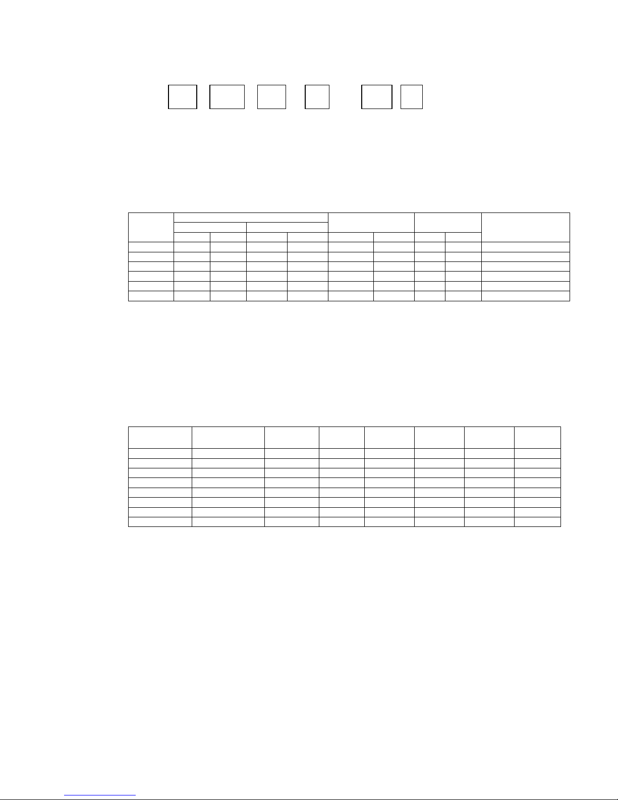
1.3 Specifications............................................................................................................... 2
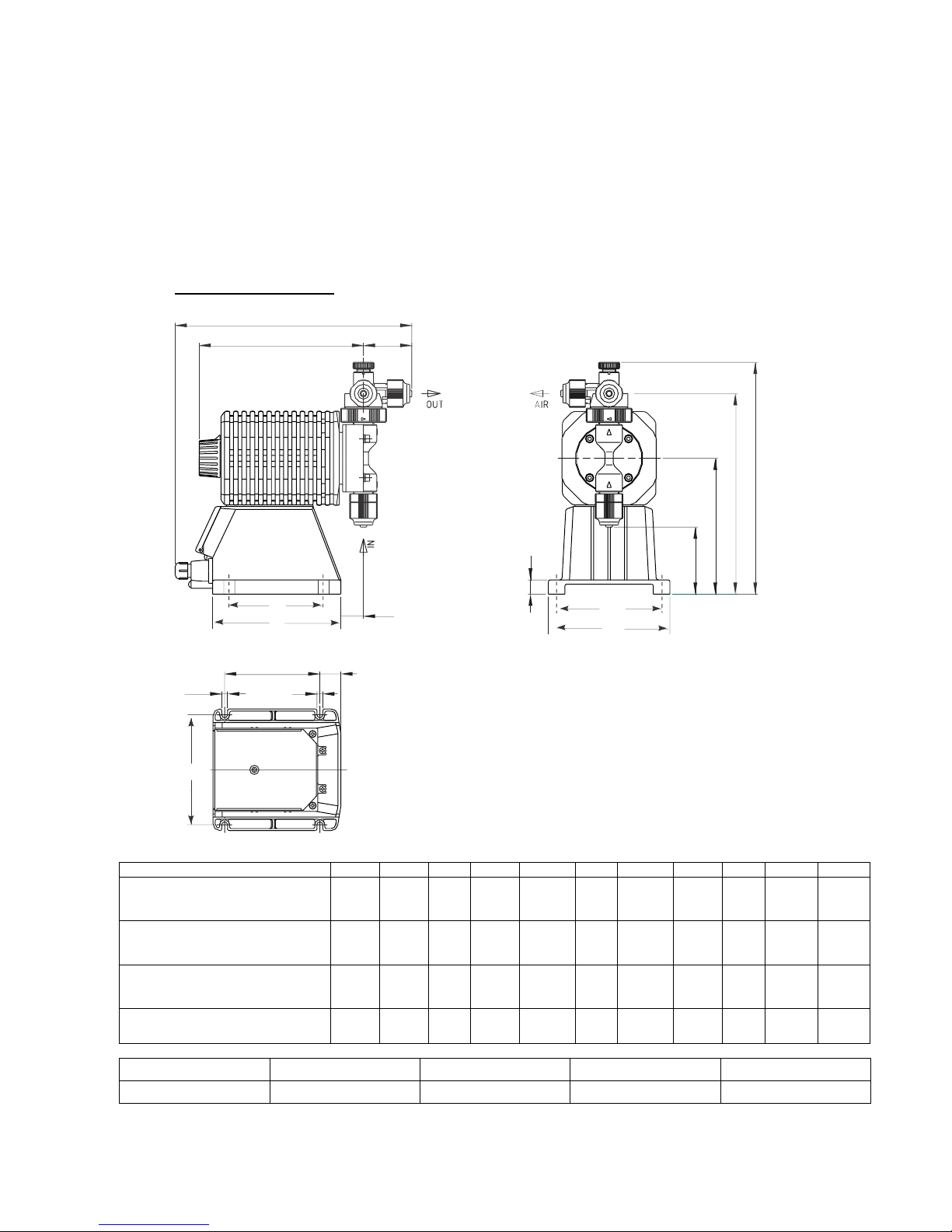
1.4 Dimensions.................................................................................................................. 3
2.0 INSTALLATION............................................................................................................... 5
2.1 Unpacking.................................................................................................................... 5
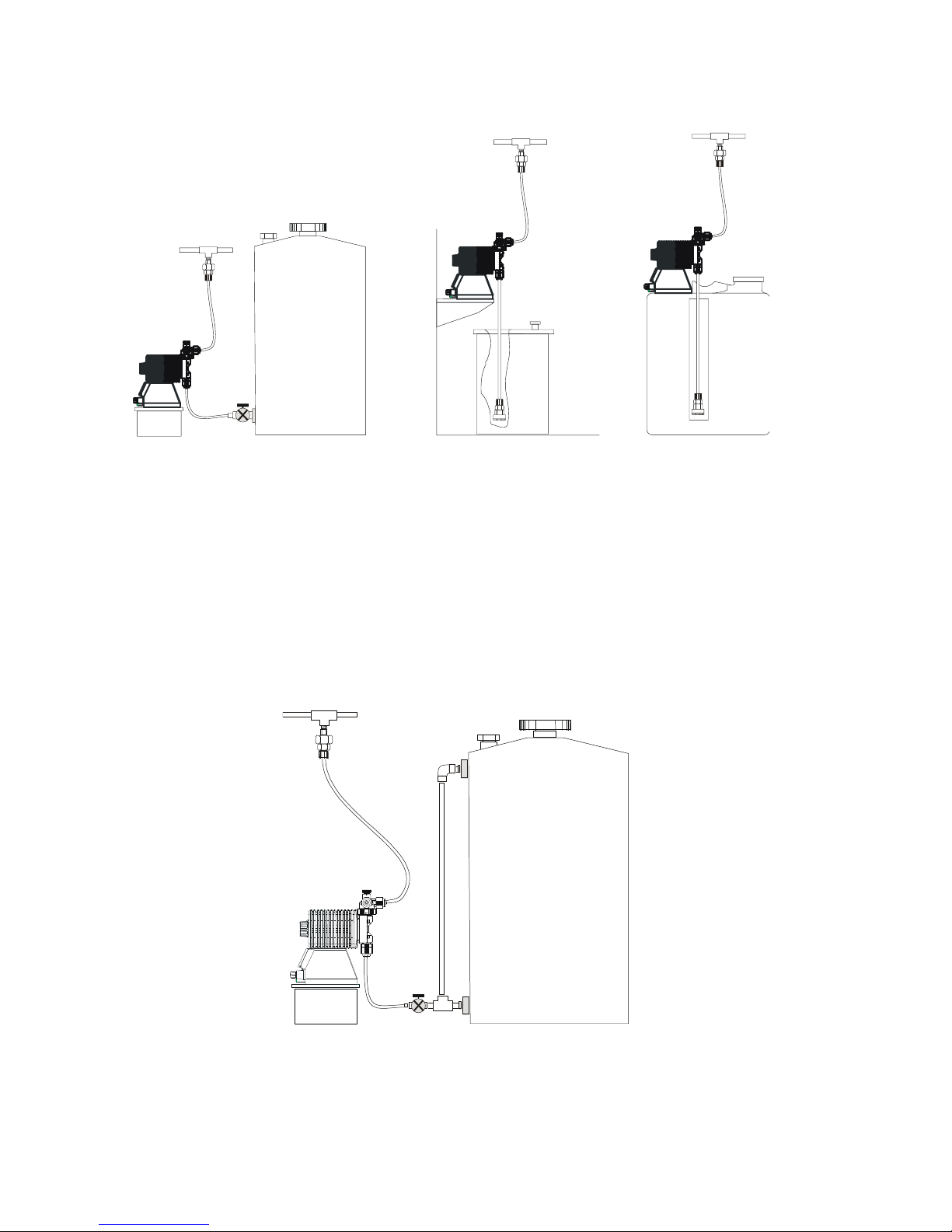
2.2 Location....................................................................................................................... 5
2.3 Supply Tubing.............................................................................................................. 7
2.4 Discharge Tubing......................................................................................................... 8
2.5 Installing Injection Check Valve.................................................................................... 8
2.6 Interlocking Pump ........................................................................................................ 9
2.7 Electrical ...................................................................................................................... 9
3.0OPERATION ................................................................................................................. 10
3.1 Priming....................................................................................................................... 10
3.2 Adjustment................................................................................................................. 10
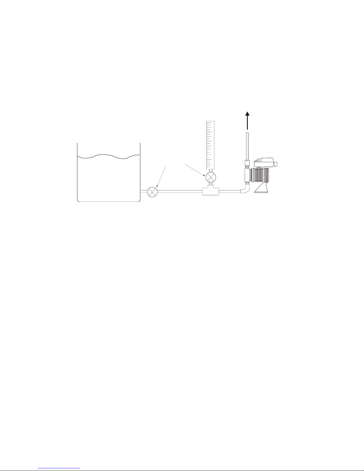
3.3 Calibration.................................................................................................................. 10
3.4 Control Unit Operation and Programming .................................................................. 10
3.5 Input Wiring and Connections .................................................................................... 21
3.6 AC Power Interruption................................................................................................ 22
4.0 MAINTENANCE ............................................................................................................ 23
4.1 Diaphragm Replacement............................................................................................ 23
4.2 Valve Replacement.................................................................................................... 23
4.3 Tubing........................................................................................................................ 23
5.0 EXPLODED VIEW AND PARTS GUIDE ....................................................................... 24
5.1 How to order parts for your metering pump................................................................ 24
5.2 Accessories (Not shown)............................................................................................ 24
5.3 EHE31, 36, 46 Liquid End Exploded View.................................................................. 25
5.4 EHE 56 Liquid End Exploded View............................................................................. 27
5.5 EHE 36-HV Liquid End Parts List............................................................................... 29
5.6 Drive Control Components......................................................................................... 30
5.7 Assembly Part Numbers............................................................................................. 30
5.8 Spare Parts Kit........................................................................................................... 31
6.0 TROUBLESHOOTING................................................................................................... 32
7.0 SERVICE POLICY......................................................................................................... 32

1
1.0 INTRODUCTION
1.1 Safety and Caution Notes
Always wear protective clothing, eye protection and gloves before working on or near a metering pump.
Follow all recommendations of the supplier of the solution being pumped. Refer to the MSDS from the
solution supplier for additional precautions.
Walchem E Series metering pumps should NOT be installed where ambient temperatures exceed
122°F (50°C) or fall below 32°F (0°C). Pumps should always be shielded from direct exposure to the
elements. Black UV resistant tubing should be used if the tubing is exposed to strong UV radiation
(sunlight/lamps).
WARNING Risk of electrical shock! This pump is supplied with a grounding conductor and
grounding-type attachment plug. To reduce the risk of electrical shock, be certain that it is connected
only to a properly grounded, grounding type receptacle with ratings conforming to the data on the
pump data plate. Prior to performing any maintenance on a pump, disconnect the pump from the
electrical power source.
Plumbing Precautions
All tubing must be securely attached to the fittings prior to starting the pump (see Section 2.3). Only
use Walchem tubing with your pump. Tubing should be shielded to prevent possible injury in case of
rupture or damage. UV resistant tubing should be used if the tubing is exposed to UV light. Always
adhere to local plumbing codes and requirements. Be sure that the installation does not constitute a
cross connection. Walchem is not responsible for improper installations. Prior to performing any
maintenance on a pump, depressurize the discharge tubing.
If you are pumping downhill or into little or no system pressure, a back pressure/anti-siphon device
must be installed to prevent over-pumping. Contact your Walchem distributor for additional
information.
Solution Compatibility
CAUTION! This pump has been tested by Underwriters Laboratories Inc. using water only. The
suitability of this pump for use with liquids other than water is the responsibility of the user. For
liquids other than water, select the best-suited liquid end material combination using a chemical
compatibility chart or guidance from the solution supplier.
1.2 Principle of Operation
The E Series electronic metering pump consists of a pump unit, a drive unit, and a control unit. The
drive unit is an electromagnetic solenoid. When the solenoid coil is energized by the control unit, the
armature shaft moves forward due to the magnetic force of the solenoid. The shaft is attached to a
PTFE faced diaphragm, which is part of the pump unit. The diaphragm is forced into the pump head
cavity decreasing volume and increasing pressure which forces liquid in the pump head out through
the discharge check valves. When the solenoid coil is de-energized, a spring returns the armature to
its starting position. This action pulls the diaphragm out of the head cavity increasing volume and
decreasing pressure. Atmospheric pressure then pushes liquid from the supply tank through the
suction check valves to refill the pump head.

2
1.3 Specifications
EH E36 E 1 - PC V
1 2 3 4 5 6
1 Pump Series
EHE Electronic metering pump with external Analog and pulse control or manual speed
control (adjustable to 360 strokes per minute). Manually adjustable stroke length.
(Turndown ratio 1800:1)
2 Capacity/Pressure Rating
Size
Output Capacity
Output per stroke
(mL)
Maximum
Pressure
Conn. Size (in)
Tubing O.D.
(GPH)
(mL/min)
min
max
min
max
min
max
(PSI)
(MPa)
E31
0.0031
5.5
0.189
340
0.189
0.94
150
1.0
½
E36
0.0047
8.5
0.289
520
0.289
1.44
105
0.7
½
E46
0.0067
12.0
0.417
750
0.417
2.08
60
0.4
½
E56
0.0111
20.0
0.694
1250
0.694
3.47
30
0.2
½
E36-HV
0.0033
4.0
0.210
252
0.210
1.05
73
0.5
½ OD x ½ ID (Suc)
E46-HV
0.0067
8.0
0.421
505
0.421
2.10
60
0.4
½ OD x ½ ID (Suc)
3 Control Module
E For use on all EHE models, features analog and external pulse control with pulse
divide and multiply capability.
4 Voltage
1115VAC, 50/60 Hz
2 230VAC, 50/60 Hz
5 Liquid End
Liquid End
Code
Pump Head &
Fittings
Diaphragm*
Valve
Balls
Valve Seat
Valve
Seals
Gasket
Tubing
HV
PVC
PTFE
SS/HC
PCTFE
FKM
PTFE
N/A
VC
PVC
PTFE
CE
FKM
FKM
PTFE
PE
VE
PVC
PTFE
CE
EPDM
EPDM
PTFE
PE
VF
PVC
PTFE
PTFE
EPDM
EPDM
PTFE
PE
PC
GFRPP
PTFE
CE
FKM
FKM
PTFE
PE
PE
GFRPP
PTFE
CE
EPDM
EPDM
PTFE
PE
FC
PVDF
PTFE
CE
PCTFE
PTFE
PTFE
PE
VM
M-PVC
PTFE
CE
FKM
PTFE
PTFE
PE
E56 Model only * Bonded to EPDM
Materials of Construction
CE Alumina ceramic PCTFE Polychlorotrifluoroethylene
EPDM Ethylene propylene diene monomer PE Polyethylene
FKM Fluoroelastomer PTFE Polytetrafluoroethylene
GFRPP Glass fiber reinforced polypropylene PVC Polyvinylchloride (translucent)
M-PVC Machined polyvinylchloride PVDF Polyvinylidenefluoride
HC Hastelloy C276 (spring in HV)
6 Special Head Options
Blank = 1/2” O.D. tube connection and standard accessories. (HV is 1/2” O.D. discharge x 1/2” I.D. suction)
V= Standard 1/2” tube connections with back pressure/anti-syphon valveadded. (Not available on FC models)
T= 3/4” NPT (male) pipe thread connection. (1/2” MNPT on HV pumps). No MAVV.
P= 3/4” NPT (male) connection (1/2” MNPT on HV pumps) with back pressure/anti-syphon valve. No MAVV.
Note: NPT piping connection material of construction will be the same as the liquid end. All pumps include a
manual air vent valve with the exception of FC/HV liquid ends and options P and T.
All pumps include one foot valve, one injection valve, 20 feet of polyethylene tubing and one ceramic weight
with the exception of HV models (tubing only) and options P and T.

3
Adjustment Range
Stroke length adjustment range 20% to 100% Stroke Length
Frequency adjustment range 1 to 360 strokes per minute (1 to 240 strokes per minutes for –HV)
Operating Conditions
Ambient temperature 32 to 122°F (0 to 50°C)
Relative humidity 30 to 90% non-condensing
Liquid temperature 32 to 104°F (0 to 40°C) for PVC based Liquid Ends
32 to 140°F (0 to 60°C) for PP or PVDF based Liquid Ends
1.4 Dimensions
PVC & GFRPP Models
Model
A
B
C
D
E
F
G
H
J
L
W
EHE
31
36
E1
E2
-VC
-PC
-VE
-PE
-VF
6.06
1.05
7.76
6.42
2.28
0.67
9.49
10.95
3.15
11.18
5.75
EHE
46
E1
E2
-VC
-PC
-VE
-PE
-VF
6.06
1.14
7.83
6.42
2.28
0.67
9.86
11.34
2.80
11.25
5.75
EHE
56
E1
E2
-VC
-PC
-VE
-PE
-VF
6.06
1.42
8.13
6.42
2.28
0.67
10.10
11.57
2.38
11.55
5.75
EHE
56
E1
E2
-VM
6.06
1.42
8.13
6.42
2.28
0.67
10.10
11.57
2.38
11.55
5.75
Mounting Dimensions
R
S
T
X
EHE all variations
5.20
4.50
1.00
0.28
L
CE
AB
H
G
D
J
W
F
R
XS T
X
SR
C
L

4
FC and HV Models
Model
A
B
C
D
E
F
H
J
L
W
EHE
31
36
E1
E2
-FC
6.06
1.05
7.76
6.42
0.65
0.67
9.69
3.15
9.53
5.75
EHE
46
E1
E2
-FC
6.06
1.14
7.83
6.42
0.75
0.67
10.00
2.80
9.72
5.75
EHE
56
E1
E2
-FC
6.06
1.42
8.13
6.42
0.85
0.67
10.45
2.38
10.12
5.75
EHE
36/46
E1
E2
-HV
6.06
1.05
7.80
6.42
0.70
0.67
9.69
2.95
9.60
5.75
Mounting Dimensions
R
S
T
X
EHE all variations
5.20
4.50
1.00
0.28
All dimensions in inches
OUT
LCE
AB
IN J
D
H
W
F
T
S
R
XX
C
L
SR

5
2.0 INSTALLATION
2.1 Unpacking
Open the shipping carton and inspect contents for damage. If any items are missing or damaged
contact your local distributor to arrange for replacement.
CAUTION
Pumps are pre-primed with water at the factory. If the application is not compatible with water, drain
and dry before use. Be sure to remove caps from fittings before attaching tubing.
Head bolts may have loosened during storage or shipment. Be sure to check and tighten to 19 lb-in of
torque, as necessary.
The electronics within the pump can be damaged by excessive surges in voltage. Do not install the
pump near high-power electrical equipment that generates high surge voltages. Avoid branch circuits
that also supply power to heavy or other equipment that could generate electrical interference. If
necessary, install a surge suppression device (such as a varistor with a resistance greater than 2000A)
or a noise-reducing transformer at the pump’s power connection.
WARNING: Risk of electrical shock! This pump is supplied with a grounding conductor and
grounding-type attachment plug. To reduce the risk of electrical shock, be certain that it is connected
only to a properly grounded, grounding type receptacle.
2.2 Location
Choose a location for the pump that is clean, dry, vibration –free, close to an electrical outlet, and
allows convenient access to stroke length control, frequency control, and tubing connections. Avoid
areas where ambient temperature exceeds 122°F (50°C) or falls below 32°F (0°C). Pumps should
always be shielded from direct exposure to the elements. Black UV resistant tubing should be used if
the tubing is exposed to strong UV radiation (sunlight/lamps).
This pump is cord connected and not intended for permanent mounting to a building structure.
However, temporary mounting to stabilize the pump during operation may be necessary as long as
tools are not required for the installation or removal of the pump.
Flooded suction (mounting the pump below the level of liquid in the supply tank) is strongly
recommended, especially when pumping liquids that readily generate gas bubbles. Sodium
hypochlorite and hydrogen peroxide are common examples of such liquids. (See Figure 1.)

6
Figure 1 Figure 2 Figure 3
Flooded Suction Shelf Mount Tank Mount
Suction Lift Suction Lift
If flooded suction mounting is not possible, a shelf adjacent to (but not directly above) the supply
tank often works well (see Figure 2). The supply tank or cover can also be used if it has provisions
for mounting a pump (see Figure 3). In any case, the total suction lift should not exceed 5 ft (1.5m).
For extremely gaseous liquids such as Sodium Hypochlorite or Hydrogen Peroxide, pulling from an
external manifold will significantly reduce gas bubbles to the suction side of the pump. This
installation will typically solve most priming issues associated with these gaseous liquids. See Figure
4 for reference.
Figure 4
Flooded Suction for Gaseous Liquids
Sodium
Hypochlorite
Storage Tank

7
The EH-HV Series pumps require a flooded suction or pre-primed condition before operation. Flooded
suction (mounting the pump below the level of liquid in the supply tank) is recommended for proper
operation of high viscosity pumps. (See Figure 1) These pumps are not designed to be self-priming.
The pump is supplied with ½” tube or ½” NPT male suction and discharge connections depending on model.
Mount the pump close to the supply tank and arrange the suction piping to be as short and straight as possible.
Avoid piping installations where air may become trapped in the suction piping.
Figure 5
2.3 Supply Tubing
The supply tubing run should be as short as possible. For flooded suction mounting, install a shut-off
valve with an appropriate tubing connector at the tank outlet. Cut a length of tubing from the coil
supplied and install between the shut-off valve and the pump inlet fitting. For suction lift
applications, install a foot valve on one end of suction tubing and cut the tubing to a length such that
the foot valve hangs vertically about 1 in (25mm) above the bottom of the tank. Avoid any loops in
the tubing run that could form a vapor trap. Running the tubing through a length of rigid pipe will
help to keep tubing straight (see Figure 3). Total vertical suction lift should be no more than 5ft.
(1.5m).
Attach tubing as shown in Figure 5. First slide the coupling nut, small end first, onto the tubing.
Then slide on the clamp ring so that the rounded edges face the end of the tubing. Next push the
tubing onto the tubing adapter fitting. (Tips: Place tubing adapter fitting on a flat surface such as a
table top and press tubing down on top of it all the way to the lip of the tubing adapter fitting. If the
tubing is stiff from cold, dip the tubing end in hot tap water for a few minutes so it will slide on and
flare out more easily. Slide clamp ring down until it tightens over the adapter fitting. Then slide
coupling nut down as far as it will go. Insert this arrangement into the suction valve housing. With
one hand holding tubing and applying slight downward pressure, tighten the coupling nut until secure.
SUPPLY
TANK
TO POINT
OF
APPLICATION
VALVE
Calibration
Column

8
WARNING: All fittings and coupling nuts should be tightened by hand. If necessary, small pliers
may be used to make it snug. DO NOT use excessive force or large wrenches.
Figure 6 Tubing Connections
2.4 Discharge Tubing
Cut a length of tubing long enough to go from the pump to the application (injection) point.
Additional tubing can be ordered from your distributor. Avoid sharp bends or kinks in the tubing and
protect the tubing from sharp edges that could chafe or cut it. If applicable, install the injection valve
in 1/2” NPT thread at the injection point and connect the discharge tubing to the injection valve.
Attach the tubing as described above in Section 2.3, Figure 5.
Note: Most pump models have an air vent valve with two connections on the discharge side of the
pump head. The connection marked 'OUT' is the discharge connection plumbed to the injection point.
The connection marked 'AIR' is the vent connection and tubing should be routed from this point back
to the chemical solution (supply) tank or drum. Refer to Section 1.4 drawing.
2.5 Installing Injection Check Valve
A fitting or tee with 1/2” NPTF threads and sufficient depth should be used to install the injection
valve assembly. If required, trim off an amount of the extension tip until it fits your fitting or tee (see
Figure 7). Attach the supplied tubing to the compression end: cut the tubing square, slide on the
coupling nut, push the tubing to the bottom of the cone (use warm water to soften tubing as
necessary), and hand tighten coupling nut.
The position of the injection check valve can be at any orientation as long as the spring is retained in
the valve. DO NOT REMOVE THE SPRING. Be sure to check/replace the spring as needed.
CAUTION: Some chemicals may have reactions as they are injected into the main flow (ie. sulfuric
acid may react with water causing excess heat). If that chemical is heavier than water, mount the
injection valve as close as possible to vertical, injecting into the bottom of the pipe. This will keep
the injection nozzle facing up and keep the heavier chemistry from draining into the pipe causing
adverse reactions within the injection valve and pipe.
In addition to preventing backflow from pressurized lines, the injection valve will provide a limited
amount of backpressure when pumping into open atmosphere type applications. However, the
backpressure by the injection check valve is very low and can vary. Metering pump output is rated at
TUBING
ADAPTER
CLAMP
RING
COUPLING
NUT
Rounded edge
against tubing

9
maximum backpressure and, depending upon the application, may be higher if the back-pressure is
lower than rated. Additionally, the valve does NOT act as an anti-siphon valve. If siphoning is a
possibility, or if pumping downhill into open atmosphere (open tank), a separate backpressure/anti-
siphon valve must be installed.
NOTE: Siphoning can also occur at the tip of the injection valve because of the high flow rate in the
main pipe flowing past the small injection nozzle (venturi effect). In this case, an anti-siphon device
must be installed to avoid over feeding or siphoning of chemistry into the line. Cutting the injector
tip at an angle or to a different length will sometimes alleviate this problem.
Figure 7
Injection Check Valve Installation
2.6 Interlocking Pump
CAUTION! Control of pump operation is critical. Operation and chemical addition during no flow
situations can create hazardous situations from elevated chemical concentrations and chemical gasses
trapped in the line.
Ensure that during no flow conditions such as when the well pump, main line or recirculation pump is
off, and for pools/spas, in times of backwash,that the metering pump is not allowed to operate. If
using a controller (pH/ORP/pool) for automated control and flow indication is tied into it, pump
operation can be interlocked to the controller.
Interlocking the pump operation can also be done directly using a flow switch located in the water,
main or pool/spa recirculation lines. The flow switch can be tied directly into the pumps to stop
operation during no flow conditions.
2.7 Electrical
WARNING Risk of electrical shock! This pump is supplied with a grounding conductor and
grounding-type attachment plug. To reduce the risk of electrical shock, be certain that it is connected
only to a properly grounded, grounding type receptacle.
CAUTION! The electronics within the pump can be damaged by excessive surges in voltage. Do not
install the pump near high-power electrical equipment that generate high surge voltages. Avoid
branch circuits that also supply power to heavy or other equipment that could generate electrical
interference. If necessary, install a surge suppression device (such as a varistor with a resistance
greater than 2000A) or a noise reducing transformer at the pump’s power connection.
Trim back as needed
to fit tee or fitting
Injection Check Valve
Coupling Nut

10
3.0 OPERATION
3.1 Priming
Install the pump as described in Section 2.0. With the pump plugged in but not pumping, set stroke
length at 100% and frequency at 360 (use the or buttons as necessary to adjust the frequency).
If the pump is equipped with a manual air vent valve, open the knob ½-1 turn; otherwise disconnect
the discharge tubing from the injection valve. Push the START/STOPbutton to start the pump. As
soon as liquid enters the discharge tubing at the pump head, push the START/STOPbutton again to
stop the pump. Close the air vent valve and/or reconnect the discharge tubing to the injection valve.
If the pump does not self-prime, remove the check valve housing on the discharge and suction sides
to make sure the valve cartridges and gaskets are in correct positions (see Section 4.2). Remove and
shake cartridges to make sure ball is loose inside. Wetting cartridges before re-installing will help in
priming.
3.2 Adjustment
The pump will operate best with the stroke length at 100%. If less than full output is required, set the
frequency to the desired percentage of maximum.
Example: Model EHE31E1-VC has maximum output of 5.5 GPH at 360spm and 100%SL.
Desired output is 4.0 GPH.
4.0 ÷ 5.5 = 0.73 or 73%. 73% of 360spm is 263spm.
Press the or buttons as necessary to set the frequency to 263spm.
If very low outputs are required, it will be
necessary to also reduce the stroke length.
(Minimum recommended stroke length is 20%.)
3.3 Calibration
If the application requires the pump to be
calibrated, prime and adjust the pump per
directions above. Then connect a calibration
column to the suction side of the pump and re-
prime the pump to eliminate any air.
Turn the pump on for one minute and read the
amount of liquid pumped from the column.
Adjust the frequency up or down as necessary
and check the output again. When the desired
output is reached, disconnect the calibration
column and reconnect the suction tubing. (See
Figure 8.)
Figure 8
Pump Calibration

11
3.4 Control Unit Operation and Programming
The EHE Series metering pumps can be operated in either manual or external modes. The external
mode can be controlled from a digital or analog external signal. An external stop function is available
for remotely suspending operation of the pump and functions independent of the control mode.
Display/Keypad Overview
UP key. Increases
numeric values. Is
used with EXT key to
select external modes.
DOWN key. Decreases
numeric values. Is used
with EXT key to select
external settings.
WAIT indicator. Visible
when pump is in standby
mode.
Alpha/numeric display. Indicates
stroke frequency, external mode or
external settings.
Start/Stop key.
Manually starts or stops
the pump. This key is
used in setting external
modes and values.
EXT indicator. Visible
when pump is operating
via external input
operation.
EXT key. Push to set
pump for external input
operation. This key is
also used to select
which external mode
and settings.
STOP indicator. Visible
when the pump is stopped
via external signal. The
pump stops pumping.
OVER indicator. Visible when the
input signal exceeds the pump’s
360spm capability or when an input
is received during an external
“STOP”.
SET indicator. Visible
when pump external mode
and/or setting are being
selected.
ON light. Indicates AC
power to the pump and
goes on and off with
each stroke.
12 3
Power
Ground
Digital Input
Stop Input
Analog Input
Sensor Power
DC 12V
10mA MAX.
White
Neutral
Black
HOT
Green
45 6 7 8
_
_
+
+
Power Cord
External Signal Cable
Strain Relief
Nut
Strain Relief
Grommet
Power
Terminal Block
Control Module
Cover
Stroke Length
Knob
External Input
Terminal Block
Control Module
Terminal Block Cover

12
EH-E Program Overview
Notes:
1. Upon power up, display will show software version for approximately 1 second and then move to
whichever mode it was powered down in (WAIT Mode if powered up for the first time).
2. To operate the pump in Manual Operation, press the STOP/START key from the WAIT Mode. Press
the STOP/START key to stop the pump.
3. To operate the pump in EXT Operation, press the EXT key from the WAIT Mode. START/STOP will
stop EXT operation and return to the WAIT Mode.
4. To change input operation between Digital or Analog, press the EXT and keys simultaneously.
Toggle between DIG or ANA with the or keys and select the desired control method by pressing
with the STOP/START key. This will also exit this menu.
5. Input Pulse Memory can be turned on/off in the DIG mode. While selecting DIG in step 4, pressing
the EXT key will move to this selection. On/Off is toggled with the or keys and the EXT key will
switch between multiply and divide. Press the STOP/START key to return to the WAIT Mode.
6. To set the input operation values, press the EXT and keys simultaneously from the WAIT Mode.
The values are changed with the or keys. The EXT key is used to toggle between MULT or DIV
if set in DIG mode and will scroll through the (4) setpoints in ANA mode.

13
Manual Operation
(1) Power ON
When power is applied to the pump, the green indicator above
ON lights up, the display momentarily shows the software version
(“Vx.xE”), and the controller goes to whatever mode the pump
was in when power was disconnected. If being powered for the
first time, the stroke rate is then displayed, the “WAIT” is lit, and
pump is then in the Wait Mode.
(2) The stroke rate (spm) can be changed by pressing the or
keys in either the Wait Mode or during operation. Press the to
increase the stroke rate and the key to decrease the rate.
Holding the keys down briefly will change the rate slowly, but
holding them down for 3 seconds will change the rate rapidly.
The default setting shipped from the factory is 360 spm.
(3) Pressing the STOP/START key will start pump operation. The
WAIT backlight disappears and the green ON indicator blinks off
with every stroke.
(4) Pressing the STOP/START key again will stop pump operation
and the WAIT will be backlit as the pump enters the WAIT
Mode.
Blinks

14
External Operation
ANALOG INPUT OPERATION
In analog mode the pump will accept a milliamp signal and produce a pump speed proportional to the signal level
received. The input resistance of the analog signal is 250. The pump’s response can be fine-tuned by variable set
points to meet system requirements.
(1) Power ON
When power is applied to the pump, the green indicator above
ON lights up, the display momentarily shows the software version
(“Vx.xE”), and the controller goes to whatever mode the pump
was in when power was disconnected. If being powered for the
first time, the stroke rate is then displayed, the “WAIT” is lit, and
pump is then in the Wait Mode.
(2) Selecting the mode of EXT operation:
Press the EXT and the keys simultaneously. The WAIT
backlight disappears, the SET backlight is lit, and the display
shows “dIG” (if “ANA” is displayed, skip to step 3).
Change the mode by pressing the key. Every time the key
is pressed, it toggles between the ANA and dIG modes. (Pump is
shipped from the factory preset in the dIG mode)
(3) Press the START/STOP key to confirm the Analog selection and
return to the WAIT mode.
(4) Setting the Analog Input Set points:
(NOTE: Pump is pre-set at factory with the Analog set points set
at 4.0mA = 0 SPM and 20.0mA = 360 SPM. If these are the
desired set points, skip steps 4-12 and move to step 13.)
Press the EXT and keys simultaneously. The display will
show the initial set point (default is A04.0) and the SET and 1
backlight will appear.

15
(5) Setting the Input Current (mA) of SET point 1:
Use the and keys to set the input current (mA) of SET point
1. The value will increase with the key and decrease with
the key. The numerical value will change slowly by 0.1mA if the
keys are pressed briefly, but will increment rapidly if they are
held for more than 3 seconds.
The allowable range is 0.0-20.0mA and the default setting from
the factory is 4.0mA.
(6) Press the EXT key to confirm the current value of SET point 1
and move to the pump speed (SPM) setting of SET point 1. “P
0” will be the default setting (Pump speed=0spm) and the SET
and 1 will remain backlit.
(7) Setting the Stroke Rate of SET point 1:
Set the stroke rate corresponding to the current setting of SET
point 1 using the and keys.
The allowable range is 0-360 spm and the default setting from the
factory is 0 spm.
(8) Press the EXT key to confirm the pump speed value of SET point
1 and move to the Current Input setting of Set point 2. The
backlight behind SET will remain, but the light behind 1 will go
off and 2 will become backlit. The default display will show
A20.0.
(9) Setting the Input Current (mA) of SET point 2:
Use the and keys to set the input current (mA) of SET point
2. Do NOT set the value equal to SET point 1 or an error (ERR1)
will occur.
The allowable range is 0.0-20.0mA and the default setting from
the factory is 20.0mA.
(10)Press the EXT key to confirm the current value of SET point 2
and move to the pump speed (SPM) setting of SET point 2.
“P360” will be the default setting (Pump speed=360spm) and the
SET and 2 will remain backlit.

16
(11) Setting the Stroke Rate of SET point 2:
Set the stroke rate corresponding to the current setting of SET
point 2 using the and keys.
The allowable range is 0-360 spm and the default setting from
the factory is 360 spm.
(12) Press the STOP/START key to confirm the pump speed value of
SET point 2 and move back to the WAIT mode. (Pressing the
EXT key will move back to setting the current value of SET
point 1 –step #4. Press the STOP/START key anytime to exit
and go to the WAIT mode)
(13) Press the EXT button to start EXT pump operation. The WAIT
backlight will go out, EXT will become backlit, and the ON
lamp will begin to blink with every stroke. The pump will
operate at the speed corresponding to the incoming current (mA)
signal.
To stop the pump, press the STOP/START key once and the
pump will enter the WAIT mode.
Pressing the EXT again will restart the pump in EXT mode. (see
wiring section to ensure the analog wiring is correct)
The pump speed will now be determined by the
level of the milliamp signal as shown in the graph.
The stroke length can be adjusted manually to set
the volume pumped per stroke.
0 4 8 12 16 20
A1 A2
90
180
270
360
P1
P2
INPUT SIGNAL, mA
PUMPFREQUENCY,SPM

17
DIGITAL INPUT OPERATION
In digital mode, the pump can accept a non-powered (dry contact) pulse signal from a flowmeter or other similar
instrument. The pump can be set to divide pulses by a factor of 1 to 999; or in multiply mode, 1 input pulse can
produce 1 to 999 pump strokes. The minimum pulse width for input pulses is 10 mSec.
(1) Power ON
When power is applied to the pump, the green indicator above
ON lights up, the display momentarily shows the software version
(“Vx.xE”), and the controller goes to whatever mode the pump
was in when power was disconnected. If being powered for the
first time, the stroke rate is then displayed, the “WAIT” is lit, and
pump is then in the Wait Mode.
(2) Selecting the mode of EXT operation:
Press the EXT and the keys simultaneously. The WAIT
backlight disappears, the SET backlight is lit, and the display
shows “dIG” or “ANA” (if “dIG” is displayed, skip to step 3).
Change the mode by pressing the key. Every time the key
is pressed, it toggles between the ANA and dIG modes. (Pump is
shipped from the factory preset in the dIG mode)
(3) Move to the Pulse Input Memory menu:
Press EXT while dIG is displayed and “/--OF” or “/--ON” will be
displayed. “/--OF” is the default set at the factory as it is rarely
needed or used.
Pulse Input Memory: As digital pulses come into the pump –
whether the pump will operate faster than the pulses (MULT) or
at a fraction of the speed (DIV) –internal memory can be set to
store these pulses if they come in too fast for the pump to keep
up. Once the incoming pulses slow or stop, the pump will work
off the excess pulses. The factory default settings are that the memory is OFF for the divide mode and ON for the
multiply mode. A max. of 255 pulses can be stored.
NOTE! In the Multiply mode, stored pulses can cause the pump to run excessively after incoming pulses (usually
indicating flow) have stopped. This could cause injection into a stagnant pipe.
(4) Use the and keys to toggle the divide memory ON and OFF.
These will change the display between “/--OF” and “/--ON”.
(5) Pressing the EXT key moves to the memory setting for the
MULT mode. “X--ON” is the default setting. Pressing the
and keys will toggle the display between “X--ON” and “X--
OF”.
Other manuals for ehe series
1
Table of contents
Other Walchem Water Pump manuals
Popular Water Pump manuals by other brands

Salamander
Salamander RP55PS Installation and warranty guide

Grundfos
Grundfos HS Installation and operating instructions

Franklin
Franklin Water Pump owner's manual

Grundfos
Grundfos DPK instructions

Andritz
Andritz SD 38 Series operating instructions

Piusi
Piusi Nala Motors GARDA1 Installation, use and maintenance