Waldorf SN8200G User manual

Installation and Operation Manual
Gas Salamander
SN8200G
SN8200GB
Date Purchased
Serial Number
Dealer
Service Provider
231921-10
For use in GB & IE

The reproduction or copying of any part of this manual by any means whatsoever is strictly forbidden unless authorized previously in
writing by the manufacturer.
In line with policy to continually develop and improve its products, Moffat Ltd. reserves the right to change the specifications and
design without prior notice.
© Copyright Moffat Ltd. April 2012.
MANUFACTURED BY
Moffat Limited
Christchurch
New Zealand
INTERNATIONAL CONTACTS
AUSTRALIA
Moffat Pty Limited
Web: www.moffat.com.au
E.Mail: [email protected]
Main Office: (tel) +61 (03) 9518 3888
(fax) +61 (03) 9518 3833
Service: (tel): 1800 622 216
Spares: (tel): 1800 337 963
Customer Service: (tel): 1800 335 315
(fax): 1800 350 281
CANADA
Serve Canada
Web: www.servecanada.com
E.Mail: [email protected]
Sales: (tel): 800 551 8795 (Toll Free)
Service: (tel): 800 263 1455 (Toll Free)
NEW ZEALAND
Moffat Limited
Web: www.moffat.co.nz
E.Mail: [email protected]
Main Office: (tel): 0800 663328
UNITED KINGDOM
Blue Seal
Web: www.blue-seal.co.uk
E.Mail: [email protected]
Sales: (tel): +44 121 327 5575
(fax): +44 121 327 9711
Spares: (tel): +44 121 322 6640
(fax): +44 121 327 9201
Service: (tel): +44 121 322 6644
(fax): +44 121 327 6257
UNITED STATES
Moffat
Web: www.moffat.com
Sales: (tel): 800 551 8795 (Toll Free)
(tel): +1 336 661 1556
(fax): +1 336 661 9546
Service: (tel): 800 858 4477 (Toll Free)
(tel): +1 336 661 1556
(fax): +1 336 661 1660
REST OF WORLD
Moffat Limited
Web: www.moffat.co.nz
E.Mail: [email protected]

Contents
SN8200G GAS SALAMANDER (Branding Plate Optional)
SN8200GB GAS SALAMANDER (With Branding Plate)
Introduction .............................................................................................. 2
Specifications ............................................................................................ 3
Model Numbers Covered in this Specification
General
Gas Supply Requirements
Gas Connection
Dimensions................................................................................................ 5
Dimensions
Internal Dimensions
Cooking Area
Weight
Installation................................................................................................ 6
Installation Requirements
Unpacking
Location
Clearances
Wall Mounting (to non combustible wall only)
Gas Connection
Commissioning
Operation ................................................................................................ 11
Operation Guide
Description of Controls
Lighting Main Burners
Racking System
Cooking Recommendations
Cleaning and Maintenance...................................................................... 13
General
Racking
Stainless Steel Surfaces
Vitreous Enamel Surfaces
Trough Tray
Fault Finding ........................................................................................... 15
Gas Conversion and Specifications ......................................................... 16
Conversion Procedure
Gas Specifications
Replacement Parts List ........................................................................... 19

2
Introduction
We are confident that you will be delighted with your Waldorf Gas Salamander, and it will become a most
valued appliance in your commercial kitchen.
To ensure you receive the utmost benefit from your new Waldorf Gas Salamander, there are two important
things you can do.
Firstly:
Please read the instruction book carefully and follow directions given. The time taken will be well spent.
Secondly:
If you are unsure of any aspect of the installation, instructions or performance of your appliance,
contact your WALDORF dealer promptly. In many cases a phone call could answer your question.
CE Only:
These instructions are only valid if the country code appears on appliance. If code does not appear on
appliance, refer to supplier of this appliance to obtain technical instructions for adapting appliance to
conditions for use in that country.
GREAT CARE MUST BE TAKEN BY THE OPERATOR TO USE THE EQUIPMENT SAFELY TO GUARD IT AGAINST RISK OF
FIRE.
THE APPLIANCE MUST NOT BE LEFT ON UNATTENDED.
ITIS RECOMMENDED THAT AREGULAR INSPECTION IS MADE BY ACOMPETENT SERVICE PERSON TO
ENSURE CORRECT AND SAFE OPERATION OF YOUR APPLIANCE IS MAINTAINED.
DO NOT STORE OR USE GASOLINE OR OTHER FLAMMABLE VAPOURS OR LIQUIDS IN THE VICINITY OF
THIS OR ANY OTHER APPLIANCE.
DO NOT SPRAY AEROSOLS IN THE VICINITY OF THIS APPLIANCE WHILE IT IS IN OPERATION.
Warning
This appliance is for professional use and is only to be used by qualified
persons.
Only authorised service persons are to carry out installation, servicing or gas
conversion operations.
Components having adjustments protected (e.g. paint sealed) by the
manufacturer should not be adjusted by the user / operator.
DO NOT operate the appliance without the legs supplied fitted.
Caution
IMPROPER INSTALLATION, ADJUSTMENT, ALTERATION, SERVICE OR MAINTENANCE CAN CAUSE PROPERTY
DAMAGE, INJURY OR DEATH. READ THE INSTALLATION, OPERATING AND MAINTENANCE INSTRUCTIONS
THOROUGHLY BEFORE INSTALLING OR SERVICING THIS APPLIANCE.
Warning
INSTRUCTIONS TO BE FOLLOWED IN THE EVENT THE USER SMELLS GAS ARE TO BE POSTED IN APROMINENT
LOCATION. THIS INFORMATION SHALL BE OBTAINED BY CONSULTING THE LOCAL GAS SUPPLIER.
Warning

3
Specifications
Model Numbers Covered in this Specification
SN8200G Gas Salamander.
SN8200GB Gas Salamander.
General
A commercial heavy duty, wall mounted gas fired infra-red grilling Salamander for a wide range of
foods.
Blue Seal Salamanders feature independently controlled heat zones for left and right side of the cooking
area.
Two high speed infrared surface combustion burners in the ceiling of cavity are independently operated
with left and right hand side controls for the appliance.
Each burner is provided with a flame failure feature for ease of operation and safety. Main burners are
lit by piezo ignition.
Each burner has LO to HI settings to provide full cooking flexibility.
SN8200G Rack supports have 4 fixed height positions offering flat and angled rack positioning.
Rack can be changed from flat to angled position by partial removal of rack.
Rack height must be fully removed for repositioning of rack height setting.
Branding Plate is available as an accessory item. Refer to Replacement Parts List.
SN8200GB Rack supports have 4 fixed height positions offering flat and angled rack positioning.
Rack can be changed from flat to angled position by partial removal of rack.
Rack height must be fully removed for repositioning of rack height setting.
Supplied with Branding Plate.
The cast aluminium branding plates provide a deep grooved / ribbed surface and can be used with this
racking system.
Branding Plates are fitted onto standard wire rack allowing ease of change as required between menus.
Waldorf Salamanders come as standard with a trough tray incorporating a front grease trough for direct
collection of cooking grease from Branding Plate operation.
The tray is easily removed (slide out) for cleaning and to provide easy cleaning access to rear and sides
of cooking area.

4
Specifications
Gas Supply Requirements
- Non CE Only (Australia / New Zealand):
- CE Only:
NOTE: * Measure burner operating pressure at manifold test point with both burners operating at
full setting. Operating pressure is ex-factory set and not to be adjusted, apart from when
converting between gases, if required. (Refer to ‘Gas Conversion’ section for details).
Gas Connection
Gas supply connection point is located at the back, 128mm from right hand side of appliance and
entered from beneath appliance.
Connection is ½ BSP male.
Natural (G20) Propane (G31)
Heat Input (Gross) Nominal 8.8 kW 8.8 kW
Reduced 3.6 kW 2.6 kW
Gas Rate Nominal 0.84 m3/hr 0.63 kg/hr
Reduced 0.34 m3/hr 0.19 kg/hr
Supply Pressure 20 mbar 37 mbar
Burner Operating Pressure 10 mbar (*) 26 mbar (*)
Gas Connection 1/2” BSP Male
Natural Gas LP Gas
Input Rating 31.5 MJ/hr 31.5 MJ/hr
(N.H.G.C.) (29.850 Btu/hr) (29.850 Btu/hr)
Supply Pressure 1.13 - 3.4 kPa 2.75 - 4.5 kPa
(4.5” - 13.5” w.c.) (11” - 18” w.c.)
Burner Operating Pressure 1.0 kPa (*) 2.55 kPa (*)
(4.0” w.c.) (10.0” w.c.)
Gas Connection ½" BSP Male

5
Dimensions
Dimensions:
Internal Dimensions
Width 685mm.
Height 230mm (at front).
Depth 330mm.
Cooking Area
Rack 610mm x 310mm.
Branding Plate (Accessory) 610mm x 310mm.
Weight (Nett)
41kg (without Branding Plate or Racking System).
Plan
900
128
32 401
424
25
GAS ENTRY
Front Side

6
Installation
Installation Requirements
NOTE: It is most important that this salamander is installed correctly and that operation is correct
before use. Installation shall comply with local electrical, gas, health and safety
requirements.
Waldorf Salamanders are designed to provide years of satisfactory service, and correct installation is
essential to achieve the best performance, efficiency and trouble-free operation.
This appliance must be installed in accordance with National installation codes and in addition, in
accordance with relevant National / Local codes covering gas and fire safety.
AUSTRALIA: - AS5601 - Gas Installations.
NEW ZEALAND: - NZS5261 - Gas Installation.
UNITED KINGDOM: - Gas Safety (Installation & Use) Regulations 1998.
- BS6173 - Installation of Catering Appliances.
- BS5440 - 1 & 2 Installation Flueing & Ventilation.
IRELAND: - IS 820 - Non - Domestic Gas Installations.
Installations must be carried out by qualified service persons only. Failure to install
equipment to the relevant codes and manufacturer’s specifications shown in this section will
void the warranty.
Components having adjustments protected (e.g. paint sealed) by the manufacturer are only
allowed to be adjusted by an qualified service person. They are not to be adjusted by the
installation person.
Unpacking
Remove all packaging and transit protection from appliance including all protective plastic coating
from exterior stainless steel panels.
Check equipment and parts for damage. Report any damage immediately to carrier and distributor.
Report any deficiencies to distributor who supplied appliance.
Check available gas supply is correct to that shown on rating plate located on front bottom corner of
right hand side panel.
Check the following parts have been supplied with appliance:
Location
1. Installation must allow for a sufficient flow of fresh air for combustion air supply.
Combustion Air Requirements
Natural Gas 9 m³/hr minimum.
LPG / Propane 9 m³/hr minimum.
2. Installation must include adequate ventilation means, to prevent dangerous build up of combustion
products.
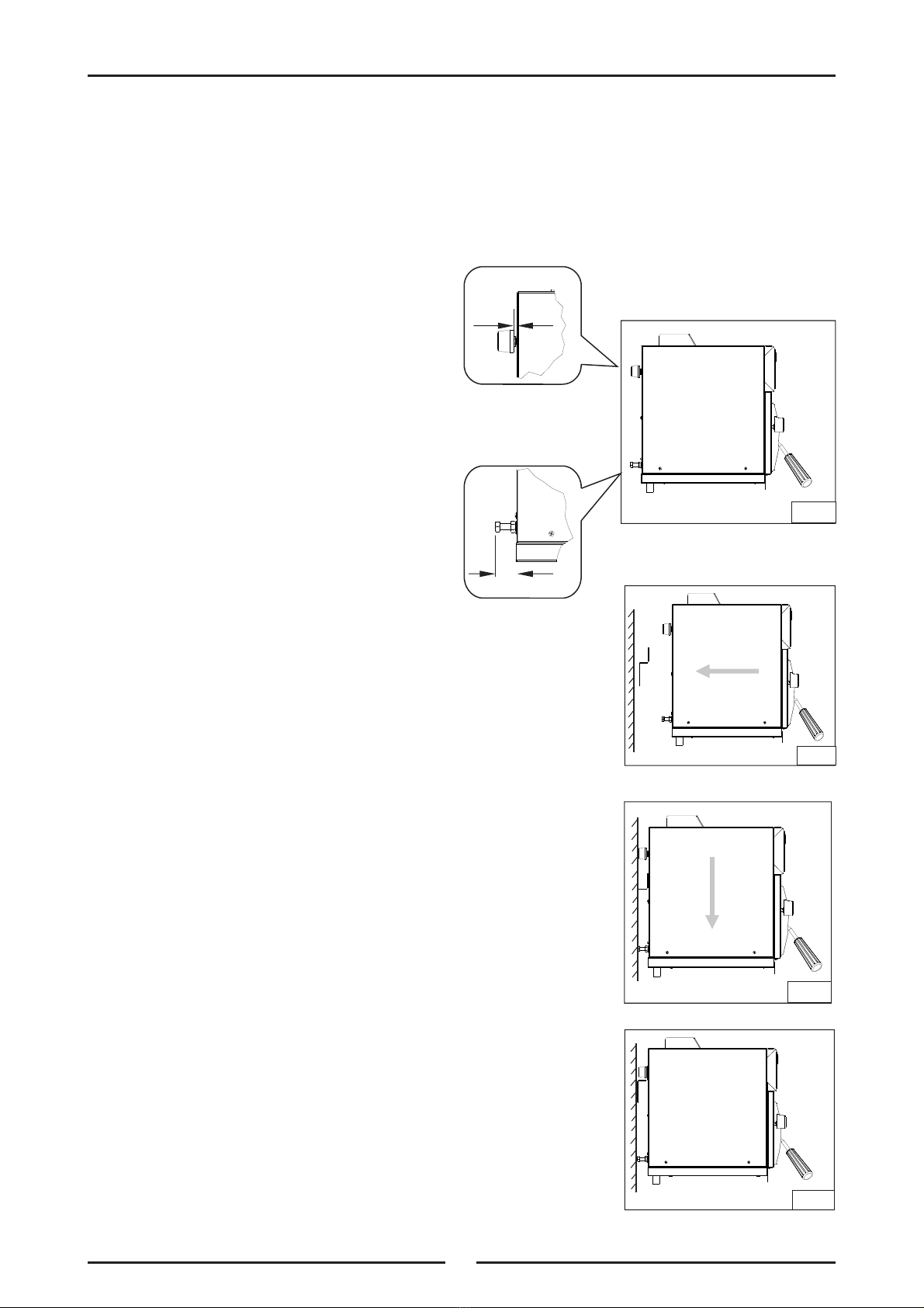
3. This appliance must be mounted onto a non-combustible wall or tailored stand, using rear wall
bracket and spacing screws provided.
4. Combustible walls must not protrude past front of appliance.
5. This appliance must not be mounted on a combustible surface or metal surface, as radiated heat will
cause these surfaces to become extremely hot.
6. Caution should be taken as intense heat is emitted at the bottom front of the appliance.
1 x Salamander Rack. 1 x Wall Mounting Bracket, including;
1 x Trough Tray. - 2 x 25 mm Black Plastic Spacers.
1 x Gas Regulator. - 2 x 3/8” Bolts / Nuts.
1 x Alternate Gas Conversion Kit.

7
Installation
7. Components having adjustments protected (e.g. paint sealed) by manufacturer are only to be
adjusted by an authorised service agent. They are not to be adjusted by the installation person.
8. The unit should be mounted under an extraction hood in compliance with all local regulations.
If the unit is not mounted under an extraction hood, the installer must ensure that all
regulations are met and that there is an unobstructed minimum distance of 750mm from top
surface of unit to ceiling, which must be of non-combustible material.
NOTE: Do not obstruct or block appliances flue. Never directly connect a ventilation system to
appliance flue outlet.
Clearances
NOTE: Only non-combustible materials can be used in close proximity to this appliance.
* We recommend a clearance of 100mm on either side of appliance to allow access to side panels for
servicing purposes.
** Using wall mounting accessories provided with this appliance.
*** Top clearances can be reduced where a local fire protection system is provided, if allowed by local
regulations.
Combustible Surface Non-Combustible Surface
Left / Right hand side 100mm 25mm (*)
Rear 50mm 30mm (**)
Top Clearance to:
- Extraction Hood 200mm
750mm- Ceiling (***)
- Grease Arresting Filter (***) 400mm }Australia / New Zealand

8
Installation
Wall Mounting (To Non-Combustible Wall Only)
1. Fix wall mounting bracket to wall with six screws, in a position where the top of bracket is level and
at least 945mm (38”) above any surface beneath unit. This will ensure that bottom of Salamander is
at least 600mm (24”) above any surface.
2. Fit two black plastic spacers to top rear
corners of unit. Leave them unscrewed by
approximately 5mm.
3. Fit two adjusting screws / bolts into nutserts
at bottom rear corners of unit. These
should protrude approximately 30mm from
rear of Salamander.
4. Lift Salamander onto wall bracket, lining up
black plastic spacers on salamander with
mounting notches in bracket.
5. Lower Salamander onto mounting bracket.
6. Tighten black spacers securely and adjust levelling
screws / bolts to ensure that unit is level.
~ 5mm
~30mm
Fig 1
Fig 2
Fig 3
Fig 4

9
Installation
Gas Connection
NOTE: ALL GAS FITTING MUST ONLY BE CARRIED OUT BY A QUALIFIED SERVICE PERSON.
1. Waldorf Salamanders do not require an electrical connection, as they function totally on gas supply
only.
2. It is essential that gas supply is correct for Salamander to be installed and that adequate supply
pressure and volume are available. The following checks should be made before installation:-
a. Gas Type appliance has been supplied for,
is shown on a coloured stickers located
above gas connection and next to rating
plate. Check that this is correct for gas
supply appliance is being installed for. Gas
conversion procedure is detailed in this
manual.
b. Supply Pressure required for this
appliance is shown in Specifications
section of this manual. Check gas supply to
ensure adequate supply pressure exists.
c. Input Rate of this appliance is stated on Rating Plate and in Specifications section of this
manual. Input rate should be checked against available supply line capacity. Particular note
should be taken if salamander is being added to an existing installation.
NOTE: It is important that adequately sized piping runs directly to connection joint on appliance
with as few tees and elbows as possible to give maximum supply volume.
3. Fit gas regulator supplied, into gas supply line as close to appliance as possible. (Refer to
Specifications section for gas supply location dimensions).
NOTE: Gas pressure regulator provided with this appliance is convertible between Natural Gas and
LPG as per ‘Gas Conversion Section’ in this manual.
Ensure regulator is converted to correct gas type that appliance will operate on.
Regulator outlet pressure is fixed ex-factory for gas type that regulator is converted to and
it is NOT to be adjusted.
Regulator connections are 1/2" BSP female.
Connection to appliance is 1/2" BSP male.
(Refer to Specifications section for gas supply location dimensions).
NOTE: A Manual Isolation Valve must be fitted to individual appliance supply line.
4. Correctly locate appliance into its final operating position.
5. Connect gas supply to appliance. A suitable jointing compound which resists breakdown action of
LPG must be used on every gas line connection, unless compression fittings are used.
6. Check all gas connections for leakages using soapy water or other gas detecting equipment.
7. Check gas operating pressure is as shown in Specifications section.
NOTE: Measure operating pressure at manifold test point with both burners operating at ‘High
Flame’ setting.
8. Turn Off mains gas supply and bleed gas out of appliance gas lines.
9. Turn On gas supply and appliance.
10. Verify operating pressure remains correct.
Rating Plate
Fig 5
DONOT USE ANAKED FLAME TO CHECK FOR GAS LEAKAGES.
Warning

10
Installation
Commissioning
1. Before leaving new installation;
a. Check the following functions in accordance with operating instructions specified in Operation
section of this manual.
Light the Main Burners.
Check the Low Fire burner operation.
Check the High Fire burner operation.
Check the Racking System operation.
b. Ensure the operator has been instructed in areas of correct lighting, operation, and shutdown
procedure for appliance.
2. This manual must be kept by owner for future reference, and a record of
Date of Purchase,
Date
of Installation
and
Serial Number of Unit
recorded and kept with this manual. (These details
can be found on Rating Plate attached to R/H side panel (refer to ‘Gas Connection’
section).
NOTE: If it is not possible to get appliance to operate correctly, shut off gas supply and contact
supplier of this unit.

11
Operation
Operation Guide
1. Waldorf Salamanders have been designed to provide simplicity of operation and 100% safety
protection.
2. Improper operation is almost impossible, however bad operation practices can reduce the life of the
salamander and produce a poor quality product. To use this salamander correctly please read the
following sections carefully:-
Lighting the Main Burners.
Racking System.
Cooking Recommendations.
Description of Controls
The salamander has individual heat controls for left and right sides. Select desired heat level and allow a
few minutes for elements to heat up.
Waldorf salamanders provide two independently controlled heat zones.
High speed grilling is provided by two infrared gas burners in ceiling of grilling compartment.
Left hand and right hand gas control knobs operate the left side and right side burners respectively,
independently of each other.
Each burner is provided with piezo ignition and flame failure protection for main burner.
Gas Control Knobs
๐OFF Position.
HIGH Flame.
LOW Flame.
Rack Handles
Fig 6
Piezo Igniter
This appliance is for professional use and is only to be used by qualified
persons.
Only authorised service persons are to carry out installation, servicing or gas
conversion operations.
Components having adjustments protected (e.g. paint sealed) by the
manufacturer should not be adjusted by the user / operator.
Caution

12
Operation
Lighting Main Burners
1. Check gas supply is turned On.
2. Depress gas control knob and rotate anti-clockwise to HIGH position.
3. With gas control knob depressed, press piezo ignition button to ignite main burner.
4. Once lit, main burner will be burning at full rate. For a lower heat, push in gas control knob and
turn fully anti-clockwise to 'LOW' position.
5. For intermediate heat, position control knob between 'HIGH' and 'LOW' positions.
6. Repeat Items 2 to 5 to light second main burner.
Turning 'Off' Main Burners
1. Depress gas control knob and rotate clockwise to 'OFF' position.
2. Main burner will extinguish.
Racking System
Rack System fitted to Salamander, when withdrawn, is self-supporting to allow easy loading of food.
Installation of rack is dependent on cooking function required.
Cooking Recommendations
1. The SN8200G Salamander has been designed to give a good evenness of heat across rack area, so
toasting, cheese melting and grilling should be relatively even wherever food is placed.
2. The HIGH position is recommended for most grilling, cheese melting functions and LOW for a
reduced heat.
3. For cooking food through rather than just surface browning, rack position three and four from the
top is recommended.
4. With Branding Plate fitted, unit is able to aid the chef in its ability to produce medium rare steaks
in the front and well done steaks at the rear - achieved with sloped Branding Plate rack position.
(Shelf 2 and 3 from top).
5. Heating Branding Plate under burners before cooking commences, also allows sealed in flavoured
goodness to be achieved.
With Branding Plate Without Branding Plate
Fig 7 Fig 8
Do not leave Salamander unattended when in use, as it does cook fast.
Caution
IMPORTANT:
Should any abnormal operation like;
- ignition problems,
- abnormal burner flame,
- burner control problems,
- partial or full loss of burner flame in normal operation, be noticed, appliance requires
IMMEDIATE service by a qualified service person and should not be used until a service is
carried out.

13
Cleaning and Maintenance
General
To achieve the best results, cleaning must be thorough, and all controls and mechanical parts
checked and adjusted periodically by a competent serviceman. If any small faults occur, have them
attended to promptly.
Don't wait until they cause a complete breakdown.
Racking
To clean this unit and racking system and to achieve the best results, it is recommended that racking
is removed completely from the unit and cleaned independently. This will allow for a more thorough
cleaning of the Salamander.
To remove racking system, carry out the following instructions.
1. Remove Trough Tray from underside of salamander unit.
2. Remove Branding Plate from rack (if fitted).
3. Slide rack out of side racks and remove from unit.
4. Remove left and right hand side racks from unit by removing single securing screw from each
of side racks.
5. Withdraw left and right hand side racks from unit.
6. Refit racking in reverse order once cleaning has been completed.
Stainless Steel Surfaces
Clean with detergent. Baked on deposits or discolouration may require a good quality stainless steel
cleaner or stainless steel wool. Always apply cleaner when Salamander is cool and rub in direction of
grain.
Vitreous Enamel Surfaces
Do not use wire brushes, steel wool or other abrasive material. Clean enamelled surfaces regularly
with a good quality domestic oven cleaner. Remove rack and side racks from Salamander - this
allows easy cleaning of flat enamelled side walls. Leave tray in to collect all residue.
Trough Tray
Empty and clean daily.
Always turn ‘Off’ gas supply before cleaning.
This appliance is not water proof.
Do not use water jet spray to clean interior or exterior of this appliance.
Caution

14
Cleaning and Maintenance
Periodic Maintenance
NOTE: All maintenance operations should only be carried out by a qualified service person.
To achieve the best results cleaning must be regular and thorough and all controls and mechanical parts
should be checked and adjusted periodically by a qualified service person. If any small faults occur, have
them attended to promptly. Don't wait until they cause a complete breakdown. It is recommended that
the appliance is serviced every 6 months.
Gas Control Valve Re-Greasing
Gas control valve should be dismantled and greased every 6 months to ensure correct operation.
To carry out this operation;-
a. Remove gas control knobs from gas tap spindles by pulling
knobs away from control panel.
b. Remove drip tray from appliance.
c. Remove two screws on underside of control panel, securing
control panel to hob.
d. Remove control panel from front of appliance.
e. Remove 2 screws holding shaft plate to gas control body and
remove control shaft and plate. (See Fig 9). Note orientation
of shaft for correct re-assembly.
f. Using needle nose pliers or similar, pull out gas control
spindle, again noting its orientation.
g. Apply a suitable high temperature gas cock grease or
lubricant such as ROCOL - A.S.P (Anti scuffing
paste) / Dry Moly Paste to outside of spindle. (See
Fig 10).
h. Replace spindle and re-assemble gas control valve
in reverse order.
i. Refit control panel to appliance and secure with 2
screws.
j. Refit knobs to gas control valve spindles.
Spindle
Two Screws Fig 9
Fig 10

15
Fault Finding
This section provides an easy reference guide to the more common problems that may occur during
operation of your equipment. The fault finding guide in this section is intended to help you correct, or at
least accurately diagnose problems with your equipment.
Although this section covers the most common problems reported, you may encounter a problem not
covered in this section. In such instances, please contact your local authorised service agent who will
make every effort to help you identify and resolve the problem. Please note that the service agent will
require the following information:-
Model Code and Serial Number of appliance. (both can be found on Rating Plate located on
appliance.
Fault Possible Cause Remedy
Main Burner goes out when gas
control knob released.
Releasing knob before thermocouple has
heated.
Main Burner flame too small:-
- Gas pressure too low.
- Partially blocked main injector.
Thermocouple faulty.
Hold knob in for at least 20 seconds
following ignition of main burner.
Call service provider.
Main burners will not light.
No gas supply.
Incorrect supply pressure.
Blocked main injector.
Faulty gas control.
Ensure gas isolation valve is turned on,
and that bottles are not empty.
Call service provider.
Burner goes out.
Check main burner flame is touching
thermocouple.
Interruption in gas supply to burner.
Main injector size too small.
(See Specifications section).
Call service provider.
Lack of glowing.
Large haze beneath burner. Check gas pressure at pressure test point. Call service provider.
Burner blow-back. Gas leak in burner plaque.
(See Servicing Section).
New burner plaque required.
Call service provider.

16
Gas Conversion and Specifications
Conversion Procedure
NOTE:
These conversions should only be carried out by qualified persons. All connections must
be checked for leaks before re-commissioning the appliance.
For all the following conversion instructions, the side access panels have to be removed
(Remove two screws at bottom of each side panel).
All conversion details apply to both L/Hand and R/Hand burners.
For all relevant gas specifications refer to the table at the end of this section.
Main Burner Injectors
1. Remove the following:-
Two side access panels.
Main burner injectors.
2. Remove main burner injectors and replace with correct size
injectors as shown in ‘Gas Specifications’ tables at rear of this
section.
Low Fire Adjustment
1. Remove the following:-
Gas control knobs from front of unit.
Two front control panels.
2. Light main burners and check flame size on Low position.
Adjust burner gas control valve low fire adjustment screw as
shown in ‘Gas Specifications’ tables at rear of this section.
NOTE: ‘Low Fire Screw’ should be sealed with coloured paint on
completion of low fire adjustment.
3. Refit the following:-
Two side access panels.
Two front control panels.
Gas control knobs.
Main Burner
Injector
Low Fire
Adjustment
Ensure Appliance is isolated from gas supply before commencing servicing.
Caution

17
Gas Conversion and Specifications
Gas Regulator
NOTE: Gas regulator supplied is
convertible between Natural Gas
and LP Gas, but it’s outlet
pressure is fixed ex-factory and
is NOT to be adjusted.
Gas Type Labels
On completion of gas conversion, replace gas type labels located at:-
- Rear of unit, above gas connection.
- Beside rating plate.
Commissioning
Before leaving installation;
1. Check all gas connections for leakage using soapy water or other gas detecting equipment.
2. Carry out a Commissioning check of appliance as shown in Installation Section of this manual.
3. Ensure any adjustments done to components that have adjustments / settings paint sealed are to be
re-sealed.
NOTE: If for some reason it is not possible to get appliance to operate correctly, shut Off gas
supply and contact supplier of this appliance.
NOTE, Pin rotated
for Natural Gas
NOTE, Pin rotated
for LPG
DONOT USE ANAKED FLAME TO CHECK FOR GAS LEAKAGES.
Warning

18
Gas Conversion and Specifications
Gas Specifications
- Non CE Only (Australia / New Zealand):
- CE Only:
NOTE: * Measure burner operating pressure at manifold test point with both burners operating at
full setting. Operating pressure is ex-factory set and not to be adjusted, apart from when
converting between gases, if required. (Refer to ‘Gas Conversion’ section for details).
Natural Gas (G20) Propane (G31)
Main Burner Injectors Ø 1.85mm Ø 1.15mm
Low Fire: Size Ø 1.00mm Ø 1.00mm
Adjustment 2 turns out (c.c.w.) ½ turn out (c.c.w.)
Operating Pressure 10 mbar (*) 26 mbar
Gas Regulator Cap Screw
Supply Pressure 20 mbar 37 mbar
Natural Gas LP Gas
Main Burner Injectors Ø 1.85mm Ø 1.15mm
Low
Fire
Size Ø 1.00mm Ø 1.00mm
Adjustment 2 turns out (c.c.w.) ½ turn out (c.c.w.)
Operating Pressure 1.0 kPa (*) 2.55 kPa (*)
Gas Regulator Cap Screw
Supply Pressure 1.13 - 3.4 kPa 2.75 - 4.5 kPa
This manual suits for next models
2
Table of contents
Other Waldorf Grill manuals
Popular Grill manuals by other brands

Pyle
Pyle Nutrichef PKCHMT18 user manual

Broil King
Broil King SSG-36-1 Installation instructions and owner's manual

George Foreman
George Foreman GRP100 Series Use and care book

George Foreman
George Foreman GR1100GM Use and care book

Salton
Salton George Foreman GIPOD200 owner's manual

Weber
Weber Genesis 6721001 owner's guide

Fritel
Fritel TG 3570 instruction manual

Outback
Outback Cook Dome 571 Assembly and operating instructions

Dansons Group
Dansons Group Pit Boss Competition PB1230CS1 owner's manual

VonHaus
VonHaus 2500546 instruction manual

Coleman
Coleman 9930 Series Instructions for use

Koolatron
Koolatron Total Chef owner's manual