Waldorf RN8813G User manual

1
Installation and Operation Manual
Series
RN8510G
RN8610G
RN8810G
Gas Static Oven Range
Date Purchased
Serial Number
Dealer
Service Provider
228681-9
For use in GB & IE

The reproduction or copying of any part of this manual by any means whatsoever is strictly forbidden unless authorized previously in
writing by the manufacturer.
In line with policy to continually develop and improve its products, Moffat Ltd. reserves the right to change the specifications and
design without prior notice.
© Copyright Moffat Ltd. August 2008.
MANUFACTURED BY
Moffat Limited
PO Box 10001
Christchurch
New Zealand
Ph: (03) 389 1007
Fax: (03) 389 1276
WORLD-WIDE BRANCHES
UNITED KINGDOM
Blue Seal
67 Gravelly Business Park
Gravelly Park
Birmingham
West Midlands
B24 8TQ
Ph: (121) 327 5575
Fax: (121) 327 9711
UNITED STATES
Moffat Inc
3765 Champion Blvd
Winston-Salem
North Carolina 27115
Ph: (336) 661 0257
Fax: (336) 661 9546
CANADA
Serve Canada
22 Ashwarren Road
Downview
Ontario M3J1Z5
Toll Free:800 263 1455
Ph: (416) 631 0601
Fax: (416) 631 0315
www.servecanada.com
www.moffat.com
NEW ZEALAND
Christchurch Auckland
Moffat Limited Moffat Limited
PO Box 10-001 4 Waipuna Road
16 Osborne Street Mt Wellington
Christchurch Auckland
Ph: (03) 389 1007 Ph: (09) 574 3150
Fax: (03) 389 1276 Fax: (09) 574 3159
AUSTRALIA
Victoria New South Wales
Moffat Pty Limited Moffat Pty Limited
740 Springvale Road 3/142 James Ruse Drive, Rose Hill
Mulgrave, Melbourne PO Box 913, Smithfield
Victoria 3171 Sydney, N.S.W. 2142
Ph: (03) 9518 3888 Ph: (02) 8833 4111
Fax: (03) 9518 3838 Fax: (02) 8833 4133
Western Australia Queensland
Moffat Pty Limited Moffat Pty Limited
67 Howe Street 30 Prosperity Place
Osbourne Park Geebung, Brisbane
WA 6017 Queensland 4034
Ph: (08) 9202 6820 Ph: (07) 3630 8600
Fax: (08) 9202 6836 Fax (07) 3630 8623

1
Waldorf Gas Static Oven Range
RN8510G Gas Static Oven Range - 750mm wide.
RN8610G Gas Static Oven Range - 900mm wide.
RN8810G Gas Static Oven Range - 1200mm wide.
Introduction .............................................................................................. 2
Specification .............................................................................................. 3
Model Numbers Covered in this Specification
General
Gas Supply Requirements
Gas Connection
Dimensions ................................................................................................ 5
Installation ................................................................................................ 8
Installation Requirements
Unpacking
Location
Clearances
Assembly
Gas Connection
Commissioning
Operation ................................................................................................. 11
Operation Guide
Description of Controls
Open Burners
Griddle
Oven Pilot Ignition
Oven - Main Burner / Thermostat
Turning the Oven to ‘Stand-By’ (Pilot ‘ON’ Only)
Oven ‘Shut Down’
Cleaning and Maintenance ...................................................................... 15
General
After Each Use
Daily Cleaning
Weekly Cleaning
Periodic Maintenance
Fault Finding............................................................................................ 19
Gas Conversion and Specifications.......................................................... 20
Conversion Procedure
Gas Specifications
Replacement Parts List............................................................................ 27
Contents

2
Introduction
We are confident that you will be delighted with your WALDORF GAS STATIC OVEN RANGE and it will
become a most valued appliance in your commercial kitchen.
To ensure you receive the utmost benefit from your new Waldorf appliance, there are two
important things you can do.
Firstly:
Please read the instruction book carefully and follow the directions given. The time taken will be well
spent.
Secondly:
If you are unsure of any aspect of the installation, instructions or performance of your appliance,
contact your WALDORF dealer promptly. In many cases a phone call could answer your question.
CE Only:
These instructions are only valid if the country code appears on the appliance. If the code does not
appear on the appliance, refer to the supplier of this appliance to obtain the technical instructions for
adapting the appliance to the conditions for use in that country.
WARNING:
IMPROPER INSTALLATION, ADJUSTMENT, ALTERATION, SERVICE OR MAINTENANCE CAN CAUSE PROPERTY
DAMAGE, INJURY OR DEATH. READ THE INSTALLATION, OPERATING AND MAINTENANCE INSTRUCTIONS
THOROUGHLY BEFORE INSTALLING OR SERVICING THIS APPLIANCE.
WARNING:
INSTRUCTIONS TO BE FOLLOWED IN THE EVENT THE USER SMELLS GAS ARE TO BE POSTED IN APROMINENT
LOCATION. THIS INFORMATION SHALL BE OBTAINED BY CONSULTING THE LOCAL GAS SUPPLIER.
WARNING:
GREAT CARE MUST BE TAKEN BY THE OPERATOR TO USE THE EQUIPMENT SAFELY TO GUARD IT AGAINST RISK
OF FIRE.
• THE APPLIANCE MUST NOT BE LEFT ON UNATTENDED.
• ITIS RECOMMENDED THAT AREGULAR INSPECTION IS MADE BY ACOMPETENT SERVICEMAN TO ENSURE
CORRECT AND SAFE OPERATION OF YOUR APPLIANCE IS MAINTAINED.
• DO NOT STORE OR USE GASOLINE OR OTHER FLAMMABLE VAPOURS OR LIQUIDS IN THE VICINITY OF
THIS OR ANY OTHER APPLIANCE.
• DO NOT SPRAY AEROSOLS IN THE VICINITY OF THIS APPLIANCE WHILE IT IS IN OPERATION.
C
AUTION
:
This appliance is;
•
For professional use and is to be used by qualified persons only.
•
Only qualified service persons are to carry out installation, servicing and
gas conversion operations.
•
Components having adjustments protected (e.g. paint sealed) by the
manufacturer should not be adjusted by the user / operator.
•
DO NOT operate the appliance without the legs supplied fitted.

3
Specifications
Model Numbers Covered in this Specification
RN8510G[1] Gas Static Oven + 4 Open Burners.
RN8513G[1] Gas Static Oven + 2 Open Burners + 300 mm Griddle.
RN8610G[1] Gas Static Oven + 6 Open Burners.
RN8613G[1] Gas Static Oven + 4 Open Burners + 300 mm Griddle.
RN8616G[1] Gas Static Oven + 2 Open Burners + 600 mm Griddle.
RN8619G Gas Static Oven + 900 mm Griddle.
RN8810G[1] Gas Static Oven + 8 Open Burners + 900 mm + Storage Cabinet.
RN8813G[1] Gas Static Oven + 6 Open Burners + 300 mm Griddle + Storage Cabinet.
RN8816G[1] Gas Static Oven + 4 Open Burners + 600 mm Griddle + Storage Cabinet.
RN8819G[1] Gas Static Oven + 2 Open Burners + 900 mm Griddle + Storage Cabinet.
[1] - Open Burner Options;
F - With Flame Failure Protection.
PF - With Pilot and Flame Failure Protection.
General
A heavy duty, general purpose gas range created for compact modular kitchens. It has a high option
Cook Top / Griddle arrangement and is available on industrial adjustable feet or on robust rollers.
Open Burners are available in either 'PF' (Pilot and Flame Failure) or 'F' (Flame Failure Only) options.
Open Burner and Griddle options are fitted with individual flame failure for each open burner.
Griddles are fitted with pilot, flame failure and piezo ignition as standard. Easy clean stainless steel
external finish.
The oven is fitted with pilot and flame failure with piezo ignition and a 30MJ oven burner.

4
Specifications
Gas Supply Requirements
- Australia / New Zealand Only:
- UK Only
Appliance Classification
Category: II2H3P.
Flue Type: A1.
(*) The burner operating pressure is to be measured at the manifold test point with two burners
operating at full setting. The operating pressure is ex-factory set, through the appliance
regulator and is not to be adjusted, apart from when carrying out gas conversion, if required.
(Refer to the ‘Gas Conversion’ section for details).
Gas Connection
Gas supply connection point is located at the rear of the appliance, approximately 130 mm from the
right hand side, 35 mm from the rear and 655 mm from the floor and is reached from beneath the
appliance. (Refer to the ‘Dimensions’ section).
Connection is ¾" BSP male thread.
Natural Gas (G20) Propane (G31)
Open Burner
(each)
Griddle
(each 300mm section) Oven Open Burner
(each)
Griddle
(each 300mm section) Oven
Heat Input
(nett)
Nominal 6.5 kW 5.5 kW 8.0 kW 6.5 kW 5.5 kW 8.0 kW
Reduced 1.75 kW 1.85 kW 2.4 kW 1.75 kW 1.95 kW 2.4 kW
Gas Rate
(nett)
Nominal 0.69 m3/hr 0.58 m3/hr 0.85 m3/hr 0.51 kg/hr 0.43 kg/hr 0.62 kg/hr
Reduced 0.19 m3/hr 0.20 m3/hr 0.25 m3/hr 0.14 kg/hr 0.15 kg/hr 0.19 kg/hr
Supply Pressure 20 mbar 37 mbar
Operating Pressure 9.5 mbar 26 mbar
Gas Connection 3/4” B.S.P. Male
Natural Gas LP Gas (Propane)
Input Rate (N.H.G.C.)
- each Open Burner
28 MJ/hr
(26,540 Btu/hr)
28 MJ/hr
(26,540 Btu/hr)
- each 300 mm Griddle Section 21 MJ/hr
(19,900 Btu/hr)
21 MJ/hr
(19,900 Btu/hr)
- Oven 30 MJ/hr
(28,434 Btu/hr)
30 MJ/hr
(28,434 Btu/hr)
Supply Pressure 1.13 - 3.40 kPa
(4.5” - 13.5” w.c.)
2.75 - 4.50 kPa
(11” - 18” w.c.)
Burner Operating Pressure 0.95 kPa (*)
(3.7” w.c.)
2.6 kPa (*)
(10” w.c.)
Gas Connection 3/4” B.S.P. Male

5
Dimensions
RN8510G
Cook Top Options
RN8510G RN8513G

6
Dimensions
RN8610G
Cook Top Options
RN8610G RN8613G
RN8616G RN8619G

7
Dimensions
RN8810G
Cook Top Options
RN8810G RN8813G
RN8816G RN8819G

8
Installation Requirements
NOTE:
• It is most important that this appliance is installed correctly and that operation is correct
before use. Installation shall comply with local gas and health and safety requirements.
• This appliance shall be installed with sufficient ventilation to prevent the occurrence of
unacceptable concentrations of health harmful substances in the room, the appliance is
installed in.
Waldorf Static Oven Ranges are designed to provide years of satisfactory service, and correct installation is
essential to achieve the best performance, efficiency and trouble-free operation.
This appliance must be installed in accordance with National installation codes and in addition, in
accordance with relevant National / Local codes covering gas and fire safety.
AUSTRALIA: - AS 5601 - Gas Installations.
NEW ZEALAND: - NZS 5261 - Gas Installation.
UNITED KINGDOM: - Gas Safety (Installation & Use) Regulations 1998.
- BS 6173 - Installation of Catering Appliances.
- BS 5440 1 & 2 - Installation Flueing & Ventilation.
IRELAND: - IS 820 - Non - Domestic Gas Installations.
Installations must be carried out by qualified persons only. Failure to install equipment to the
relevant codes and manufacturer’s specifications shown in this section will void the
warranty.
Components having adjustments protected (e.g. paint sealed) by the manufacturer are only
to be adjusted by an authorised service agent. They are not to be adjusted by the installation
person.
Unpacking
• Remove all packaging and transit protection from the appliance including all protective plastic
coating from the exterior stainless steel panels.
• Check equipment and parts for damage. Report any damage immediately to the carrier and
distributor.
• Report any deficiencies to the distributor who supplied the appliance.
• Check that the available gas and electrical supply is correct to that shown on the rating plate located
on the front right hand corner of the bottom sill.
Location
1. Installation must allow for a sufficient flow of fresh air for the combustion air supply.
2. Installation must include adequate ventilation means, to prevent dangerous build up of combustion
products.
3. Never directly connect a ventilation system to the appliance flue outlet.
4. Any gas burning appliance requires adequate clearance and ventilation for optimum and
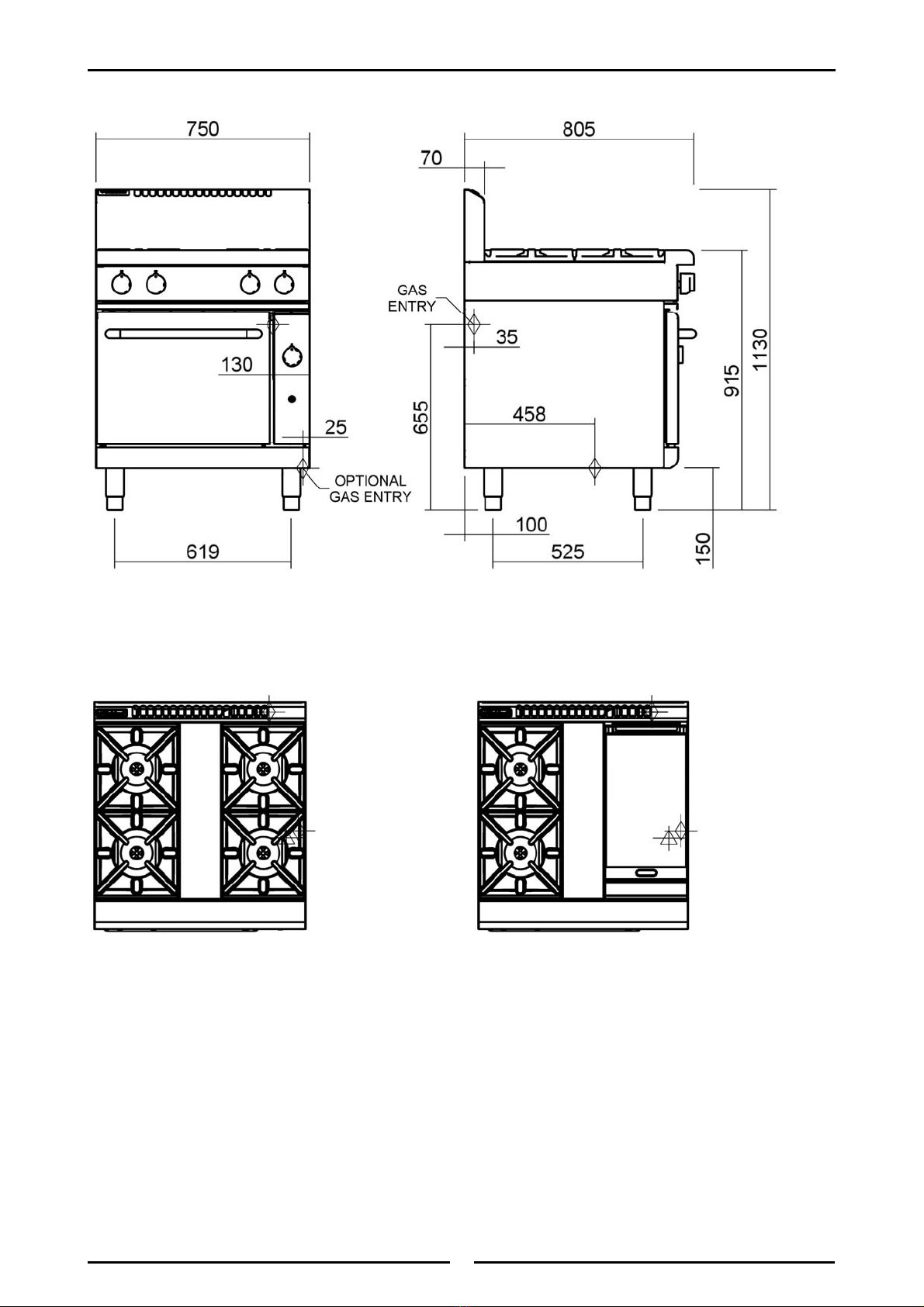
trouble-free operation. The minimum installation clearances shown below are to be adhered to.
5. Position the appliance in its approximate working position.
6. All air for burner combustion is supplied from underneath the appliance. The legs must always be
fitted and no obstructions placed on the underside or around the base of the appliance, as
obstructions will cause incorrect operation and/or failure of the appliance.
NOTE: Do not obstruct or block the appliances flue. Never directly connect a ventilation system to
the appliance flue outlet.
Installation
Combustion Air Requirements:
RN8510G RN8610G RN8810G
Natural Gas (G20) 33 m3/hr 45 m3/hr 57 m3/hr
LPG / Propane(G31) 34 m3/hr 47 m3/hr 59 m3/hr

9
Clearances
NOTE: Only non-combustible materials can be used in close proximity to this appliance.
* Side clearances can be 50 mm when the adjacent surface is at least 100 mm below the cooking
surface.
Assembly
NOTE:
• All Models are delivered completely assembled. No further assembly is required.
• This appliance is fitted with adjustable feet to enable the appliance to be positioned
securely and level. This should be carried out on completion of the gas connection. Refer
to the ‘Gas Connection’ section.
Optional Accessories (Refer to Replacement Parts List)
• Rear Roller Kit. For installation details, refer to the instructions supplied with each kit.
• Plinth Kit. For installation details, refer to the instructions supplied with each kit.
1. Check that all the feet (or castors) are securely fitted.
2. Adjust the four feet to make the Range steady and level.
Gas Connection
NOTE: ALL GAS FITTING MUST ONLY BE CARRIED OUT BY AN QUALIFIED PERSON.
1. Waldorf Ranges do not require an electrical connection, as they function totally on the gas supply
only.
2. It is essential that the gas supply is correct for the appliance to be installed and that adequate
supply pressure and volume are available. The following checks should therefore be made before
installation:-
a. Gas Type the appliance has been supplied for, is shown
on coloured stickers located above the gas connection
point and rating plate. Check that this is correct for the
gas supply the appliance is being installed for. The gas
conversion procedure is detailed in this manual.
b. Supply Pressure required for this appliance is shown in
the “Specifications” section of this manual. Check the gas
supply to ensure adequate supply pressure exists.
c. Input Rate of this appliance is stated on the Rating Plate
and in the ‘Specifications’ section of this manual. The input
rate should be checked against the available gas supply
line capacity. Particular note should be taken if the
appliance is being added to an existing installation.
NOTE: It is important that adequately sized piping runs directly to the connection joint on the
appliance with as few tees and elbows as possible to give maximum supply volume.
3. Fit the gas regulator supplied, into the gas supply line as close to the appliance as possible.
NOTE: The gas pressure regulator provided with this appliance is convertible between Natural Gas
and LPG as per the ‘Gas Conversion Section’ in this manual.
Ensure the regulator is converted to the correct gas type that the appliance will operate on.
The regulator outlet pressure is fixed ex-factory for the gas type that the
regulator is converted to and it is NOT to be adjusted.
Installation
Fig 1
Rating Plate will be
located in this Area
Combustible Surface Non Combustible Surface
Left/Right hand side 250 mm (*) 0 mm
Rear 100 mm 0 mm

10
The regulator connections are 3/4" BSP female.
The connection to the appliance is 3/4" BSP male.
(Refer to the “Specifications” section for the gas supply location dimensions).
NOTE: A Manual Isolation Valve must be fitted to the individual appliance supply line.
4. Correctly locate the appliance into its final operating position and using a spirit level, adjust the legs
so that the appliance is level and at the correct height.
5. Connect the gas supply to the appliance. A suitable joining compound which resists the breakdown
action of LPG must be used on every gas line connection, unless compression fittings are used.
6. Check all gas connections for leakages using soapy water or other gas detecting equipment.
7. Check that the gas operating pressure is as shown in “Specifications” section.
NOTE: The operating pressure to be measured at the manifold test point and with 2 burners
operating at the “High Flame” setting.
8. Turn off the mains gas supply and bleed the
gas out of the appliance gas lines.
9. Turn on the gas supply and the appliance.
10. Verify that the operating pressure remains
correct.
Commissioning
1. Before leaving the new installation;
a. Check the following functions in accordance with the operating instructions specified in the
‘Operation’ section of this manual.
• Lighting the Griddle.
• Lighting the Open Burners (F - Flame Failure Option).
• Lighting the Open Burners (PF - Pilot and Flame Failure Option).
• Check the Low Fire burner operation.
• Light the Oven Pilot and Main Burners.
• Check the Oven Main Burner Thermostat operation.
• Turning the Oven to ‘Stand-By’ Mode.
• Oven ‘Shut Down’.
b. Ensure that the operator has been instructed in the areas of correct lighting, operation, and
shutdown procedure for the appliance.
2. This manual must be kept by the owner for future reference, and a record of the
Date of
Purchase,
Date of Installation
and
Serial Number of the Appliance
recorded and kept with
this manual. (These details can be found on the Rating Plate attached to the bottom right
hand corner of the bottom sill. Refer to the ‘Gas Connection’ section).
NOTE: If for some reason it is not possible to get the appliance to operate correctly, shut off the
gas supply and contact the supplier of this appliance.
Installation
WARNING:
DONOT USE ANAKED FLAME TO CHECK FOR GAS LEAKAGES.
Manifold
Test Point
Fig 2

11
Operation Guide
1. Waldorf appliances have been designed to provide simplicity of operation and 100% safety
protection.
2. Improper operation is therefore almost impossible, however bad operation practices can reduce the
life of the appliance and produce a poor quality product. To use this appliance correctly please read
the following sections carefully:-
• Lighting the Open Burners (F - Flame Failure Option).
• Lighting the Open Burners (PF - Pilot and Flame Failure Option).
• Lighting the Griddle.
• Oven Pilot Ignition.
• Oven Main Burner / Thermostat.
• Turning the Oven to ‘Stand-By’ Mode.
• Oven ‘Shut-Down’.
Description of Controls
Operation
Griddle Option
Burner Control
OFF Position
PILOT Burner
HIGH Flame
LOW Flame
Gas Control Knobs
Piezo Igniter
(Griddles Only)
Piezo Igniter (Oven)
Oven Option
OFF Position
PILOT Burner
Temperature
Graduations 100°C to
290°C
Fig 3
Open Burner Option
OFF Position
HIGH Flame
LOW Flame
Rear Burner
Front Burner
(Indicators are located
above the Gas Control
Knobs).
C
AUTION
:
•
This appliance is for professional use and is only to be used by qualified
people.
•
Only qualified service persons should be used to carry out installation,
servicing or gas conversion operations.
•
Components having adjustments protected (e.g. paint sealed) by the
manufacturer should not be adjusted by the user/operator.

12
Open Burners
NOTE: Only cooking pans from size Ø 150mm to Ø 420mm are suitable fo use on these open
burners.
Flame Failure Option (F-Models)
Lighting the Open Burners
Flame Failure Protection is incorporated for each burner by way of a thermo-electric system which
will shut off the gas supply to that burner in the event that the burner goes out, so that un-burnt gas
is not expelled.
a. Select the burner required, depress and turn the corresponding gas control knob anti-clockwise to
the ‘HIGH’ position.
b. With the gas control knob depressed, manually light the burner.
c. Release the gas control knob after approximately 10-20 seconds after lighting the burner.
d. The burner should stay alight - if not, repeat Steps (a to (c above.
e. To achieve simmer control, depress the gas control knob and rotate between the ‘HIGH’ and
‘LOW’ positions to achieve the temperature required.
Turning 'OFF' the Open Burners
a. When the main burner is not required, depress and turn the gas control knob clockwise back to
the ‘OFF’ position. The 'MAIN' burner will extinguish.
Pilot and Flame Failure Option (PF-Models)
Lighting the Open Burners
These hobs are fitted with individual standing pilots for each open burner which allows the main
burners to be turned 'ON' - 'OFF' without the need to manually re-light the burner each time that it is
turned 'ON', as the burner will automatically light itself off the pilot burner.
Flame Failure Protection is incorporated for each burner by way of a thermo-electric system which
will shut off the gas supply to that burner in the event that the burner goes out, so that un-burnt gas
is not expelled.
a. Select the burner required, depress and turn the corresponding gas control knob anti-clockwise to
the ‘PILOT’ position.
b. With the gas control knob depressed, manually light the pilot burner.
c. Release the gas control knob after approximately 10-20 seconds after lighting the pilot burner.
d. The pilot burner should stay alight - if not, repeat Steps (a to (c above.
e. ‘Full Flame’ can now be achieved by depressing and rotating the gas control knob anti-clockwise
to the first stop 'HIGH' flame position.
f. Low flame can be achieved by depressing the gas control knob and rotating fully anti-clockwise
to the ‘LOW' flame position.
g. To achieve simmer control, depress the gas control knob and rotate between the ‘HIGH’ and
‘LOW’ positions to achieve the temperature required.
Turning 'OFF' the Open Burners / Pilots
a. To turn 'OFF' the main burner, but keep the pilot burner alight, rotate the gas control knob to the
'PILOT' position. The main burner will extinguish and the pilot will remain alight.
b. To turn 'OFF' the 'PILOT', depress and turn the gas control knob clockwise back to the ‘OFF’
position. The 'PILOT' burner will extinguish.
Operation

13
Griddle
Lighting the Griddle
a. Depress the gas control knob and rotate anti-clockwise to the ‘PILOT’ position.
b. With the gas control knob depressed, press the piezo ignition button to ignite the pilot burner.
Repeat Items 1 to 2 until the pilot is lit.
c. Release the gas control knob approximately 10-20 seconds after lighting the pilot.
d. The pilot should now remain alight - if not, repeat Steps (a to (c above.
e. ‘Full Flame’ can now be achieved by depressing and rotating the gas control knob anti-clockwise
to the first stop.
f. Low flame can be achieved by depressing the gas control knob and rotating fully anti-clockwise
to the ‘Low Flame’ position.
g. When the main burner is not required, depress and turn the gas control knob clockwise back to
the ‘OFF’ position.
Turning 'OFF' the Griddle Burner / Pilot
a. To turn 'OFF' the griddle, but keep the pilot burner alight, rotate the gas control knob to the
'PILOT' position. The griddle burner will extinguish and the pilot will remain alight.
b. To turn 'OFF' the 'PILOT', depress and turn the gas control knob clockwise back to the ‘OFF’
position. The 'PILOT' burner will extinguish.
Operation
C
AUTION
:
The griddle plate temperature reaches over 300°C in hottest points during
normal operation at 'Full Flame' setting.

14
Oven Pilot Ignition
This oven is fitted with a pilot as a standard option and flame failure protection, which is incorporated by
way of a thermo-electric system for the main burner. Flame failure protection will shut off the gas supply
to the burner in the event that the pilot burner goes out, so that un-burnt gas is not expelled.
This is an
important safety feature which is slowly becoming law throughout the world
.
1. Open the oven door. Depress the thermostat control
knob and rotate anti-clockwise to the ‘PILOT’ position.
2. While holding the thermostat control knob depressed,
press the piezo ignition button to ignite the oven pilot
burner. Repeat Items 1 to 2 until the oven pilot is lit.
3. View the oven pilot burner through the hole in the front
of the sole plate with the oven door open.
4. Release the thermostat control knob approximately 10-20
seconds after lighting the pilot.
5. The pilot should now remain alight - if not, repeat Steps
2 to 4 above.
Oven Main Burner / Thermostat
1. With the pilot burner alight, rotate the oven thermostat control knob to the desired oven
temperature setting, this will regulate the gas supply to the oven burner and the oven main burner
will light from the pilot burner.
2. To turn the main burner ‘OFF’, simply turn the thermostat control knob to the ‘OFF’ position.
Turning the Oven to ‘Standby’ (Pilot ‘ON’ Only)
To turn off the oven burner / heating, set the oven thermostat control knob to the ‘PILOT’ position,
this will turn the oven ‘OFF’, but leave the oven pilot burner ‘ON’. In this position the pilot burner
will remain alight, but the main burner will not operate until the oven thermostat control knob is set
to a temperature.
Oven ‘Shut-Down’
To ‘Shut Down’ the oven, turn the oven thermostat control knob to the ‘OFF’ position. This will turn
‘OFF’ the oven and extinguish the pilot burner. To relight the pilot burner, refer to ‘Oven Pilot
Ignition’ in this section.
Operation
Pilot Burner
viewing holes
Fig 4
! IMPORTANT DO NOT USE aluminium foil or trays directly on the cast iron sole plate(s).
NEVER block or cover the openings on each side of the sole plate(s).
Should any abnormal operation like;
- ignition problems,
- abnormal burner flame,
- burner control problems,
- partial or full loss of burner flame in normal operation, be noticed, the appliance requires
IMMEDIATE service by a qualified service person and should not be used until such service is
carried out.
IMPORTANT

15
General
Clean the range regularly. A clean range looks better, will last longer and will perform better.
Carbonised grease on the surface or between the trivets, griddle plates will hinder the transfer of
heat from the cooking surface to the food. This will result in loss of cooking efficiency.
NOTE: Each griddle option can be supplied with a scraper tool and a pack of blades for cleaning
the griddle surface. These are not supplied with the griddle and have to be purchased
separately. Refer to the 'Replacement Parts List' at the rear of this manual.
DO NOT use water on the trivets, burners and griddle plates while these items are still
hot as warping and cracking may occur. Allow these items to cool down and then
remove for cleaning. The entire trivets, griddle plates and burner caps can be removed for
cleaning.
NOTE:
• DO NOT use abrasive detergents, strong solvents or caustic detergents as they could
corrode or damage the range.
• In order to prevent the forming of rust on the trivets, griddle plates (If fitted) and burners,
ensure that any detergent or cleaning material has been completely removed after each
cleaning. The appliance should be switched on briefly to ensure that the griddle plates
become dry. Oil or grease should be spread over the griddle surface in order to form a thin
protective greasy film.
To keep your range clean and operating at peak efficiency, follow the procedures shown below:-
After Each Use
1. Clean the griddle with a scraper tool to remove any food debris.
2. Always ensure that the scraper tool blades are changed regularly to ensure that the scraper tool
works efficiently and prevents damage to the griddle plate surface.
3. Clean the range castings with a stiff nylon brush or a flexible spatula to remove any food debris.
Cleaning and Maintenance
C
AUTION
:
Always turn off the gas supply before cleaning.
This appliance is not water proof.
Do not use water jet spray to clean interior or exterior of this appliance.
WARNING:
THE BLADES FITTED TO THE SCRAPER TOOL ARE EXTREMELY SHARP AND ARE TO BE USED WITH CARE.
C
AUTION
:
Always ensure that an even pressure is applied over the whole surface of the
scraper tool when using on the flat surface of the griddle, to prevent scoring of
the surface.
NEVER bang the sharp edge of the scraper tool on the flat surface of the
griddle as this will damage the finish and invalidate the warranty.

16
Cleaning and Maintenance
Daily Cleaning
1. The grease / spill tray(s) should be checked and emptied frequently to prevent overflow and
spillage. Remove the grease / spill tray(s) while still warm so that the grease is in a liquid state.
Empty any grease from the trays and wash thoroughly in the same manner as any cooking utensil.
2. Remove the burner caps and bases, the trivets and thoroughly clean the splash back, interior and
exterior surfaces of the range with hot water, a detergent solution and a soft scrubbing brush.
3. Brush the griddle surface (optional - if fitted) with a soft bristled brush. Any carbon deposits should
be removed using a scraper tool followed by wiping with a cloth to prevent accumulation of food
deposits.
4. Dry the range thoroughly with a dry cloth and polish with a soft dry cloth.
Weekly Cleaning
NOTE:
• If the range usage is very high, we recommend that the weekly cleaning procedure is
carried out on a more frequent basis.
• Ensure that protective gloves are worn during the cleaning process.
• DO NOT use harsh abrasive detergents, strong solvents or caustic detergents as they will
damage the range, burners and plates.
• DO NOT use water on the trivets, griddle plates and burners while they are still hot as
cracking may occur. Allow these items castings to cool and remove for cleaning.
• DO NOT clean the burners in a dishwasher.
Range Cooking Area
a. Clean the range cooking area using a soft cloth moistened with a mild detergent and hot water
solution.
b. Baked on deposits or discolouration may require a good quality stainless steel cleaner or stainless
steel wool. Always apply cleaner when the appliance is cold and rub in the direction of the grain.
c. It should not be necessary to remove the splash guards covering the burner manifolds for
cleaning purposes. These can be cleaned in situ.
d. Remove the grease tray and clean with a mild anti bacterial detergent and hot water solution
using a soft bristled brush.
e. Dry the grease tray thoroughly with a dry cloth.
Griddle Plate - (Steel)
NOTE: In order to prevent the forming of rust on the griddle plate, ensure the detergent or
cleaning material has been entirely removed after each cleaning process. The
appliance should be switched on briefly to ensure the griddle plates become dry. Oil
or grease should be spread over the griddle surface in order to form a thin protective
greasy film.
a. Remove and clean the grease / spill trays frequently to prevent over spills.
b. Clean the griddle surface thoroughly with a scraper tool or a wire brush. If necessary use a
griddle stone or a scotch bright pad on the griddle surface.
c. A scraper tool can be used for the removal of stubborn carbon and deposits.
d. Occasionally bleach the griddle plate with vinegar when the plate is cold.
e. Clean with hot water, a mild detergent solution and a scrubbing brush. Dry all components
thoroughly with a dry cloth.
f. The griddle should be switched on briefly to ensure that the griddle plate becomes dry. A thin
smear of cooking oil should be spread over the griddle plate in order to form a protective film.
C
AUTION
:
Always ensure that an even pressure is applied over the whole surface of the
scraper tool when using on the flat surface of the griddle, to prevent scoring of
the surface.
NEVER bang the sharp edge of the scraper tool on the flat surface of the
griddle as this will damage the finish and invalidate the warranty.

17
Cleaning and Maintenance
Fig 5
Burner Base
Trivets and Burners
a. Remove the trivets from the top of the appliance,
taking note that the trivets are manufactured with a
lip on one edge, the lip must always be fitted to the
outer edge (front and back) of the cook top. (Refer
to Fig 10 overleaf).
b. Remove the burner cap and burner bowl (these are a
loose fit to the manifold, see Fig 5) from the top of
the gas manifold, taking care not to damage the
thermocouple (and pilot tube for -PF Option) fitted
through the manifold splash guard. (Refer to Fig 8
for F Option and Fig 9 for PF Option).
c. The trivets and burners should be cleaned with a mild
detergent and hot water solution using a soft bristled
brush. Dry thoroughly with a dry cloth.
Trivet Supports
a. Remove all the trivet supports from the top of the
appliance. Take note of the orientation of the trivet
support when removing. The trivet support front end
side rail profiles are different from the rear end side
rail profiles.
(See the Note shown at Item a in
‘Re-Fitting the Components to the Range’ overleaf
and Fig 6).
b. The trivet supports should be cleaned with a mild
detergent and hot water solution using a soft bristled
brush.
c. Dry the trivet supports thoroughly with a dry cloth.
Stainless Steel Surfaces
a. With the griddle plates and burners removed, clean
the interior and exterior surfaces of the range with
hot water, a mild detergent solution and a soft
scrubbing brush. Note that the gas control knobs are
a push fit onto the gas control valve spindles and can
be removed to allow cleaning of the front of the
control panel.
b. Baked on deposits or discolouration may require a
good quality stainless steel cleaner or stainless steel
wool. Always apply cleaner when the appliance is
cold and rub in the direction of the grain.
c. It should not be necessary to remove the splash
guards covering the burner manifolds for cleaning
purposes. These can be cleaned in situ.
d. Dry all components thoroughly with a dry cloth and
polish with a soft dry cloth.
e. To remove any discolouration, use an approved
stainless steel cleaner or stainless steel wool. Always
rub in the direction of the grain.
f. Remove the grease tray and clean with a mild anti
bacterial detergent and hot water solution using a
soft bristled brush.
g. Dry the grease tray thoroughly with a dry cloth.
h. Dry all components thoroughly with a dry cloth and
polish with a soft dry cloth.
Re-Fitting the Components to the Range
a. Refit the trivet supports to the range, ensuring that the
trivet supports are correctly fitted.
Burner Bowl
Locating Holes Fig 7
Notice Difference
in Profiles
Fig 6
Fig 5
Burner Bowl
Burner Cap
Burner Base Locates onto
Cap Screw and over Flange
Fig 8
F - Option
Fig 9
Shown without Pilot
Burner Shield fitted.
Pilot Burner
Thermocouple
PF - Option

18
Cleaning and Maintenance
NOTE: It is imperative that the trivet supports are correctly
re-fitted to the appliance to ensure that the trivets
locate correctly and sit flush and level. NOTE that the
trivet support front end, side rail profiles are different
at either side (See Fig 6) and only one of the side rails
seat into the cut-out in the range top, where as the rear
end of the trivet support side rail profiles are the same
and have 2 cut-outs to locate into.
b. Refit the burner bowls onto the manifolds protruding
through the splash guards, taking care not to damage the
thermocouple (and pilot tube for -PF Option) which is
close to the manifold.
NOTE: The burner bowl (cast item) has 2 locating holes drilled into the base flange, (See Fig 7)
these are to locate the burner bowl to the cap screw on the gas manifold when re-fitting the
burner bowl onto the gas manifold (Refer to Fig 8 {F-Option} and Fig 9 {PF-Option}).
c. Refit the burner caps (cast brass) onto the burner bowls already fitted to the manifold. These
are a loose fit into the burner bowls.
d. Refit the trivets to the cook top, taking note that the trivets are manufactured with a lip on one
edge, the lip must always be fitted to the outer edge (front and back) of the range. (See Fig 10).
e. Refit the spill / grease tray(s) to the range.
Oven Interior
a. Do not use wire brushes, steel wool or other abrasive materials to clean the oven interior.
b. Clean the oven regularly with a good quality domestic oven cleaner.
c. Once a week, remove and clean any built up of grease etc. from the oven racks and the bottom
spill over cover.
d. Dry the oven thoroughly with a dry cloth and polish with a soft dry cloth.
Periodic Maintenance
NOTE: All maintenance operations should only be carried out by a qualified service person.
To achieve the best results cleaning must be regular and thorough and all controls and mechanical parts
should be checked and adjusted periodically by a qualified service person. If any small faults occur, have
them attended to promptly. Don't wait until they cause a complete breakdown. It is recommended that
the appliance is serviced every 6 months.
Gas Control Valve Re-Greasing
The gas control valve should be dismantled and greased every 6
months to ensure the correct operation of the gas control valve.
To carry out this operation;-
a. Remove the gas control knobs from the gas tap spindles by
pulling the knobs away from the control panel.
b. Remove the drip tray from the appliance.
c. Remove the two screws on the underside of the control panel,
securing the control panel to the hob.
d. Remove the control panel from the front of the appliance.
e. Remove the 2 screws holding shaft plate to gas control
body and remove control shaft and plate. (Refer to Fig
11). Note orientation of shaft for correct re-assembly.
f. Using needle nose pliers or similar, pull out gas control
spindle, again noting its orientation.
g. Apply a suitable high temperature gas cock grease or
lubricant such as ROCOL - A.S.P (Anti scuffing paste) /
Dry Moly Paste to the outside of the spindle. (Refer to
Fig 12).
h. Replace spindle and re-assemble the gas control in reverse order.
i. Refit the control panel to the appliance and secure with 2 screws.
j. Refit the knobs to the gas control valve spindles.
Fig 9
Notice Lip on
Trivet Edge
Fig 10
Two Screws Fig 11
Spindle Fig 12
This manual suits for next models
6
Table of contents
Other Waldorf Oven manuals

Waldorf
Waldorf RN8810G User manual

Waldorf
Waldorf RN8110GE User manual

Waldorf
Waldorf RNL8510G User manual

Waldorf
Waldorf RN8910G User manual

Waldorf
Waldorf RN8110GE User manual

Waldorf
Waldorf RN8110GC User manual

Waldorf
Waldorf RNB8910GC User manual

Waldorf
Waldorf RN8110G User manual

Waldorf
Waldorf RN8510G User manual

Waldorf
Waldorf RN8410G User manual

Waldorf
Waldorf GT8600G Instruction Manual

Waldorf
Waldorf RN8510GE User manual

Waldorf
Waldorf RN8510G User manual

Waldorf
Waldorf GP8121GE Instruction Manual

Waldorf
Waldorf RNL8510GC User manual

Waldorf
Waldorf RN8110G User manual

Waldorf
Waldorf SN8200E User manual

Waldorf
Waldorf RN8410G User manual

Waldorf
Waldorf RN8110G User manual