Walinga 510 User manual

BLOWER REPAIR &MAINTENANCE
MANUAL FOR CHROME BLOWERS
MODELS: 510 & 614

Blower Repair & Maintenance Manual #34-05198-6 v1.2 11.2014
2

Blower Repair & Maintenance Manual #34-05198-6 v1.2 11.2014
3
Dear Customer,
Thank you for choosing WALINGA TRANSPORTATION EQUIPMENT. For your convenience, should you
require any information related to Parts, Service or Technical Engineering, please contact one of the
following Walinga Personnel in Guelph at 1-888 925-4642 unless noted*
TECHNICAL - ENGINEERING:
WARRANTY CLAIMS:
For Customers in Canada:
Gary Nijenhuis (ext:258) gary.nijenhuis@walinga.com
For Customers in USA:
SERVICE MANAGER:
Duane Swaving 226 979-8227 duane.swaving@walinga.com
ORIGINAL PARTS SALES:
For Customers in Canada:
Jack Lodder (ext: 224)
Fax: (519) 824-0367
For Customers in USA:
John VanMiddlekoop * (800) 466-1197 (ext 3) jvm@walinga.com
___________________________________________________________________________________
CORPORATE HEAD OFFICE:
RR#5 Guelph, Ontario,N1H 6J2
PHONE (519) 824-8520 FAX (519) 824-5651
walinga.com
AGRI-VAC MANUFACTURING FACILITY:
938 Glengarry Cres. Fergus, Ontario Canada N1M 2W7
Tel: (519) 787-8227 Fax: (519) 787-8210
FACTORY DISTRIBUTION AND SERVICE CENTRES:
1190 Electric Ave. Wayland, MI.USA 49348
Tel (800) 466-1197 Fax (616) 877-3474
70 3rd Ave. N.E. Box 1790 Carman, Manitoba Canada R0G 0J0
Tel (204) 745-2951 Fax (204) 745-6309
220 Frontage Rd. Davidson, Saskatchewan Canada S0G 1A0
Tel: (306) 567-3031 Fax: (306) 567-3039
Blower Repair & Maintenance Manual
for 510 & 614 Blowers
#34-05198-6 v1.2 11.2014
Printed In Canada
Issue Date: November, 2015

Blower Repair & Maintenance Manual #34-05198-6 v1.2 11.2014
4
LONG-LIFE SERVICE
Although WALINGA blowers are sturdy, precision-engineered machines, there are several relatively
simple but basic installation and maintenance procedures that must be observed to assure optimum
performance.
It is the purpose of this manual to help you properly install, maintain and service your WALINGA blower;
follow the instructions carefully and you will be rewarded with long-life service.
TABLE OF CONTENTS
Special Features Of Walinga Blowers 7
Section One
Lubrication 9
Section Two:
Maintenance-Retiming 10
Disassembly Of Blower 14
Assembly Of Blower 15
Assembly Of Blower (Con’t) 16
Section Three:
Repair And Replacement 18
Timing Gear And Hub Removal 18
Bearing And Gear Replacement On Gear Head Units 21
Parts Description 22
Trouble Shooting 24
Blower Startup Checklist 26
Instructions For Remounting Blowers 28

Blower Repair & Maintenance Manual #34-05198-6 v1.2 11.2014
5
LONG LIFE DESIGN
WALINGA Rotary Positive Displacement Blowers are designed to give the user the most compact unit
possible. The drive shaft is extended for direct coupling or to accommodate a multiple V-belt drive.
The following standard blowers are available from Walinga:
WALINGA 510 & 614
These high performance blowers offer 700 to 1800 CFM at pressures up to 12 psi continuously.
Gears and bearings are splash lubricated.
NOTES

Blower Repair & Maintenance Manual #34-05198-6 v1.2 11.2014
6
Walinga Chrome Blowers
Right-Hand-Drive Option
The standard shaft position on Walinga Super Chrome Blowers is at the left-hand side when viewed from
the drive end. A right hand drive conversion is available to suit specific applications. Walinga or a trained
dealer must be consulted prior to installation or perform this conversion to ensure that the warranty
coverage is not voided. Note that direction of air-flow through the blower will be the reverse of a standard
blower.
LEFT HAND DRIVE
(STANDARD)
RIGHT HAND DRIVE
(OPTION)
AIR IN
AIR OUT
AIR OUT
AIR IN
Walinga Blowers feature in-house internal chrome hardened
components to increase blower life by up to three times!

Blower Repair & Maintenance Manual #34-05198-6 v1.2 11.2014
7
SPECIAL FEATURES OF WALINGA BLOWERS
OPERATION
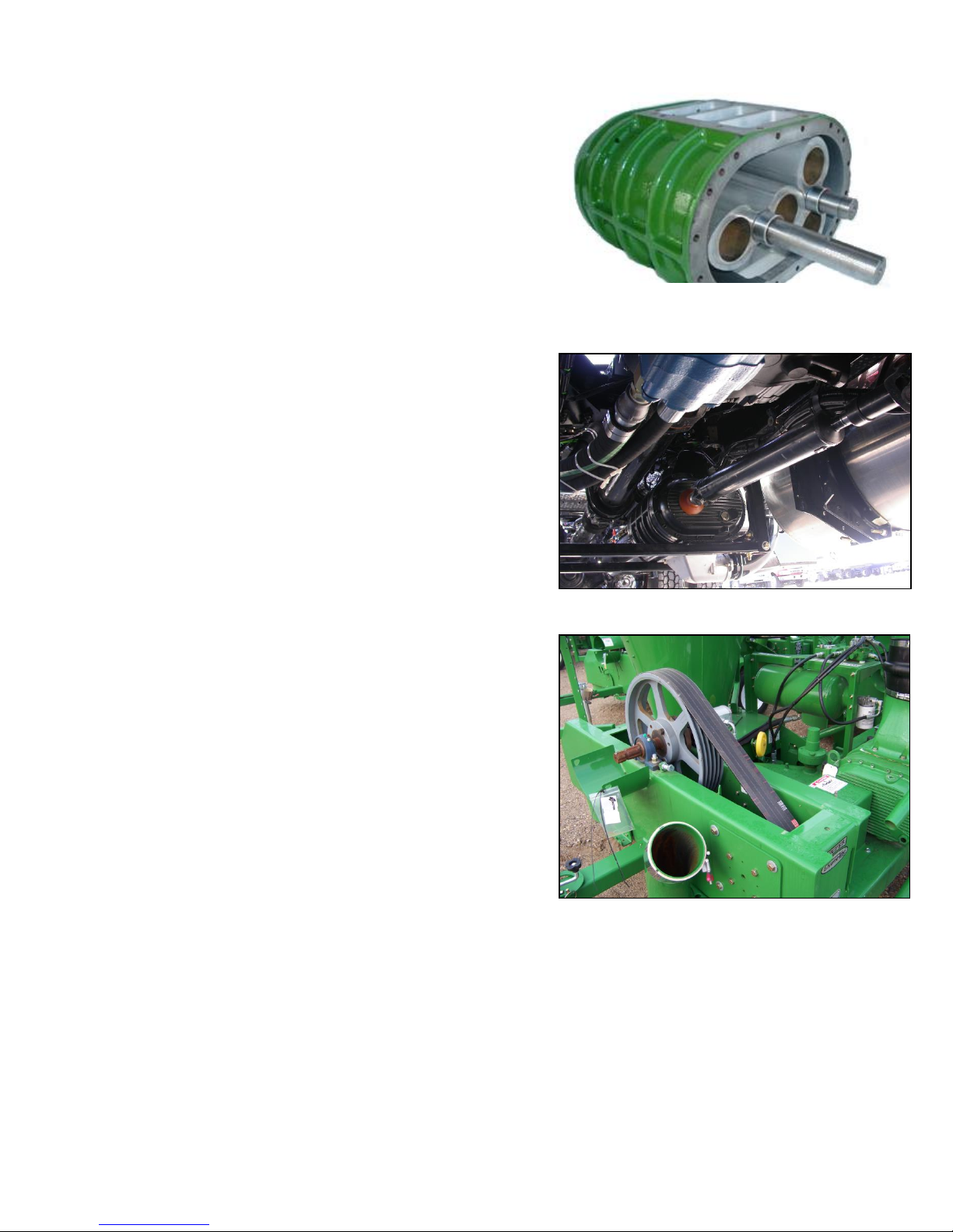
Refer to Figure 1. Rotary positive displacement design
incorporates the use of two figure eight impellers which
rotate in opposite directions to deliver a metered volume
of air. The impellers are separated by minute clearances
which are designed into the unit. These clearances are
maintained by timing gears.
CONSTRUCTION
Walinga blowers are ruggedly built for long life. Impellers
are dynamically balanced to operate without vibration.
Large alloy steel shafts are ground and polished.
Bearings are heavy duty anti-friction type which enable
the blower to maintain its original factory clearances.
Bearings are protected from dirt and contamination by oil
seals. Precision, steel, helical gears are oil lubricated by
a completely self-contained splash system which
atomizes the oil. Breathers are provided to prevent the
air from being contaminated by the blower lubricant.
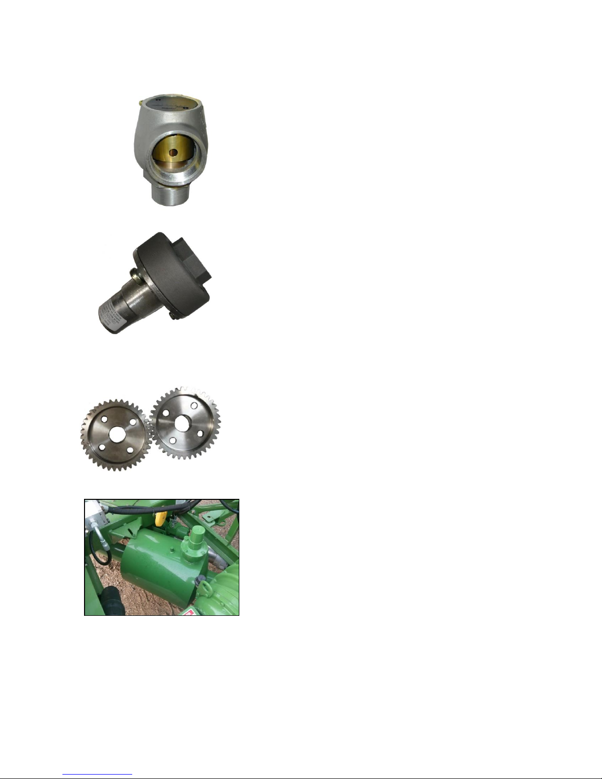
TYPES OF DRIVE
Direct: Locked bearings on both impeller shafts enable
the blowers to be direct connected. The entire line is
also available with flange adaptors and couplings for
direct connection to internal combustion engines as used
on WALINGA Trailers and Transfer Units. (See Figure
2). In addition, WALINGA blowers are available as
power take off (PTO) units with gear heads in a selection
of ratios to approximately 2.25:1.
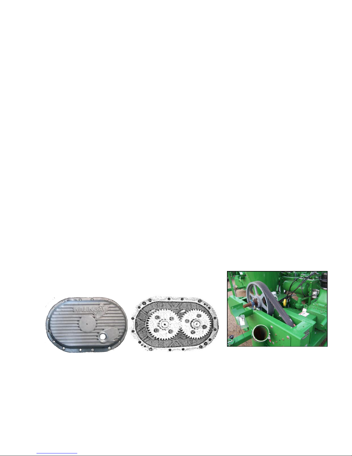
V-belt: Walinga blowers can be V-belt driven to permit
changes of speed to accommodate variations in
operation requirements. (See Figure 3)
Fig. 1
Fig. 3
Fig. 2

Blower Repair & Maintenance Manual #34-05198-6 v1.2 11.2014
8
SPECIAL FEATURES OF WALINGA BLOWERS - CONT’D
Fig. 4
RELIEF VALVES
VACUUM RELIEF VALVE, spring loaded type.
Built in 1-1/2”, 3”, 4”, and 6” sizes (Figure 4).
Fig. 5
PRESSURE RELIEF VALVE, spring loaded type (Figure 5).
Both valves are supplied as standard equipment.
Fig. 6
TIMING GEARS
Walinga units are fitted with precision steel helical gears and the
exclusive WALINGA TIMING HUB which enables the user to
easily retime the unit in the field and has great shock absorbing
qualities (Figure 6).
Fig. 7
MUFFLER
To minimize sound level with little pressure drop, space and
weight saving packaged-type mufflers are supplied
(Figure 7).

Blower Repair & Maintenance Manual #34-05198-6 v1.2 11.2014
9
SECTION ONE:
LUBRICATION
Anti-friction bearings and precision, steel helical gears are oil lubricated by a completely self-contained splash
system which atomizes the oil. No external oil feed systems or coolers are required.
Units are shipped with oil in the gear case or bearing housing. Do not operate before checking lubrication. The
vent and oil level plug arrangement are shown in figure 8. Remove the oil fill plug from the fill hole at the top of the
cover and the plug from the oil level hole located at the side of the headplate. Fill the housings until oil drips out of
the oil level hole. Do not overfill. * Replace both plugs. Use Walinga Super Duty Blower Oil (Walinga Part# 98-
13813-5) In most cases, operating temperature of the blower will be in the 100-250 Deg. F. range. Normally the
gear case should be drained, flushed, and refilled every 100 hours or annually. If inspection indicated it is
necessary, do at shorter intervals. The oil level should be checked daily.
Fig.8 Blower Schematics
* On units equipped with sight glass, check to be sure that oil levels registers a quarter of the sight glass.
Table 1
BLOWER MODEL #
FRONT
REAR
510
1.14 (1.20)
1.40 (1.50)
614
1.40 (1.50)
2.50 (2.60)
OIL CAPACITY LITERS (US QUARTS)
SPECIAL NOTE: As a result of blower operating temperatures, condensation can occur and result in water formation
in the lubricating oil reservoir. It is important that any water accumulation be eliminated, in order to ensure proper
lubrication and long life.
Allow blower to cool down before driving away to prevent condensation and freeze up in cold weather.

Blower Repair & Maintenance Manual #34-05198-6 v1.2 11.2014
10
SECTION TWO:
MAINTENANCE-RETIMING
RETIMING
Aside from lubrication covered in Section One, the only maintenance procedure which may arise and
needs explanation in the manual is the retiming of WALINGA blowers. Originally, the impellers are
separated by pre-determined minute clearances which are designed into the unit. These clearances are
maintained by the timing gears. Any malfunction which disrupts this clearance must be corrected and the
unit must be retimed.
Retiming is necessary to reset impeller clearance after a blower has been jammed and the removal of the
foreign material does not stop the knocking or pounding during operation.
GEAR CASE REMOVAL
The Gear case is secured to the headplate with socket head cap screws. (Figure 9) Drain oil from gear
case and remove bolts. Lift gear case away from headplate. Timing gears and gear end bearings are now
exposed. (Figure 10) On completion of maintenance work, be certain that gear case is resorted to original
position, with the oil-fill port up. Replace gasket or use a paste-type gasket compound on the mating
surfaces. Always relubricate before starting.
INLET AND OUTLET HOUSING REMOVAL
WALINGA blowers are equipped with housing for channelling air into the transmission lines. To expose
the impeller chamber, remove the bolts connecting the housing to the impeller cases and headplates, and
remove. Before housing is installed, after completing internal work, inspect housing gasket. Replace if
necessary
Fig. 11
Fig. 9 Fig. 10

Blower Repair & Maintenance Manual #34-05198-6 v1.2 11.2014
11
DETERMINING PROPER IMPELLER CLEARANCE
The timing of a blower is the setting of one impeller with respect to the other so they do not touch during
operation. The clearances between the impellers are measured at points o-o and c-c when the impellers
are in the positions shown in the Fig. 12 below. Note that the impellers are shown viewed from the drive
end of the blower; always face the drive shaft end when determining clearance.
Table 2
CLEARANCES FOR IMPELLERS INCHES
GUELPH
SERIES
TIMING
CLEARANCE
TIP CLEARANCE
END CLEARANCE -
SHAFT END
END CLEARANCE –
GEAR END
510
.009 MIN.
TOP: .008 MIN.
MID: .005 MIN.
BOT: .004 MIN.
.009 MIN.
.005 MIN.
614
.011 MIN.
TOP: .013 MIN.
MID: .008 MIN.
BOT: .005 MIN.
.012 MIN.
.005 MIN.
Denoted
Below
D
TOP: A
MID: B
BOT: C
F
G
Attention: The timing and tip clearances are very important. Maintaining proper clearances will prevent
damage to the impellers and will ensure maximum performance.
Fig. 12 Impeller Clearances

Blower Repair & Maintenance Manual #34-05198-6 v1.2 11.2014
12
DETERMINING PROPER IMPELLER CLEARANCE (con’t)
The following drawing illustrates how to check the minimum end clearances at the drive and gear end of
the blower. The hammer is used to ensure that the play that is inherent in the spherical bearings is to the
appropriate side and the clearance measurement is truly a minimum clearance measurement. Once
again this minimum spec should be taken at the tightest point. This means that when the shims and
cartridges are tightened into place and each impeller is hit down toward the drive end that (for a 614
blower) a .012 in feeler gauge should slide through with no more tension then the standard feeler
gauge test everywhere between the headplate and impellers.
Fig. 13 Checking Minimum End Clearances

Blower Repair & Maintenance Manual #34-05198-6 v1.2 11.2014
13
RESETTING IMPELLER CLEARANCES
Refer to Figure 14 below.
Impellers are held in time by gears which are bolted to a timing hub, which in turn is secured to the
serrated impeller shaft by a lock nut. The timing gears can be rotated in relation to the hub by loosening
the cap screws. Because the cap screw holes in the gear are oversized, the gear hub will rotate –within
limits –when the screws are loosened.
To retime, loosen the four cap screws (A) to locknut (B), and the lock washer (C) in one gear only. Wedge
the two impellers together against the exact amount of shim stock required to establish proper clearances
as calculated in the preceding sub-section: “Determining Proper Impeller Clearances.” Secure the gear in
new position with cap screws (but do not tighten) and rotate impellers by hand. Recheck clearances. If
proper timing has been re-established, tighten cap screws with a torque wrench (refer to accompanying
chart for correct values). Tighten lock washer and locknut.
Install gear case (See Gear Case Removal subsection) and re-lubricate.
Table 3
TORQUE VALUES
5” Gear
6” Gear
42 FT. LBS.
55 FT. LBS.
C
B
A
Fig. 14

Blower Repair & Maintenance Manual #34-05198-6 v1.2 11.2014
14
ASSEMBLY AND DISASSEMBLY OF BLOWER
Fig 15
DISASSEMBLY OF BLOWER
STEP
1
2
3
4
5
6
7
PROCEDURE
Drain oil from front and rear covers. (A)
Unbolt covers by removing all exposed socket head cap screws. (B)
Remove locknuts (C) lockwashers (D) from shaft on gear end of blower.
Remove bolts (E) and washers (F) from timing gears, match the timing gears and lift
them off of the hubs. (G)
To remove timing hubs and cartridges install two long 5/16” bolts in the threaded holes
in each cartridge. Pull cartridge and timing hubs off of the shafts by evenly turning down
The long 5/16” bolts.
Remove the oil slingers (H).
Follow step 5 for removal of front cartridges.

Blower Repair & Maintenance Manual #34-05198-6 v1.2 11.2014
15
Disassembly of Blower (con’t)
STEP
8
PROCEDURE
Remove retainer rings (I) from gear end bearing cartridges and remove bearings (P)
from cartridges
9
10
11
12
13
Remove seals (J) and O-rings (K) in cartridges.
Mark position of headplate (L) to housing (M).
Remove the two counter-sunk head capscrews and the two dowel pins from each
headplate.
Remove one headplate (L).
Mark the position of the long impeller (N) in the housing and slide impeller out of
housing.
Remove the other headplate (L)
Clean all parts and inspect all parts for wear or damage.
ASSEMBLY OF BLOWER
STEP
1
2
3
4
5
6
7
PROCEDURE
Set housing on work bench with the casting number (510G) on the right had side
and up.
Install the headplate on the end facing. If sameheadplate is used install 2 –5/16”
dowel pins and two –3/8” X 1” socket cap screws in counter sunk holes, also 4 –
3/8” X 1 – ¾” sockethead capscrews evenly spaced. (Do not tighten completely)
(Make sure the ventholes in headplate are pointing down.)
Turn the casing around and return the impellers in housing as marked (Re: step 12
of Disassembly)
Install the other headplate doing the same as (Step 3).
Check bearings for wear and damage. Replace where required.
Install new seals and O-rings in cartridges. Return bearings to cartridges. Make sure
the bearings stick slightly out of the cartridge, approximately 1/8”. Reinstall retainer
rings using new 10 –24 X 1/2” nylock socket head capscrews, on gearend cartridges
only.
Lubricate cartridge pockets in the headplates and the shaft sleeves where the seals
and O-rings fit with oil.

Blower Repair & Maintenance Manual #34-05198-6 v1.2 11.2014
16
ASSEMBLY OF BLOWER (con’t)
STEP
8
9
10
11
12
13
14
15
16
17
18
PROCEDURE
Drive cartridge onto shafts with a driver, make sure the cartridges with the retainer
rings are on the splined end of the shafts.
At this time only the cartridges on the front of (drive end) the blower are to be bolted
down using 5/16” X 1” nylock socket head capscrews.
Cut two pieces of pipe* 1-1/2” long 1-3/8” O.D. to fit over splined end of shaft and
long enough to allow end lock nut to be put on. Tighten locknuts to hold bearing tight
on shaft.
*(Used for assembly purpose only.)
Install two long bolts in threaded holes in rear cartridges. (Do not tighten) Make sure
threaded holes run from left bottom to right top when blower is lying flat. This is to
allow shims to clear bolts.
Check clearance between the impeller and the housing by sliding a feeler gauge
between impeller and housing, and rotate impeller in casing, doing so at all four
corners, top and bottom. Impellers have to be centered in housing with not less that
.007” clearance. If improper clearance cannot be achieved remove the dowel pins
and follow step 13 and 14.
If new headplates or new housing are used adjust the headplates by tabbing them
from side to side and up and down until centered in housing with not less than .077”
clearance.
Tighten the four capscrews in each headplate and check clearances again, if they
are satisfactory drill and ream new holes for the 5/16” dowel pins, these pins are
press fitted.
After impeller to housing clearances are set, tighten the two long bolts in the
cartridges lifting the cartridges away from the headplate.
Slide shim between cartridges, approximately 0.015” less that clearance between
flange of the cartridge and headplate. Make sure the same thickness of shims are
used on each side of each cartridge. Loosen the long bolts in the cartridges and bolt
the cartridges to the headplate.
Check with a feeler gauge inside at the gear end between each impeller and
headplate, it must have 0.008” clearance. If the clearance is not 0.008” adjust by
adding or removing shims. When the gear end is adjusted, check clearance on drive
end of blower to be not less than 0.012”. If it is less than 0.012” a gasket has to be
installed between the headplate and the housing.
Once the clearances have been set between the impellers and endplates remove the
two long bolts from each cartridge and install new 5/16” X 1” nylock capscrews to
bolt cartridge to headplate.

Blower Repair & Maintenance Manual #34-05198-6 v1.2 11.2014
17
Assembly of Blower (con’t)
STEP
19
20
21
22
23
24
25
26
PROCEDURE
Remove the locknuts and the pipe used in step 9 from the shaft and put the
impellers in 45° position 88, top side of impeller touching bottom side of other
impeller. In this position slide a 0.010” -0.012” feeler gauge between the impellers.
Lay the timing hubs loose on the shafts so that the splines just start on the shaft
splines. Lay the timing gears on the hubs lining up the bolt holes on the gears with
those on the hubs. Draw a line across both gears and shaft ends. Mark gears and
shaft ends 1 –2 and take gears off, draw a line across hubs lining up with the line
on the shafts, mark hubs 1 –2 (same as the gears). Heat up the timing hubs and
drive on splined shafts (Make sure the lines previously marked line up).
Lay the timing gears on the hubs making sure that the lines line up, and bolt them on
with 3/8” X 1-1/4” socket head capscrews and timing washers. Hold the impellers
together with 0.010” feeler gauge in between while installing the bolts.
Rotate the impellers while holding a 0.010” – 0.012” feeling gauge between center of
impellers. The feeler gauge should slide through evenly while rotating impellers in
either direction. If there is a tight spot while rotating the impellers, loosen the timing
bolts until finger tight and tap on gear carefully using an aluminum bar and hammer
to shift the position of the gear on the hub.
After the timing has been set install lockwashers (new) and locknuts on gears.
Tighten the timing bolts until they sink into the washers. Install two oil slingers at
front of blower and O-ring on the long shaft above the oil slinger.
Recheck all clearances and if satisfactory reinstall front and rear covers using new
gaskets. Make sure input seal hole in the front cover is centered around the shaft.
Install new seal .
Fill blower with oil up to its proper level and follow start-up check list.

Blower Repair & Maintenance Manual #34-05198-6 v1.2 11.2014
18
SECTION THREE:
REPAIR AND REPLACEMENT
With proper maintenance and lubrication, normal life of bearings, gears and seals can be expected. To
maintain the efficiency of your unit, however, these parts must be repaired or replaced when required.
Fig. 16
TIMING GEAR AND HUB REMOVAL
1. Remove the gear case (Refer to Gear Case Removal subsection).
2. Remove the lock nuts (A) and lock washers (B) from both shafts. Match-mark the shafts, gears
and hubs to assure proper repositioning on completion of maintenance work. We recommend
gears be replaced in sets only.
3. If maintenance work does not require detachment of gears from the timing hubs, these
subassemblies should be withdrawn from their respective serrated shafts simultaneously. On
completion of maintenance work, the return of the gear-hub sub-assemblies to their matched-
marked positions will eliminate the need for retiming.
4. If gears must be detached from the timing hubs during repair work it is important that the unit be
retimed, To separate gears (C) from hubs (D), remove four cap screws (E) from each assembly.
5. To reassemble, snug up but do not tighten bolts which hold gears to hubs and restore to their
respective shafts. Replace –but do not tighten –the lockwashers and nuts to each shaft.
Establish a position for one shaft and tighten the bolts, lockwashers and nut on that shaft only.
Then proceed with retiming in accordance with instructions outlined in “Resetting Impeller
Clearances”. Tighten the lockwashers and nuts and use a torque wrench to tighten the cap
screws on the timing hub. Replace the gear case and follow “Blower Start-up Checklist”

Blower Repair & Maintenance Manual #34-05198-6 v1.2 11.2014
19
GEAR END BEARING AND SEAL REPLACEMENT
Fig. 17
1. Remove gear case (refer to Gear Case removal subsection). Check the fixed end impeller
clearance. This clearance must be duplicated when repairs are completed. Remove the lock nuts
and washers from the ends of both shafts and match mark the shafts, gears and hubs to assure
repositioning during reassembly… this is important. Remove gears and hubs simultaneously. In
some cases, a gear puller might be necessary in this operation.
2. Refer to figure 16. If shim spacers (A) were added during production, they will now be exposed
behind the bearing cartridge (B) on the gear end of the unit. The spacers have been installed to
assure accurate positioning of the impellers between the headplates; hence, it is important that they
be returned to their exact positions on reassembly. Accordingly, match mark the spacers at this point
and be prepared to detach them on removing the four socket head cap screws (C) which hold the
bearing cartridge in position. After this has been accomplished insert two long bolts (D) as indicated
and tighten against the headplate, applying equal turns to each bolt to assure an even withdrawal of
the cartridge. Detach the cartridge and remove the bearing retaining ring from the face of the
cartridge.
3. A seal is located behind each bearing fit. Whenever a cartridge is removed for repair purposes,
always install a new seal before reassembly. This can best be accomplished by using a driving
instrument having the same approximate O.D. as the seal; use normal precautions not to damage
the new seal during installation.
4. On completion of repair or replacement work, return the bearing cartridges to their respective shafts
and restore the shim spacers to their original positions, using the match marks as guides. Extreme
care must be taken to avoid damaging the sealing elements when they are moved over the shafts. It
is good practice to wrap a piece of light shim stock around the shaft to prevent cutting or damaging
of the seal on the serrated surface.
5. Return bearings and secure in position with the retaining rings. Hub and gear sub-assemblies must
be replaced simultaneously according to match marks made during disassembly. Check the fixed
end clearance. If necessary, add or delete shims behind the bearing cartridge flange as needed to
restore original fixed end clearance.
A
B
C
D

Blower Repair & Maintenance Manual #34-05198-6 v1.2 11.2014
20
BEARING AND GEAR REPLACEMENT ON GEAR HEAD UNITS
Fig. 18
When excessive wear has spent the effectiveness of any one of the three bearings and/or two gears in
gear head units, it is recommended that all five components be replaced to assure optimum
performance and trouble-free service. Installation of a new oil seal is recommended each time the unit
is disassembled.
DISASSEMBLY
STEP PROCEDURE
1. Unbolt the gear box cover (A) and the adapter (B) from the impeller case by removing all
exposed socket head cap screws (C). Detach the cover from the adapter. Note: At this
point on some units, four socket head cap screws may be seen on the exposed end of
the headplate (D). Do not remove these screws.
2. Remove the button head cap screw (E) and the retainer plate (F) from the impeller shaft
(G).
3. Attach a standard gear puller to the pinion gear and remove both the gear and the
bearing from the impeller shaft in one operation.
4. Withdraw the retaining ring which secures the outer race of pinion bearing (H) in the gear
box cover. Use a gear puller or similar tool remove the outer race.
5. Remove the input shaft assembly (J) from the gear box adapter.
6. Use a press with a support on the gear surface to drive the input shaft out of the gear and
bearing. Reverse the shaft assembly and repeat this procedure to press the shaft out of
the other bearing.
7. Remove the oil seal by drifting it out of the gear box cover.
This manual suits for next models
1
Table of contents