Wallace Pumps UNI-SAN User guide

27-05-19 UNI-SAN Domestic Instructions Page 1
UNI-SAN DOMESTIC
Automatic waste water only collection tank and electrically operated pump
system.
INSTALLATION AND SERVICING INSTRUCTION MANUAL
PLEASE READ ALL INSTRUCTIONS PRIOR TO PROCEEDING WITH ANY WORK
A permit may be required. Check with the plumbing and drainage and the electrical inspectors before installation.
Local regulations may stipulate additional installation requirements.
AFTER INSTALLATION, THE INSTALLER MUST HAND THIS MANUAL TO THE OWNER FOR THE PROPER
OPERATION AND MAINTENANCE OF THE UNIT. Failure to do so will result in the installer being liable under
current legislation for future claims resulting from incorrect operation or servicing.
Figure 1 : Dimensions Figure 2 : Cut-away view through the cover showing the dry mounted
pump and motor unit, mounted on a sealed gas and water-tight tank.
PAGE INDEX
Section
1. General view and connections................. 2
2. Product overview............................... 3
3. Applications....................................... 3
4. Features & benefits............................ 4
5. Overall building design and
Pump hydraulic capability... 4
6. Warning : for your safety.................... 5
7. List of fittings supplied,
recommended extras and tools......... 6
Section
8. General installation aspects
and electrical data..................... 6
9. Specific installation procedures.......... 7
Shower tray or bath plug height.......... 8
10. Care and servicing............................. 9
11. Warranty and Limitations....................10
Appendix A: Rotating the delivery direction...11
Appendix B : Fault finding chart......................11
Appendix C : Remote installations..................14
Limitations : We reserve the right to change these instructions and improve the product without prior notice.
AUCKLAND PALMERSTON NORTH CHRISTCHURCH
55 MAURICE RD, PENROSE 35 BUCHAN ST
POBOX12387 SYDENHAM
PH 09 622 9100 PH/FAX 06 323 4445 PH 03 365 6453
FAX 09 622 9119 FAX 03 366 6995
A division of CONSOLIDATED ALLOYS (NZ) Limited.
1. GENERAL VIEW & CONNECTIONS
UNI-SAN
Pump cover
O-ring sealed lid
Gas and
watertight
collection unit
Dry mounted pump and motor
unit
Vent and inlets
can be fitted
wherever
required on
tan
k
Gas and watertight
collection tank

27-05-19 UNI-SAN Domestic Instructions Page 2
Figure 3 : Connections and names of parts
1. Cover for pump, motor and controls. Lift to remove.
2. Inspection lid - Screw in type with o-ring seal; turn anti-clockwise to remove. The unit must be installed upright
with the inspection lid on top.
3. Collection tank - Fittings supplied are shipped inside. Cut holes neatly and carefully. Do not subject to impacts,
scratches, scouring or partial drilling that may weaken it. Take care not to damage internal parts with hole saws.
If the unit is not installed in the same room as the fixtures, it should be plumbedaccording to Appendix C. Access
must be provided for maintenance at all times.
4. Pump delivery 25 mm BSPF -3 optional directions. Use Class B or D or Class 4.5 PVC pressure pipe. Install a
union/coupling close to the pump for future pump removal without disturbing the pipework. Securely strap and
isolate the pipe from the building structure to prevent vibration or noise transmission during operation. Any
horizontal section of the delivery pipework should always have a continuous rise towards the soil or waste pipe
connection. It should never be level or have a fall.
5. Tank vent connection - 32 mm valve socket is supplied inside the tank. Use 32 mm pipe to run the vent to a
termination point in accordance with the Building and Plumbing Code. Do not use an air admittance valve,
e.g. a "Hunter Valve".
6. Inlet connections using PVC valve sockets with back-nuts and washers can be installed anywhere on the four
walls, or the top of the collection tank (except over the float switch) for fixtures or appliances which have an
overflow level higher than the unit. Allowroom for the back-nut when cutting the hole. Check that either the inflow
liquid or the protruding pipe inside the tank will not damage fittings inside the tank or hinder the operation of the
float level switch. One 40 mm valve socket is supplied with the unit.
7. UNI-SAN Bottom Inlet Valve, unless the unit is installed below the floor level, should be used for a shower or
a bath connection, not shared with any other connecting fixtures or appliances. If both are connected, each must
have its own UNI-SAN Bottom Inlet Valve. It can be made with a hole-saw on any of the four walls, 80mm centre
height from the base. The inlet pipe must be braced to prevent the water pressure from dislocating the push-fit
connection. The valve is purchased separately.
8. All fixtures and appliances connecting into the UNI-SAN must discharge through a trap and a waste strainer
with a maximum of 10mm diameter apertures. All pumped appliances, such as washing machines and
dishwashers, must discharge via an approved waste system which includes an air gap and a trap.
9. The 25 mm swing check valve supplied must be installed in the delivery pipe in a vertical position within one
metre (pipe length) of the unit to stop backflow of liquid from the pipe back into the collection tank. The 25 mm
union shouldbe installed between the pump and this valve.
10. Isolation Valve – A 25 mm full flow ball valve for installation after the 25 mm swing check valve is supplied
11. Labels warning against inappropriate discharges are supplied and should be affixed on the appropriate fixtures
and appliances connected.
2. PRODUCT OVERVIEW
9. 25 mm swing
check valve

27-05-19 UNI-SAN Domestic Instructions Page 3
The UNI-SAN pump is designed for the disposal of waste water and any solids which can pass through a plumbing
trap and a waste strainer with a maximum of 10 mm diameter apertures. The unit is capable of pumping the effluent
from a kitchen waste unit, but it is neither a waste disposal macerator nor suitable for pumping raw sewage waste
from a toilet. For these other applications, contact Wallace Pumps or a Distributor for other options.
The WALLACE UNI-SAN collects the gravity fed waste liquid into its collection tank. When a set water level is
reached, the level switch inside the collection tank automatically activates the powerful quiet pump to deliver the
effluent under pressure to the desired location through a 25 mm internal diameter pipe. The discharge point will
usually be into a gulley trap or into a soil stack.
Due to the small pipe size and pump pressure, the delivery can be run virtually anywhere, in any direction,
- through walls,
- through ceiling spaces,
- under floors,
- around, under and over obstacles.
The unit enables the installation of a variety of equipment where this was previously impossible due to economic
constraints, physical limitations, or because there was no unit available with adequate performance or reliability.
The UNI-SAN has been developed to overcome these problems, including
- below sewer-line installations,
- where gravity fall is not possible,
- physical restrictions, e.g. concrete walls or concrete floors,
- where new pipes cannot be run under the floor, such as concrete floors,
- where large diameter 80 - 100 mm gravity lines are not appropriate for the location,
- and many other situations.
3. APPLICATIONS
The UNI-SAN range is made up of two models, and as the names suggest there is one for domestic applications
and one for commercial. Both units are the same dimensions and pumping performance, the major differences are
in the materials of construction, level control and motor switching design.
The UNI-SAN DOMESTIC is NOT to be used in commercial applications.
The UNI-SAN collects and automatically pumps away waste water from the following and many other sources :
- laundry tubs,
- domestic and commercial sinks with or without waste disposal units,
- domestic and commercial clothes washing machines,
- domestic and commercial dishwashing machines,
- bar facilities,
- bath, shower, vanity,
- air conditioning condensate,
- dehumidifier water,
- a floor waste gully trap plumbed according to AS3500 and Appendix C, Figure 7c.
PROVIDED THAT
- in a multi-storey construction, they are all located on the same floor level as the UNI-SAN,
- maximum temperatures in the collection tank are 60C continuous and 95C intermittent,
- no acids, solvents, paints, petroleum products, corrosive/abrasive liquids or excessive fats are discharged
into the unit
- and the volume of water discharged into the unit from fixtures and/or appliances operating at the same
time must not exceed pump output.
Contact our office for advice :
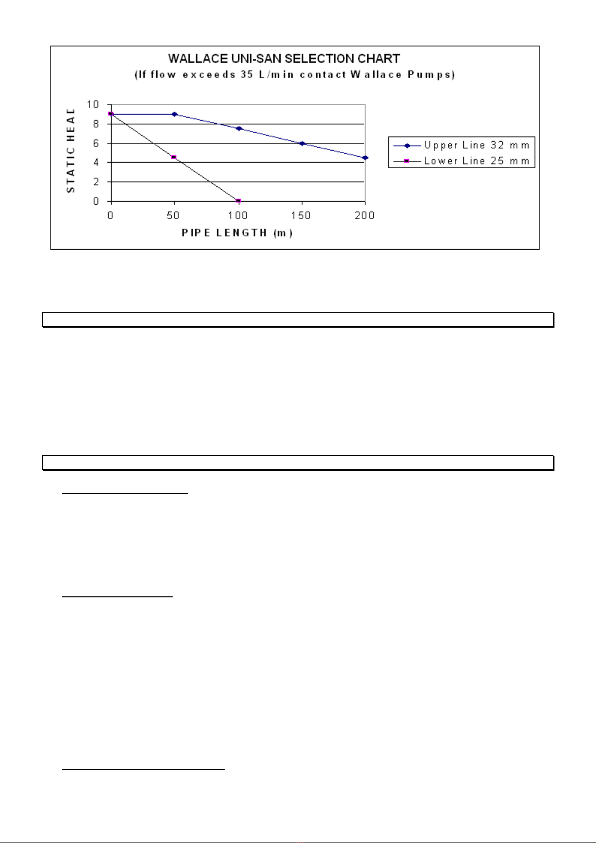
- for inflows higher than 35 litres per minute,
- for general commercial applications,
- where there is a high quantity of fats being discharged,
- for printing, photographic or similar trade processing waste.
Typical applications for the UNI-SAN DOMESTIC are :
- basement facilities
- relocated domestic amenities where gravity fall to existing sewer connections is not possible
- master bedroom en-suites without toilet ( Refer MULTI-SAN unit for toilet applications )
- executive bars and showers
- re-developed apartment blocks in inner cities enabling waste pipes in ceilings
Typical applications for the UNI-SAN COMMERCIAL are :
- arcade or retail developments including hair salons, cafeterias, delicatessens, etc.
- amenities in factories built on concrete floor slabs

27-05-19 UNI-SAN Domestic Instructions Page 4
- photography development room.
- bakeries and cafes
You must consult your local plumbing and drainage inspector for a permit / consent approval.
4. FEATURES AND BENEFITS
FEATURES BENEFITS
Higher pump head
( longer run & higher vertical height )
Pumps higher and further
Higher flow rate Empties faster and accepts multiple discharges
Dry mounted motor and pumping unit Easier to clean and service and more reliable
Heavy duty motor Longer lasting
Heat and overload protected motor Reduces risk of costly burnt-out motor
One piece collection tank No joints to leak liquid or odours
Multiple entry options into the tank Can service many utilities from many directions
3 alternative directions for the delivery pipe Flexible pipe-out
Higher water temperatures than other systems Far wider range of applications
Vortex impeller design Passes hair, lint, fibre, tea bags, etc without blocking
5. OVERALL BUILDING DESIGN AND PUMP HYDRAULIC CAPABILITY
To ensure that the UNI-SAN is suitable, check your installation requirements against the dimensions and hydraulic
capabilities of the unit.
-Ascertain that the combined inflows into the unit at any time do not exceed 35 litres /min
-Measure the overall height of the delivery pipework ( from the bottom of the tank to the highest point in the delivery
line, also referred to as Static Head ).
-Measure the total run of all vertical and horizontal pipes from the pump to the sewer drain.
-Count the number of bends in the pipeline. Each is equivalent to 1 metre run.
Figure 4 : Example of hydraulic selection ( equal to position A on Figure 5 )
Plot the intersection of metres overall height and metres total run on the chart below (Figure 5).
SELECTION EXAMPLES
Example 1 Static head = 3m.
Horizontal Pipe ( 21m) plus 6 x 90 bends ( 6m equivalent) = 27m total run of pipes.
Plot on the chart, the intersection is below the lower line. Use 25 mm or 32 mm pipe.
Example 2 Static head = 6m.
Horizontal Run ( 61m ) plus 9 x 90 bends ( 9m equivalent ) = 70m total run of pipes.
Plot on the chart, the intersection is above the lower line and below the upper line. Use 32 mm
pipe.
Example 3 Static head = 6m.
Horizontal Run (180 m) plus 9 x 90 bends ( 9m equivalent) = 189 m total run of pipes.
Plot on the chart, the intersection is above the upper line. Contact Wallace Pumps to discuss
alternatives.
Figure 5 : Hydraulic selection

27-05-19 UNI-SAN Domestic Instructions Page 5
NB: The above chart and figures are based on using Class B or D or 4.5 PVC pressure pipes and one 32 mm
swing check valve. This will ensure a minimum delivery flow of 35 litres per minute from the WALLACE UNI-SAN.
This is in excess of the highest output domestic washing machine that is currently known to be available. If you are
uncertain, call your appliance supplier for the output flow for your particular unit.
6. WARNING : FOR YOUR SAFETY
The UNI-SAN unit requires a power supply rating of 230 Volts 50 Hz single phase.
This apparatus must be earthed. To ensure safe operation, check that the three pin power point is earthed and
protected by a fuse or ELCB protection of an appropriate rating.
Also check with your local power supply authority. Their requirements may be additional to and over-ride those
listed above and in section 8.3.
When opening the cover or inspection lid, always switch the power off and ensure no liquid flows into the tank.
To prevent shock or fire hazard, do not expose this unit to rain, any type of moisture, flooding or overflows.
The wires in the main connection plug are coloured in accordance with the following code :
Earth : Green/Yellow Neutral : Blue Phase : Brown
7. LIST OF FITTINGS SUPPLIED AND RECOMMENDED EXTRAS
7.1 Unpacking And Inspection
Your UNI-SAN package should contain the following items
1 x WALLACE UNI-SAN pump unit
1 x 40 mm PVC valve socket, back-nut and washer for a 40 mm inflow waste pipe
1 x 32 mm PVC valve socket, back-nut with washer for the tank vent pipe
1 x 25 mm PVC swing check valve
1 x 25 mm PVC isolating ball valve
1 x 25 mm PVC union
7.2 Options And Supplies :
Additional materials you may require from your plumber/installer or local plumbing or building merchant :
40 mm UNI-SAN Bottom Inlet Valve for connecting a shower tray or a bath
PVC valve sockets with back-nuts and washers to suit the appropriate pipework
32mm - 50 mm PVC drain waste pipe(s) into the UNI-SAN
32 mm PVC waste pipe and cowl for the vent from the collection tank
25 mm (refer Figure 5) Class B or D or 4.5 PVC pressure pipe for the delivery pipe
any other size pipes as required
PVC fittings and cement as required (bends, sockets, traps and waste strainers, etc. )
PVC pipe "lubricant" (do not use petroleum based products)
Thread tape - do not use hemp.
Silicone sealant.
7.3 Tools Required for the installation
Stanley knife, or jig saw or hacksaw (for cutting out delivery pipe slot in the cover )
Half round file

27-05-19 UNI-SAN Domestic Instructions Page 6
Emery paper strip
50 mm O.D. hole saw (for cutting out UNI-SAN Bottom Inlet Valve hole)
42 mm O.D. hole saw (for cutting out tank vent pipe hole)
Other sizes as required, holes cut must be no more than 3 mm larger than the OD of the valve socket thread.
8. GENERAL INSTALLATION ASPECTS AND ELECTRICAL DATA
8.1 General
1. Where a permit or consent is required,it is recommended that the unit should be installed by a registered plumber
and the power supply should be connected by a registered electrician. It is the responsibility of the installer to
obtain the necessary permits and ensure full compliance with all applicable local regulations. The owner or owner's
agent must ensure that the UNI-SAN is compatible with the existing or proposed plumbing system design.
2. The installation of the unit and the swing check valve must comply with the following conditions
- they are easily accessible for servicing;
- service fixtures and appliances located on the same floor level as the unit, each must have awaste trap installed;
for below-floor installations refer to Appendix C.
- are in a clean, dry, non-floodable position, protected from UV and on a permanently sturdy support;
- design against overflow, flooding, unwarranted interferences or excessive moisture;
- protect from freezing of liquids in the unit and the pipework;
- the tank is installed with the screwed inspection lid on top;
- unless the unit is installed below the floor level as in Appendix C, Figure 7c, install an individual UNI-SAN Bottom
Inlet Valve for the shower tray and one for the bath;
- if installed outside or below the floor, the unit is installed according to Appendix C.
- all the requirements in these instructions are met.
3. Cut holes carefully. Check via the inspection lid, the position of fittings inside the tank before drilling. For PVC
valve sockets, allow room for the back-nut. Take care not to score or mark the tank as this may weaken it.
4. Modifications not described in this manual and without written authorisation by a Wallace representative will nullify
the Wallace Pumps warranty and durability compliance.
8.2 Plumbing
1.The connection to the soil and waste drain system must be carried out in accordance with the Building and
Plumbing Code. The connection of the unit's delivery pipe to a soil or waste pipe should be kept at least 0.5 metre
distance from any other connection. Also it must not be connected in a section of the pipe which runs the risk of
being flooded creating a back pressure down the pipework to the unit. The connection point is usually 600 mm
above the lowest W.C. connection or the lowest gully trap. Delivery into a gully trap must have an elbow to direct
the flow downwards. The connection of the delivery from the unit to a soil or waste pipe should be a swept
inspection bend in the direction of flow of the soil or waste pipe.
2. Any horizontal section of the delivery pipework should always have a continuous rise towards the soil or waste
pipe connection. It should never be level or have a fall. The pipework must be securely strapped and isolated from
the building structure to prevent vibration and noise transmission.
3. Install only the supplied swing check valve within one metre of the pump in a vertical position.
WARNING : Use of non-approved non-return valve will invalidate the WALLACE UNI-SAN warranty. The valve
must be installed in an easily accessible position for future servicing.
4. All pumped appliances, such as washing machines and dishwashers, must discharge via an approved waste
system which includes an air gap and a trap. BEWARE OF OVER TEMPERATURE DISHCARGE FORM
WASHING MACHINES.
5. Ensure that the 32 mm tank vent is installed in the top of the unit and that it extends full-bore to the external air
(the minimum height must be 50mm above the overflow level of the highest fixture discharging into the WALLACE
UNI-SAN) or terminated elsewhere as described in the current Building & Plumbing regulations. DO NOT use air
admittance venting devices as they do not let air out of the tank, eg: a "Hunter Valve".
6. It is important from a health and safety reason and for the protection of property, that an overflow relief pipe is
plumbed and delivered to a safe and visible area in the event that the discharge flows into the UNI-SAN exceed
the pump hydraulic performance capability or caused by a mechanical failure or a pipe blockage. Pumped
appliances and water supply can be safeguarded as per Section 10.4 (Overflow).

27-05-19 UNI-SAN Domestic Instructions Page 7
7. Install plumbing waste traps and strainers with a maximum of 10 mm diameter apertures in the inlet pipes to
prevent excessively large solids passing through.
8.3 Electrical Connection
1. The WALLACE UNI-SAN is fitted with a high quality 2900 rpm 2 pole speed motor :
Current : 2.45 amps FLC
Motor output : 0.4 kW
Cable: 1.5 metres of 3 core - supplied with the unit
Connection Plug : Standard 3 pin domestic earthed - supplied with the unit
Supply : Single phase 230 volts 50 Hz.
2. Overload protection (thermal / overload) : the unit has a built-in automatically resetting motor overload. In the
event of a fault and trip, the pump may restart without warning. If the pump continually cycles on and off, switch
the power off and refer to the fault-finding section (Appendix B ).
3. Wiring connection : the electrical wiring connection type should preferably be the "Clipsal Permanent Connection
Unit with Neon" type, or PDL 253N, or similar. The permanent connection should be fixed in a position where it
cannot be reached by a person in a bath or shower or standing on a wet surface.
4. The unit requires a domestic 3 pin earthed single phase power supply. The appliance must not be connected
to a conventional plug, socket or adaptorwhen installed in a bathroom, unless properly protected by an approved
earth leakage circuit breaker or similar.
5. Refer Section 6 ( Warning : for your safety ) for additional electrical information.
Always refer to your local power supply authority for details of acceptable wiring, as their requirements over-ride the
guidelines above.
9. SPECIFIC INSTALLATION PROCEDURES
9.1 Pipework Sizes ( Pipe sizes are nominal internal diameters )
DRAIN from shower and bath to the UNI-SAN Bottom Inlet Valve(s) 32 - 50mm Waste Pipe
DRAIN from vanity, laundry, etc to the valve socket(s) 40 - 50mm Waste Pipe
DRAIN from kitchen sink to the valve socket 40 - 50mm Waste Pipe
DRAIN from Floor Waste Gully Trap plumbed as per Appendix C, Figure 7c,
to the valve socket 50-100mm Waste Pipe
VENT from WALLACE UNI-SAN to approved termination 32 mm Waste Pipe
PUMP DELIVERY from UNI-SAN to approved termination 25 mm PVC
ClassB/D/4.5PressurePipe
Note : Choice of pipework sizes vary with state and local plumbing regulations.
9.2 Layout And Pipe-Out Options The waste inlet valve sockets and Bottom Inlet Valve(s) can be installed in
any of the four walls, or in the top of the collection tank.
No inlet fittings or inflows should be in line with the operating range, or on top of the float switch.
The vent pipe must be installed in the top of the tank, anywhere around the inspection lid.
The pump is supplied with the delivery outlet out the end of the unit. If necessary and on request Wallace Pumps
can supply prior to despatch of the pump from our store with the outlet set to deliver out either side.
9.3 Positioning And Marking Out Decide which way round to install the UNI-SAN unit.
Place the unit in position. At this stage, you must visualise where the pipes will run from fixtures to the unit, where
the tank vent pipe and delivery pipe will run from the unit. Ensure that the whole system will integrate correctly in
terms of gravity fall requirements before proceeding.
If the UNI-SAN Bottom Inlet Valve is used, mark the centreline position(s) at 80 mm height above the base of the
unit, and no closer than 45 mm centreline from the side of the unit. If a valve socket is used, allow room for the
back-nut inside the tank to be at least 40 mm away from the fittings inside the tank and the corners of the tank and
check that the pipe protrusion is clear of the vent tube, the float level switch and its movement operation. View
through the inspection lid before cutting the hole.
Decide on the position of the vent pipe in the top of the tank. Mark the centreline for a 42 mm O.D hole to take the
32 mm valve socket, allowing room for the fitment of the washer and back-nut inside the tank.

27-05-19 UNI-SAN Domestic Instructions Page 8
9.4 Cutting Out Cut holes using the correct hole saw sizes. The holes cut must be no more than 3 mm larger than
the OD of the socket thread being fitted. Ensure the drill or saw does not penetrate excessively such that it would
damage the fittings inside the tank, especially the float level switch or its cable.
9.5 Fitting :
Tank vent connection: Push the threaded end of the 32 mm valve socket through the hole in the top of the tank.
Then via the inspection lid, firstly fit the washer and then the nut to the thread. Tighten the nut and socket firmly. If
necessary a small bead of silicone sealant can be applied to the tank side of the washer and thread inside the tank.
Tank inlet connection : Installation is the same as for the above tank vent pipe valve socket.
Bottom Inlet Valve : Note there is a triangular impression on the outside of the valve. This must be on top once
installed. Push the valve into the 80 mm centre height hole until its shoulder is hard up against the tank. Insert a
finger in the valve and ensure it operates freely. The flap should lift and fall back freely onto its seat. Do NOT use
sealant when installing the valve as it can interfere with the valve's operation.
9.6 Pipe-Out Sequence Fit the UNI-SAN unit in the desired position. Fit-out the pipework first, then fit the cover.
9.7 Tank vent Pipe Cement the pipe to the valve socket. This pipe should be run full-bore to the external air at an
approved termination point. Do not use air admittance devices (e.g. "Hunter Valves" ).
9.8 Pump Delivery Pipe The pump outlet connection is 25 mm BSPF. Refer to Section 5 "Hydraulic capability" to
determine the correct pipe size from this connection. Slip the delivery pipe in the ends of the swing check valve
supplied. Check the direction of flow and hand tighten the nuts on each end. It is possible to carfully tighten these
¾ to 1 more turn with a wrench. Install the isolating ball valve.
9.9 Waste Pipes to the WALLACE UNI-SAN
Run the pipes between your sanitary fittings and the UNI-SAN tank inlet and bottom inlet valve connections. Ensure
that the minimum fall is maintained and that the installation complies with the Building and Plumbing Code including
air breaks, strainers, traps, pipework sizes and lengths.
Pipework into the UNI-SAN Bottom Inlet Valve : The 40 mm PVC pipe connected must be chamfered on the outside
diameter and lubricated with PVC pipe "lubricant". Insert the pipe, 25 mm deep into the valve up to its internal
shoulder.
All inlets must have a waste trap connected. Vent the pipes where necessary.
9.10 Shower Tray or Bath Waste Height If the unit is not installed below the floor level, the minimum height of
the shower tray waste discharge point is 240 mm above the UNI-SAN base level. The final height is determined by
starting from the UNI-SAN Bottom Inlet Valve's 80 mm centreline and work back to the shower tray discharge point
at the minimum pipe fall rate. Add the necessary height for the trap to give you the total height from the floor to the
shower tray.
A shower waste pipe discharging into the unit must have its own un-shared UNI-SAN Bottom Inlet Valve. Similarly
a bath waste must have its own UNI-SAN Bottom Inlet Valve. If the unit is installed below the floor level as in
Appendix C, Figure 7c, a valve socket connection should be used instead of the UNI-SAN Bottom Inlet Valve.
9.11 High temperature installations

27-05-19 UNI-SAN Domestic Instructions Page 9
If not practical talk to Wallace Pumps about cold water solenoid valve injection systems for dishwasher
discharge.
9.12 Fitting The Cover Mark the pump delivery pipe centreline position on the cover and cut out with a hole saw
to suit the position of the selected 25 mm or 32 mm delivery pipe position. Cut down from the edge of the hole to
the base to create the slot necessary for installing and future removal of the cover. The pump cable power can be
run through this slot.
9.13 Connection To The Power Supply Connect the unit to the power supply. Ensure that this complies with all
the relevant requirements of the local power supply authority and any governing body. Switch on the power when
ready.
9.14 Testing Run water into the unit. The motor and evacuation should start when the liquid is approximately 200
mm deep in the tank and should stop at approximately at 60 mm depth. If the operation does not appear to be
correct, refer to the fault finding section ( Appendix B ).
10. CARE AND SERVICING OF YOUR UNIT
10.1 Normal Usage The UNI-SAN pumping system is designed for the disposal of waste water with solids which
are able to pass through a plumbing trap and a waste strainer with 10 mm diameter apertures. When fault-finding,
always switch the power off and take care to stay away from moving parts or electrical circuits when switching the
power on or when moving the float level switch.
Do not discharge acids, solvents, paints, thinners, petroleum products, corrosive/abrasive liquids, excessive fats or
any other products that may be harmful to the unit into the tank. A grease trap should be installed in commercial
applications and should be cleaned regularly. The unit is not designed as a kitchen waste disposal unit or for the
disposal of sewage. Refer to our office for the UNI-SAN model or other options.
10.2 External cleaning The external surface should be cleaned with a damp cloth, and dishwashing detergent if
required. Do not use abrasive liquids or pads, solvents or petroleum products as these may scour or damage the
surface.
10.3 CLEANING INSIDE THE TANK If you connect to a sink in a food preparation area you may experience fat
or sludge build-up problems in the tank, we recommend that you regularly clean (3 or 6 monthly) the unit with a
solution of household detergent or household bleach. Switch off the power supply. Mix a solution normally used for
vinyl floor cleaning. Pour into the tank through the inspection lid and leave to stand for 20 minutes. Switch on again
and flush with clean water. If required, the inside of the tank can be cleaned manually via the inspection lid.
10.4 Overflow Where a discharge flows into the UNI-SAN, adequate precautions must be taken to ensure that no
undesirable overflow can occur in the event of the unit not operating due to any cause. Likewise, you should not
continue to discharge more liquid into the unit if the pump does not start as the collection tank fills up or discharge
into it flow rates in excess of the capability of the pump. If you require higher flow rate capacity, call our office for
other options.
Three alternative protection systems can be installed :
1. An audible alarm can be fitted that is activated when the level of fluid inside the pump reaches a high level. This
alarm can also be wired to notify a Building Management System.
2. In addition, drainage into the UNI-SAN unit can be isolated by means of a fail closed solenoid valve on the water
supply to any fitting that discharges into the unit. This valve, if activated either by a power failure or a separate high

27-05-19 UNI-SAN Domestic Instructions Page 10
level switch in the UNI-SAN as described in the previous paragraph, would turn off the localised water supply to
fixtures and appliances discharging into the unit.
3. If appropriate, a suitable size overflow pipe for emergencies can be plumbed from the UNI-SAN to a suitable
delivery point.
10.5 Protect the unit from flooding or excessive moisture The UNI-SAN is an electrical appliance and therefore
is subject to damage if the electrical components are exposed to water or excessive moisture. Always secure the
cover lid in place and ensure any overflow / accidental leakage can drain away from the unit.
To ensure safe operation, ensure that the power supply is earthed and protected by a fuse or ELCB protection of
an appropriate rating.
10.6 Protect from frost If the installation is exposed to frost conditions, adequate precautions must be taken to
prevent against freezing of liquids inside the UNI-SAN and all the pipework into and out of the unit. Icing may result
in permanent damage to the unit. Never pour hot water over the unit and do not use anti-freeze agents.
10.7 Regular Servicing The UNI-SAN must be serviced at regular intervals by a qualified technician. The
maximum interval between services should be 12 months; more frequently if the usage is high, such as in
commercial installations. The interior of the collection tank should be kept clean. The intervals between
cleaning will be determined by the type of usage. Regular inspection will determine the required frequency.
Inspection and access is via the screw-on lid on top of the tank. Record any part that us changed / replaced
and why. Record any problems that occur.
Ensure isolation and disconnection of the power supply to the pump before and whilst carrying out any
servicing work on the unit. Also ensure no liquid will flow into it during servicing.
10.8 Modifications or Repairs Wallace Pumps does not warrant for any damage to the unit or any other property
caused by any un-authorised modifications/repairs in contravention with the Company's instructions or by use of
materials or fittings not supplied by Wallace Pumps. Where a claim arises, we suggest you contact the installer for
rectification.
11. WARRANTY AND LIMITATIONS
The purchaser and / or installer must ensure full compliance with all applicable regulations.
WallacePumpsdoesnot warrant for any damage to the unit or any other property caused by poor quality installation,
workmanship or installations in contravention with the Company's instructions, or by failure of materials or fittings
not supplied by the Company. The Company does not accept any liability resulting from flooding or from safety
breaches, the user must take the necessary steps to guard against such occurrences.
Subject to the above and where the unit has been installed, operated and maintained in accordance with local
plumbing and electrical regulations and this instruction manual, Wallace Pumps warrants the unit for a period of 2
years from the date of purchase, against defects in materials and workmanship on the basis of return to our
distributor's or service agent's premises, freight paid. Contact Wallace Pumps for a list of names and addresses.
The units meet the NZ building code durability requirement of 5 years provided they are installed in an easily
accessible position, provided normal maintenance is carried out on parts subject to wear and tear and provided all
installation and operating instructions in this manual are followed.
If you require further assistance, call a sales engineer at any of our offices or distributing representative.
We thank you for your custom.
APPENDIX A : Rotating the delivery outlet direction
There are 3 choices of delivery outlet position (refer to Figure 3 General view and connections).
The pump is supplied with the delivery outlet, out the end of the unit as shown in figure 3.
If one of the two alternatives is required this should be stated with the order to Wallace Pumps.
It is recommended that the procedure to rotate the outlet be carried out only by Wallace Pumps.
APPENDIX B : Fault Finding Chart

27-05-19 UNI-SAN Domestic Instructions Page 11
DO NOT DISCHARGE LIQUID INTO THE PUMP IF IT IS NOT OPERATING.
NOTE In the warranty period, any work not described in this manual must be carried outby Wallace Pumps Service
Agents otherwise your warranty and the product's durability period will be invalidated.
ALWAYS ensure isolation and disconnection of the power supply to the pump before and whilst carrying out
any servicing work on the unit. Also ensure no liquid will flow into it during servicing.
OCCURRENCE POSSIBLE CAUSE REMEDY
1. -Motor runs
continuously
without clearing
the liquid.
- Switch operated by water level
remains in the ON position
because :
a. pipework is blocked; or
b. pump is blocked; or
c. tank is blocked; or
d. check valve installed back to
front
e. delivery hose is kinked.
-Check that the pipework is clear.
-Turn off the power and check that the pump can
rotate freely in both directions by turning the
shaft at the top end of the motor with a
screwdriver.
-If blocked, clear the obstruction.
- Reverse the valve.
-PVC Pipes are recommended.
2. -Pump runs but
delivers little or no
liquid.
-Delivery head (combination of
vertical and horizontal pipe
lengths, pipe bends and size) is
too high for the unit.
-Check the system against the pump operating
parameters. Refer Section 5 (Building design). If
the building or application design is in excess of
the pump capability shown on the chart, call our
office for advice.
-Check that the pump is not pumping the water
level down too low. ( Refer fault 9 below ).
3.
- Pump starts but
takes over 10
seconds to reduce
the liquid level in
the tank
( as seen through
the inspection lid).
-Delivery line is partially blocked
or too small.
-Wrong type of delivery valve
used ; eg spring poppet type
-Float level switch is too long.
-Float level switch is hung up.
-Float or pressure switch is
faulty.
-Pump is not venting.
-Tank is not venting
-Unblock and/or change the pipework to the
minimum ID. Refer Section 5( Hydraulic
capability ).
-Always use a 25 swing check valve in a vertical
position within 1 metre of pump.
-Check that the pump is not pumping the water
level down too low. (Refer fault 9 below).
-Remove the obstruction via the inspection lid.
-Replace the switch.
-Visually check that the tank vent pipe is clear ;
or by releasing the pipe from the tank and blow
down it; or by removing it and flush clean.
-Check that the vent functions:
. Liquid should rise in the vent tube until the
pump starts;
.When the pump runs, little or no liquid should
flow through the vent tube. Remove the
inspection lid to check the return flow into the
tank;
.When the pump stops, the liquid in the vent
tube should draw down to empty.
-Check that the pump is not pumping the water
level down too low. (Refer fault 9 below).

27-05-19 UNI-SAN Domestic Instructions Page 12
4. Motor does not
start at all. -Not connected to power supply.
-Power cut/fuse blown.
-Thermal load activated.
-Faulty float level switch.
-Connect power as detailed Section 8.3.
-Restore electrical supply.
-Determine and remove the cause of the
overload trip. Leave the unit to cool down, check
for fault 5 and retry. If the overload re-occurs,
switch the power off and contact a Wallace
Service Agent.
-Check the float level switch setting and
operation. Refer fault 9 below.
5. Motor hums /
buzzes but does
not appear to run.
-Foreign body blocking the
impeller.
-Electrical fault.
-Float level switch is faulty.
-Remove obstruction from the pump. Check
freedom of operation as per fault 1 above.
-If there is no obstruction and the rotor turns
freely, then the motor is possibly faulty. Refer to
a service agent.
-Check the float level switch.
6. After evacuation
the motor
engages several
times before
stopping, or
restarts at
intervals without
any liquid
discharged into
the collection
tank.
-Water is leaking / back flowing
into the unit from the delivery
pipe, triggering the motor to re-
start.
-Non-return valve does not
close properly.
-No non-return valve in the
delivery line.
-Check that the swing check valve is clear. This
should be the 25 mm SWING CHECK VALVE
supplied installed in a vertical section of pipe as
close as possible (within 1 metre) of the pump.
-Remove the obstruction.
-Fit 25 mm SWING CHECK VALVE supplied
installed in a vertical section of pipe as close as
possible (within 1 metre) of the pump.
7. Pump runs and
makes a rattling
noise.
Solid object is in the tank or in
the pump and will not pass
through the delivery.
Clear the obstruction.
8. Unit smells. -Inadequate water leading to
clogged up/dirty unit.
-No water seal on waste pipes
to the unit.
-Flush unit out with a bleach solution and clean
water. Increase the proportion of water to solids
that flows into the unit.
-Plumb in waste water traps.
9. Pump does not
start or stop at the
correct levels of
liquid in the tank.
(This should be
ON at 200 mm
from the bottom
and OFF at 60
mm from the
bottom of the
tank).
ON level is the
same for both
domestic and
COMMERCIAL
models ).
-Tank not correctly vented.
-Float level switch jammed.
-Float and cable set at an
incorrect length.
-Faulty float level switch.
-Float level switch cable
stiff and inflexible.
-Unscrew tank inspection lid to allow venting.
Switch power on and operate pump. If operation
is correct, switch off power and check tank vent
is clear or fit vent according to Sections 8.2.6.
Replace inspection lid.
-Remove obstruction and recheck freedom of
operation.
-Ensure that 50 mm of float cable is exposed
inside the tank and the float switch can move
freely up and down.
Rotate the cable such that the float surface
bearing the word "SMALL" (in capitals) is on the
underside AND such that the float's flat surface
rests at a 45 angle to the water level.
-Replace the float level switch.

27-05-19 UNI-SAN Domestic Instructions Page 13
1
0. Liquid leaks from
the unit. -Loose pipework connection.
-Faulty float level switch gland.
-Mechanical seal fault (leakage
between motor and pump out of
2 small rectangular slots).
-Leakage from the seal gasket
between the pump and the tank.
-Leakage from between the
motor and pump.
-Tighten the pipework connections.
-Check and replace the gland if required.
-Check and replace if necessary.
-Check the condition of the seal. Replace if
necessary. If necessary, run a small bead of
neutral cure silicone sealant rated at 100
degrees Celsius on both sides of the seal.
-Check and tighten the 4 studs to the tank.
-Check there is adequate pressure on the seal.
Adjust with the 4 nuts above and 4 nuts below
the motor and pump assembly. Do NOT
overtighten.
-Check the condition of the o'ring. Make sure it is
not pinched. Replace if necessary.
-Check the pressure on the o'ring. Adjust the 4
nuts as per above. Do NOT overtighten.
1
1.
Waste water
builds up in the
shower tray.
-Air lock because connection is
made into the small raised tank
chamber under the cover.
-Power is off.
-Overload trip.
-Inflows exceeding pump
capacity.
-Blockage in the pipework.
-Pump malfunctioning.
-Overflow pipe (if applicable) is
blocked.
-Reconnect the pipe into the walls of the
collection tank at other end.
-Check power supply and fuse.
-Determine the cause and remove. Allow the
motor to cool down. It will automatically reset. If
unsure or if the motor trips again, call a service
agent.
-Check system against pump operating
parameters. Refer Section 5 (Building Design).
Temporarily turn off discharging appliance(s).
-Find and remove blockage.
-Refer above faults and rectify.
-Unblock the overflow pipe.

27-05-19 UNI-SAN Domestic Instructions Page 14
APPENDIX C : Remote Installations
Figure 7 a : Figure 7 b :
OTHER REQUIREMENTS :
Ground surface water must not flood the unit.
Avoid condensation / excessive moisture.
Take adequate precautions against freezing of liquids inside
the UNI-SAN and in all pipework in and out of the unit.
Easy access for maintenance. Install a union/coupling in the
delivery pipe close to the motor/pump.
Permanent sturdy support - do not use particle board.
House to keep dry, away from UV, and human interference.
Provide drainage in the support in case of overflow out of the
unit / leaks in the housing cover.
Vent the tank to appropriate height required by Building &
Plumbing Code; do not use air admittance valve.
Electrical connection must be earthed and protected by ELCB
IF SHOWER AND/OR BATH CONNECTED
Install unshared UNI-SAN Bottom Inlet Valve and waste trap
for each.
OVERFLOW PROTECTION :
Our warranty excludes any damage caused by an overflow.
Because of the danger of flooding caused by continued
flushing / discharge in excess of capacity or by a malfunction
of the pump, particularly as the operation of the quiet motor
outside the room cannot be heard by the occupants or
visitors, you should review the safeguards described in
section 10.4.
Installation on the floor in the same room:
An installation inside is simpler. If required, an
accessible cupboard would effectively hide the
unit and pipework.
IF SHOWER AND/OR BATH CONNECTED
Install unshared Bottom Inlet Valve for each.
OVERFLOW PROTECTION :
The risk of flooding is reduced because the
operation of the unit is audible and warning
labels are affixed to the fixtures. For peace of
mind, a pumped appliance should have a
phase interrupted plug connected and a
solenoid valve installed on fixtures in other
rooms.
Continued...

27-05-19 UNI-SAN Domestic Instructions Page 15
Figure 7 c :
OTHER REQUIREMENTS :
The same requirements as for Figure 7 a and
- "1" if shower and/or bath and/or floor waste gully is connected, use a valve socket (instead of the Bottom Inlet
Valve).
A waste trap must be installed to separate unpleasant smells from the unit.
Note the layout requirements for the floor waste gully or shower tray trap water level at a minimum of 350mm
above the base of the collection tank and
- "2" the connection point of the valve socket should be in the top half of the wall of tank or on the top around
the inspection lid.
- "3" provide for easy access to the inspection lid ( we recommend a gap of 100 mm minimum above the top of
the tank )
- installation of a union/coupling connector on the delivery line just after the pump is a must for easy future
removal of the pump/motor for servicing.
- and the Wallace non-return non-clog full flow ball valve must be installed in a vertical position in the delivery
line within a metre of the pump.
- "4" an OVERFLOW PIPE should be installed : to maintain the maximum 900mm height measured from the
base of the tank to the lowest overflow point of all the fixtures or appliances discharging into the UNI-SAN. The
maximum recommended height protects the unit against overpressurisation. To avoid any damage to property
caused by an accidental overflow or a malfunction of the pump, the overflow should be delivered to a suitable
and visible location outside. This lowest point may be a shower tray or a floor waste gully trap. In which case,
we recommend an overflow pipe below the floor and can be simply achieved by installing a suitable diameter
88 degree pipe junction (DN 50 mm or bigger) above the waste trap of the fixture. The overflow pipe should
after a short rise fall away and the delivery line should be kept straight or use long radius type bends. Keep the
line unobstructed.
If no overflow pipe is connected, review the options described in section 10.4 .
Table of contents
Other Wallace Pumps Water Pump manuals
Popular Water Pump manuals by other brands

Lincoln
Lincoln Quicklub 223 user manual

Edwards
Edwards EXT70 Series instruction manual

Ingersoll-Rand
Ingersoll-Rand PP20A-XXX-XXX Operator's manual

SKF
SKF ECP Original Installation Instructions

OEG
OEG 515200020 Installation and operating instructions

Veneto
Veneto Bombas MN Instructions for use and maintenance

Tuthill
Tuthill 1012 Installation and service instructions

Sera
Sera 409.2 ML Series operating instructions

Hydronic
Hydronic P720 Installation, use and maintenance manual

Graco
Graco EcoQuip 2 EQm instruction manual

EINHELL
EINHELL GE-DP 7330 LL ECO Original operating instructions

Knauer
Knauer BlueShadow 80P instructions