Wallace Pumps MAXIPUMP MPEP3000 User manual

G:\INSTRUCT\MERCHANT\MAXIPUMPS\MPEP3000 MPEP5000 Hydrojet Instructions 06-05-2019.docx
6th May 2019 Page 1
WALLACE MAXIPUMPS (MPEP3000, MPEP5000) AND
HYDROJETS (HJ60, HJ100, HJ140, HJ60PT, HJ100PT)
INSTALLATION AND MAINTENANCE INSTRUCTIONS
Please read and follow all these instructions carefully before proceeding with the installation, this will ensure many
years of trouble free pump performance, and protect your warranty.
WARNING
1/ This appliance is not intended for use by persons (including children) with reduced physical, sensory
or mental capabilities, or lack of experience and knowledge, unless they have been given supervision
or instruction concerning use of the appliance by a person responsible for their safety.
2/ Children should be supervised to ensure that they do not play with the appliance.
3/ If the pump is not intended to be used for cleaning and other maintenance of swimming pools
4). The electrical installation must be in accordance with national wiring rules and regulations.
5). Where pumps are to be used in outdoor fountains, garden ponds and similar places the pump is to
be supplied through a residual current device (RCD) having a rated residual operating current not
exceeding 30 mA.
6). If the supply cord is damaged, it must be replaced by the manufacturer, its service agent or similarly
qualified persons in order to avoid a hazard.
7) Maximum fluid temperature should not exceed 35 0C.
Applications: A Wallace MAXIPUMP OR HYDROJET automatic pressure system can supply house or garden.
MPEP3000, MPEP5000, HJ60, HJ100, OR HJ140 provide a constant pressure at a constant flow. HJ60PT OR
HJ100PT will provide varying pressure within a set pressure band.
MPEP3000, MPEP5000, HJ60PT, HJ100PT, HJ60, HJ100, OR HJ140 operate from above or below ground rain
water tanks, spear points or any other clean water source.
Suction lift capabilities of above pumps is as below provided they are installed to these instructions. MAXIPUMPS
5m; HYDROJETS 6m.
Operation of pumps with suction lifts of greater than – MAXIPUMPS 3m; HYDROJETS 4m – may significantly
reduce pump performance.
The MPEP3000, MPEP5000, HJ100, OR HJ140 are suitable to supply outlets up to max 15 metres vertically above
the pump. The HJ60, HJ60PT, HJ100PT are suitable for supply outlets up to 10 m above the pump. For outlets
that are to be higher contact Wallace Pumps.
There is a built in delivery non-return valve in the controller of every MPEP3000, MPEP5000, HJ60, HJ100, OR
HJ140. The HJ60PT and HJ100PT do not have a non-return valve included.

G:\INSTRUCT\MERCHANT\MAXIPUMPS\MPEP3000 MPEP5000 Hydrojet Instructions 06-05-2019.docx
Wallace MPEP3000, MPEP5000, HJ60, HJ100, OR HJ140 pressure system
From very small, to very large multi-level homes and gardens. The MAXIPUMP range will do 99% of all domestic
water applications. The HJ60 & HJ100 are budget options for small to medium dwellings. The HYDROJET (HJ60,
HJ100, HJ140) are better suited to shallow well applications. HJ60PT OR HJ100PT offer best resilience to varying
supply voltages. For large Multi-Bathroom house or Multi-Outlet property or Life Style Block applications install
Variable Speed Maxipump model MPEP-6000, MPEP-7000, MPEP-9000 or larger. Refer Wallace pumps.
Pump Housing: Warranty of this pump is void unless
correctly housed and protected from heat, rain, flooding,
and freezing etc. The housing should be weather and
vermin proof, have a solid, dry base and be well vented so
that motor heat can escape. In the event of a leak the
water must be able to drain away from the pump and any
property without causing damage.
Pump Position: The pump must be installed level, with
base downwards, asclose to the water source as possible.
Pipe connections: Pipe connections should be arranged
so that the pump can be easily removed if service work
needs to be carried out. Pipes should be supported and
positioned so that the pump is not stressed by the pipe
weight or misalignment. Use compression fittings in
conjunction with pipe inserts on suction pipework.
Do not over tighten fittings. Ensure that thread tape is not
"over the end of fittings and inside the pipework." Fittings
with o-ring seals need only hand tightening. Do not use
thread tape on o-ring sealed fittings.
Water temperature: maximum is 35°C.
Pressure Tanks:
Required – The HJ60PT and HJ100PT require a pressure tank to operate and one is supplied with each pump.
The HJ60PT pressure tank air charge should be 18 psi (125 kPa). The HJ100PT pressure tank air charge should
be 28 psi (195 kPa).
Optional - The MPEP3000, MPEP5000, HJ60, HJ100, OR HJ140 pumps do not need a pressure tank. However
a pressure tank may be fitted in the pump delivery line to provide greater draw off before each pump start.
The pressure tank must be charged with air. Check the air charge before operation as described later. The air
charging valve is a car tyre type. For reliable operation the pressure tank must be installed under cover. The
pressure tank is to be rated to a minimum of 120 PSI working pressure & is to be installed anywhere in the delivery
piping. Ensure the pressure tank is adequately supported.
Dry Run Protection: Is incorporated into the controller of the MPEP3000, MPEP5000, HJ60, HJ100, OR HJ140.
If the run dry protection is activated you will need to press the reset button. Before resetting eliminate the cause
of the activation.
Dry Run Protection: Is NOT incorporated in the HJ60PT OR HJ100PT. In the event of these pumps being run
dry damage will occur to the pump.
Controller: MPEP3000, MPEP5000, HJ60, HJ100, OR HJ140 controllers are set to their lowest pressure setting
as this provides most reliable operation. This factory set start pressure is adjustable and can be increased if
needed. OPENING THE CONTROLLER WILL INVALIDATE YOUR WARRANTY. The controller starts and
stops the pump in response to the water usage. In the event of a power cut the controller will automatically reset
and re-start the pump when the power is restored.
Pressure Switch: HJ60PT OR HJ100PT pressure switches are factory preset and should not be adjusted. The
pressure switch starts and stops the pump in response to pressure variation.
FIGURE 1 WALLACE MAXIPUMP

G:\INSTRUCT\MERCHANT\MAXIPUMPS\MPEP3000 MPEP5000 Hydrojet Instructions 06-05-2019.docx
Filters: Do not install any other filter in the pipework between
the water source and pump. Only install filters on the pump
delivery, be aware that filters can reduce pump delivery flow
and pressure, and need frequent servicing.
Piping General: All sizes are expressed as internal diameter.
( ID )
All pipe threads must be sealed and tightened correctly to
prevent leaks.
Never reduce the pipe sizes below those stated in these
instructions.
Ensure that isolating valves are of a full bore design.
Use only Wallace foot valves for suction lift applications.
Ensure piping is adequately supported.
Ensure the delivery piping is rated to more than 6 bar or 60
metres or 85 psi working pressure.
The delivery pipe should be flexible at least 1 metre from the
pump, then rigid pipe such as copper can be used.
Suction Piping: There are two types of suction installation. IN
ALL CASES aone piece MDPE suction pipe should be
used – same size as suction port ID to 6 metre lengths (25
mm), for lengths of 6 to 20 metres use pipe of one size
larger ID (32 mm). Minimum pressure rating must be PN9.
DO NOT USE PVC PIPE. ALL SUCTION FITTINGS MUST
BE COMPRESSION TYPE AND MUST BE USED WITH PIPE INSERTS. DO NOT USE PUSH FIT TYPE
FITTINGS ON SUCTION PIPING. Take care to minimise joins. The suction line must be airtight. IF LDPE
pipe is used then Hansen type fittings with internal pipe support must be used.
Flooded Suction Piping: Where the water source is always above the pump level. (Refer to figure 2)
The pipe connection in the water tank must be at least 50 mm above the bottom of the tank. Install a full bore
isolating ball valve and non-return within 200 mm of the tank to the same size as the selected pipe.
The pipe should be level or can go below then rise to the pump. Pipes must not rise from the source and then
fall to the pump. Where possible the pipe should be buried. Ensure valves are accessible for servicing.
The maximum suction pressure is not to exceed 3 metres (30 kPa). For higher suction pressure duty contact
Wallace
Suction Lift Piping: The water source is below the pump level.(Refer to figure 3)
FOLLOW THESE INSTRUCTIONS PRECISELY
A Wallace foot valve must be used. This has to be ordered
if required. The foot valve must be fully submerged, at all
times.
The one piece suction pipe must rise continuously from
the foot valve to pump. Where the tank is partially buried
a connection through the tank at ground level will be
needed to achieve this. Minimise the number of bends.
Maximum Suction Lifts: 5 m – MPEP3000, MP5000; 6 m
– HJ60, HJ100, HJ140.
Town Supply Suction: Refer to figure 4, and also refer
to flooded suction piping. These pumps must not be
directly connected to a pressurised suction. For boosting
town supply install a 200 litre tank ( or larger if needed )
with a full flow ball cock from the town supply. Connect
the pump suction pipe to the tank as previously described.
Pump Delivery Piping: Please refer to figure 5 which
details the correct house plumbing layout. Recommended delivery pipe sizes from the pump to a single house are
listed as follows for the required lengths.
0 to 10 metres use 25 mm ID. 10 to 50 metres use 32 mm ID. 50m to 200 metres use 40 mm ID.
Note all piping must be rated to withstand the output pressure of the pump.
We recommend you install an easily accessible full bore isolating ball valve after the pump. This should be
positioned before any take offs in the delivery piping after the pump. The valve is to be the same bore size as the
selected pipe. The highest delivery point must not be more than 15 m above the pump.
FIGURE 2
FIGURE 3 MAXIPUMP

G:\INSTRUCT\MERCHANT\MAXIPUMPS\MPEP3000 MPEP5000 Hydrojet Instructions 06-05-2019.docx
Priming: Ensure power is off to the pump.
Flooded suction Install the suction pipework. Open the tank isolating valve until water comes out and the pipe is
flushed clean, close valve. Fit pump and delivery pipework to pump, open valve and release hexagonal priming /
vent plug next to the suction pipe connection until all the air has been purged out of the pump and water is flowing
freely, replace plug.
Suction lift Install the suction pipework. Fill the pump with water through suction pipe connection. Fill the suction
pipe with water and connect to the pump. Fit delivery pipework. Remove the hexagonal priming / vent plug next to
the pump delivery, pour water into the pump via the priming hole until full, wait for one minute and ensure the water
level does not drop which would indicate a leak that needs to be rectified. Then replace priming / vent plug.
Flooded and suction lift Turn pump on and allow pump to operate till primed and all air is flushed out of suction
pipe and pump. This is achieved by starting the pump with all outlets closed, gradually open one outlet until fully
open and a good flow is observed. Never control flow with the suction valve, leave it fully open. Do not run the
pump with all outlets closed for more than five minutes. If priming a long or difficult suction pipe the pump may
stop and indicate a fault, reprime with water, then press the reset button to restart.
Power supply: Ensure the supply voltage is 230 volts, avoid long undersized extension leads.
We recommend the supply is protected by an earth leakage circuit breaker.
INSTALLATION SUMMARY AND CHECK LIST
1. Read all of the instructions before proceeding with the installation.
2. Check and set ( if applicable ) the pressure tank air charge pressure is 200 kPa (30PSI).
3. Prepare the pump housing - ensure it will be easy to access the pump and tank for future servicing.
4. Prime and install the pump in the housing.
5. Install the suction pipework.
6. Prime the pump, suction lift - check for leaks.
7. Install the delivery pipework.
8. Plug into a 10 amp fused and switched power supply.
9. Switch on the pump and check for:-
a) Good delivery flow, run with three taps fully open for 10 seconds per metre of suction pipe to purge
all air.
b) That the pump comes up to pressure and switches off within 10 seconds of the last outlet being closed. And
does not start with all taps closed, wait for three minutes to ensure this is correct.
c) Any leaks, remember to check the hot water cylinder over flow pipe, toilet flush valve, foot valve and pump
non-return valve.
WARNING
We do not recommend that your house is connected to both your water tank and pump, and the town water supply.
If you choose to do this the NZ building code requires appropriate backflow prevention measures must be taken. In addition to
ensure that the town supply pressure is not applied to the pump and possibly cause over pressure related damage to the pump
or pressure tank. Always check with your Territorial Authority for their requirements before connecting the pump.
Closing a valve does not constitute disconnection, the pipes must be disconnected and apart.
We recommend that you connect your water tank and pump to the house permanently and connect as shown in figure 4.
The overflow must be 100 mm below the outlet of the reservoir valve to provide an air gap between the water and the reservoir
valve. If the break tank collects rainwater, to optimise the rainwater collection we recommend that the town supply is only used
to maintain a minimum level in the tank leaving room for the rainwater.
FIGURE 4 Recommended installation for pressure boosting from town or a pressurised supply.
Dual lev el
reservoir valve
Break tank
Isolating
valve Wallace
Pump
Non return
valve Isolating
valve
Over flow
Town
supply
To house

G:\INSTRUCT\MERCHANT\MAXIPUMPS\MPEP3000 MPEP5000 Hydrojet Instructions 06-05-2019.docx
OPTIONAL PRESSURE TANK.
If you are operating the pump at low flows (less than 0.4 L/min – MPEP3000, MPEP5000, HJ60, HJ100, HJ140)
we recommend a pressure tank be installed. Install the tank on a tee of from the discharge pipe before the first
tap. Tank air charge pressure: The flexible membrane inside the tank separates the air and water within the tank
and so prevents the water absorbing the air (water logging).The tank charge pressure is 195 kPa (28 psi ).
The tank air charge pressure must be checked with the water pressure relieved, follow the procedure carefully.
An initial easy check you can do is; After the pump has stopped, open a tap, you should get at least a cup of water
before the pump starts, if you do the tank pressure is OK and does not need checking.
Checking and replenishing the tank air charge. Procedure:-
Every 3 months the tank air charge pressure must be checked, and if necessary replenished as follows:-
1. Release all water pressure from the tank by; switching off the power to the pump, and turn on any tap to release
water pressure from the system. In flooded suction situations close the tank isolating valve.
2. Apply a car tyre or similar type pressure gauge to the air valve on the tank to check the pressure.
3. If necessary; drain, or replenish tank air charge pressure using a suitable car tyre pump or compressor to the
correct pressure. DO NOT over pressurise the tank.
4. Close the tap, open the tank isolating valve, switch on the pump.
SAFETY
Turn power off and pull out the plug at the wall, before attempting any servicing.
Keep hands clear of the pump whilst it is operating.
Note that the pump may start without warning due to water demand or the internal thermal overload resetting.
Do not charge the pressure tank above 200 kPa.
Do not run the pump dry.
Read and follow all instructions.
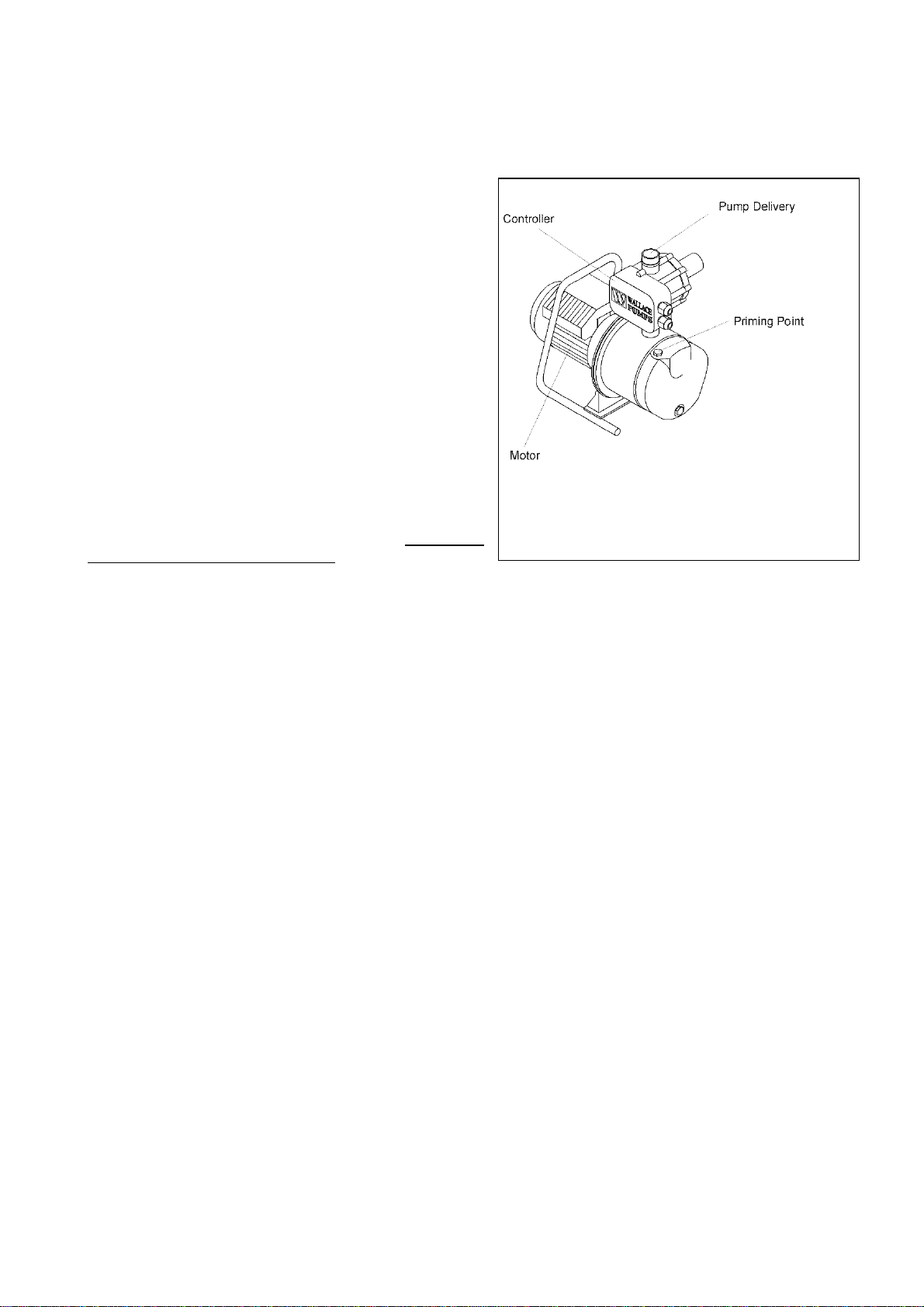
MPEP3000, MPEP5000, HJ60, HJ100, HJ140 WITH CONTROLLER
The controller may have three LED lights (certain models) which when lit, indicate the following functions:-
POWER ON ( green colour ) There is power to the controller
PUMP ON ( yellow colour ) The pump is operating
FAILURE ( red colour ) There is a system or pump fault. System faults may include: the pump is not
fully primed, there has been a run dry e, there is a suction or delivery pipe restriction.
When the pump is first turned on it may run for approximately 0 seconds and turn off, the failure LED will be lit. This
indicates that the pump is not fully primed and has been stopped by the controller as it has sensed a run dry
condition, repeat priming procedure, press the reset button to reset the controller. Repeat until the priming is
completed and pump runs and stops normally. The controller is not serviceable, it is protected by an anti tamper
seal, if broken the warranty is invalidated. As the motor and controller are electrical devices they may be damaged
in the event of a power failure or lightning strike, if this is a risk for your installation we recommend that a suitable
protection device be installed in the power supply to the pump.
If the controller has only a restart button and will not work, check the fault finding instructions.
RESET / RESTART button resets the pump after it has tripped due a fault such as loss of water supply. After
the fault has been rectified press the reset / restart button to start the pump. Do not press the reset button and
operate the pump for more than two times without checking and recifying the cause of the trip. Refer to fault
finding later in these instructions.
HJ60PT, HJ100PT Pressure Pumps with Pressure Switch
Thesepumps DO NOThave power,operation or faultdisplay. Always approach these pumps as being live electrical
equipment. Take care to turn off power if work is being attempted on pump motor or pressure switch.
FAULT FINDING MPEP3000, MPEP5000, HJ60, HJ100, HJ140:
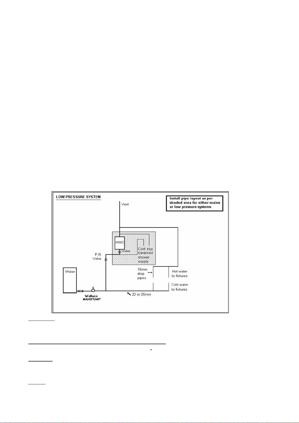
Note: - Not all pumps have a pressure tank. If not, ignore pressure tank points.
Priming trouble: ( Red failure light if applicable, is lit )
DO NOT RUN THE PUMP DRY. Do not press reset button more than twice without checking pump has water in it
and remedying the fault.
1. Air leak in suction pipe system.
2. Foot valve not fully submerged. Or no water in the supply.
3. Suction lift too high, check pump level above the water supply to the pump.
4. Foot or check valve leaking, or jammed.
5. Suction valve is blocked, closed, leaking air or faulty.
Motor switching on and off when no water appears to be being used:
1. Leak / s in suction and / or delivery pipework.
2. Foot or check valve leaking, or not installed, or installed in the wrong place.
3. ( IF FITTED ) Pressure tank air charge pressure incorrect, too high or low. Refer to previous section.

G:\INSTRUCT\MERCHANT\MAXIPUMPS\MPEP3000 MPEP5000 Hydrojet Instructions 06-05-2019.docx
4. Either the hot water cylinder pressure reducing valve and / or the cold water expansion valve and / or the
TPR valve are leaking or incorrectly set.
5. Toilet cistern flush valve leaking.
6. Non return valve in the pump Presscontrol leaking.
Motor switching on and off frequently when water is being used:
1. Blockage or restriction in the outlet, particularly the toilet cistern valve, or ball cock in header tanks.
Pump not switching off or taking more than 20 seconds to switch off after all outlets closed:
1. Pressure tank air charge pressure incorrect, too high or too low, should be 200 kPa ( 30 psi ). Refer above.
2. Drop in tank / bore / well suction water level, or no water in water tank.
3. Leak / s in suction and / or delivery pipework and / or controller non-return valve.
4. Blockage or debris in the presscontrol. Fit a suction strainer to prevent this.
Pump will not start or run:
1. Check controller “ POWER ON “ LED is lit if applicable, or check power supply at the power point with
another applianceyou know works eg: hair drier.
2. Motor thermal cut out has tripped. Switch power off and eliminate cause of trip, wait for cut out to
automatically reset when motor cools, this can take up to 40 minutes.
3. One or more outlets is more than 13 metres above the pump. Call Wallace Pumps.
4. Controller has activated due to run dry. Restore water supply or system fault and prime pump, press reset
button to reset the controller. Refer to priming above.
5. Controller has a blocked port or is faulty, refer to controller section earlier.
6. The run dry “failure” protection has activated and prevented the pump from operating. Find cause and press
reset button. See 7 below.
7. The pump is not turned on at the motor terminal box, some models have a switch on the terminal box.
8. The pump is jammed. Turn off power to pump, check pump is free to rotate by turning motor fan. If jammed
call Wallace Pumps service agent. Debris is the most likely cause.
FIGURE 5
SHOWERS : Pressure fluctuation in a shower need not be a problem!
An avoidable complaint about pump systems is the difficulty of achieving even water flow and temperature in
showers. Our experience is that this is usually due to under size piping, incorrect pipe layout or both.
MAINS PRESSURE or LOW PRESSURE WATER HEATERS
Wallace MPEP3000, MPEP5000, HJ60, HJ100, HJ140 pressure systems are suitable for either system.
GENERAL
Plumbing must be in accordance with the Building Code and any relevant manufacturer’s requirements.
Whichever system you choose the following guidelines will help you to achieve a very satisfactory result
PIPING
All pipe and valve sizes are stated as minimum internal diameter.
The suction pipe and valving between the water supply and pump must be as specified.

G:\INSTRUCT\MERCHANT\MAXIPUMPS\MPEP3000 MPEP5000 Hydrojet Instructions 06-05-2019.docx
The delivery pipe from the pump to house must be 25 mm or bigger as specified.
Bigger pipe sizes are better than smaller, because they provide lower water velocities, which are quieter and have
a consequently lower pressure loss, which means more flow and pressure at taps and showers.
All house piping must be 20 mm minimum except for individual 15 mm droppers to each individual fixture, the 15
mm droppers must not exceed 1.0m in length, and dropper lengths over 1.0m must be 20 mm pipe.
Clip pipes carefully and silicone around them where they pass through walls etc. This will help prevent noise and
vibration.
The system diagram above gives equal hot and cold water pressures to shower at all times.
Which ever system you choose, low or mains pressure, separate shower hot and cold water pipes must be the first
run from each side of the hot water cylinder to the shower mixer with no branches to any other fixture as shown in
the above diagram. Also refer to the hot water cylinder manufacturers piping instructions.
It is unfortunate that people try to save a small amount of money on their piping, because under size piping will
cause; excessive pressure loss and poor flows, along with pressure and temperature surges in showers. Correct
piping sizes and layout will eliminate these problems, and give you the best performance from your pump.
A solution to an existing problem that can sometimes be employed is to run a 25 mm pipe around the house, and
have two 20 mm connections from this 25 mm pipe into the house piping at points nearest to, and furthest from the
pump. This solution can be applied to any system, and is especially good for large single level homes where piping
lengths through the house can be very long.
Regular Servicing
Ensure isolation and disconnection of the power supply to the pump before and whilst carrying out any servicing
work on the unit. Also ensure no liquid will flow into it during servicing.
For this product to meet its expected lifetime please ensure it is installed by a qualified technician and
following maintenance schedule must be followed. A record of by whom and when the maintenance was
completed to be kept and that need to be provided to us when asked for.
a) The pump must be serviced at regular intervals by Wallace Pump’s authorised Service Agent or a qualified
technician who understands the product operation and maintenance.
b) The maximum interval between services should be 12 months.
c) All Alarm activation occurred to be noted as to when (date & time) and how and who rectified it and what
was the reason.
Following (minimum but not limited to) servicing / maintenance work to be done by technician during every service
call and records must be kept with signature of the servicing person, date of servicing and actual work done and
observations.
- Observation of pump operating and start pressure.
- Check water supply tank (if applicable) for solids contamination that may foul pump suction.
- Check weathertightness of pump enclosure.
- Record if any part was changed / replaced and why.
Ensure isolation and disconnection of the power supply to the pump before and whilst carrying out any servicing
work on the unit. Also ensure no liquid will flow into it during servicing.
Modifications or Repairs: Wallace Pumps does not warrant for any damage to the unit or any other property
caused by any un-authorised modifications/repairs in contravention with the Company's instructions or by use of
materials or fittings not supplied by Wallace Pumps. Where a claim arises, we suggest you contact the installer for
rectification.
This manual suits for next models
6
Table of contents
Other Wallace Pumps Water Pump manuals
Popular Water Pump manuals by other brands

Richter
Richter SCK Series Installation and operating manual

Pfeiffer Vacuum
Pfeiffer Vacuum UnoLine UNO 200 operating instructions

Becker
Becker DT 4.6/0-61 operating instructions

GORMAN-RUPP PUMPS
GORMAN-RUPP PUMPS 03E1-B Installation, operation, and maintenance manual with parts list

Everbilt
Everbilt AUTOJ100A2 Use and care guide

Wilo
Wilo Wilo-Helix V ATEX Installation and operating instructions