Wallace Pumps MULTISAN PRO User guide

G:\INSTRUCT\MULTISAN PRO\Multisan Pro Instructions 251119.docx Page 1
MULTISAN‐PRO
Automatic toilet and waste water collection tank and electrically operated macerator pump system.
INSTALLATION AND SERVICING INSTRUCTION MANUAL
PLEASE READ ALL INSTRUCTIONS PRIOR TO PROCEEDING WITH ANY WORK
A permit may be required. Check with the plumbing, drainage and/or electrical inspectors before installation.
Local regulations may stipulate additional installation requirements.
You must consult with your local plumbing and drainage inspector for a permit approval.
AFTER INSTALLATION, THE INSTALLER MUST HAND THIS MANUAL TO THE OWNER
FOR THE PROPER OPERATION AND MAINTENANCE OF THE MULTI-SAN
Failure to do so will result in the installer being made liable under the current legislation for any future claims
resulting from any incorrect operation or servicing.
Congratulations on your purchase of Multisan-Pro wastewater package pump. For this product to meet its
expected lifetime please ensure it is installed by a qualified technician and follow the maintenance
schedule as detailed in section 13.2. Please keep a record of by whom and when the maintenance was
completed, that need to be provided to us when asked for.
PAGE INDEX
Section
1. General view and connections .................3
2. Waste water connections/ Shower/Bath.....3
3. Product overview .....................................5
4. Applications .............................................5
5. Features & benefits ..................................6
6. Pump hydraulic capability............................6
7. Warning: for your safety ..........................7
8. List of fittings supplied & extra may require.7
Section
9. Alarm & solenoid valve system….. 7/8
10. General installation aspects & electrical data.9
11. Pump Operational Logic...............................10
12. Specific Installation (High Temp/remote).10/11
13. Care and servicing……….............................11
14. Warranty & Limitations……………………….12
15. Fault Finding chart ...................................12/14
16 Spare parts drawing & list..........................15/19
Limitations: We reserve the right to change these instructions and improve the product without prior notice.
AUCKLAND WELLINGTON CHRISTCHURCH
55 MAURICE RD, PENROSE 35 BUCHAN ST
PO BOX 12 387 SYDENHAM
PH 09 622 9100 PH 027 543 8634 PH 03 365 6453
FAX 09 622 9119 FAX 03 366 6995

G:\INSTRUCT\MULTISAN PRO\Multisan Pro Instructions 251119.docx Page 2
Figure 1: Dimensions
Figure 2: Cut-away view
Cut-away view through the cover showing the dry mounted pump and motor unit, mounted on a sealed gas and water-tight
collection tank, and the pan connection on the side of the tank.
Sealed lid
Dry mounted pump and
motor unit
Toilet pan connection
Gas and watertight
collection tank
Pump cover
Manual Run / Reset
Button
Tank Vent provided with Carbon / Use this port in
case need to vent outside via vent pipe. Do not
use any air admittance valve e.g. Hunter valve
2 off 40mm ports to
connect 40mm waste pipe
from WHB, Shower / Bath,
Sink, etc.
Identical 2 off 40mm Port
are provided on the other
side of the unit
2 off fastening
safety screws. Undo these
to remove pump cover.
Ensure Power supply to
pump is switched off &
plug is removed

G:\INSTRUCT\MULTISAN PRO\Multisan Pro Instructions 251119.docx Page 3
1. GENERAL VIEW & CONNECTIONS
Figure 3: General view
NOTE: - The Multisan-Pro pump unit MUST be installed in dry weatherproof, non-floodable location with easy access
for operation, maintenance and repairs. Any damage to pump unit or any other item due to non-compliance of this
clause or any other instructions in this manual is not covered under warranty.
1a.Cover for dry mounted pump, motor and controls. Remove the fastening safety screw holding cover to tank and then pull and
lift to remove.
1b.Collection Tank - Fittings supplied may be shipped inside. Please check carefully in the tank and remove all fittings / parts.
Any fitting / part left in tank will damage pump. Do not subject the tank to impacts, scratches, scouring or any drilling that may
weaken it.
2. Inspection lid - Screw in with o-ring seal; turn anti-clockwise to open. Install upright with the inspection lid on top.
3. Pan connection - Only one WC pan connection is provided and is allowed per installation.
The standard vitreous P type pan discharge to be connected directly to the tank at pan connection provided on tank with
suitable rubber gasket. Do not damage the raised lip and groove. Wet the gasket with soapy water before fitting to make fitting
easier. If bends are unavoidable, keep to a minimum and use only swept inspection bends.
4. Pump delivery - 32 mm BSPF with gasket. Use PVC pressure pipe. Recommend to install a Mac union connector close to
the pump, then the 32 mm solvent weld end swing check valve (9) and then 32mm solvent weld end isolating ball valve (10)
to allow for future maintenance. Securely strap and isolate the pipe from the building structure to prevent vibration or noise
transmission during operation. Any horizontal section of the delivery pipework should always have a continuous rise towards
the soil or waste pipe connection. It should never be level or have a fall.
5. Tank vent connection - 40 mm moulded Vent connection with carbon is provided on the tank for localised venting. If outside
vent is required as per local rules & regulations, remove the carbon vent, floating ball & gasket inside the moulded vent
connection. Insert the 40mm PVC fitting provided in the rubber sleeve. Use 40 mm pipe to run the vent to a termination point
in accordance with the Building and Plumbing Code. Do not use an air admittance valve, e.g. a "Hunter Valve".
6. Shower / Bath connection - One special 40mm connection with one way valve is supplied as fitting. This need to be used
for connecting a shower or a bath to pump unit. Refer photos below for details. This should not be shared with any other
connecting fixtures or appliances. If both are connected, each must have its own valve. The extra connection can be purchased
from Wallace Pumps if required. This connection is 100 mm centre height from the base floor level. The inlet pipe must be
properly braced to prevent the water pressure from dislocating the push-fit connection. The shower tray or /and bath outlet
must be minimum 180mm from base floor level height. Distance between the pump and the shower or/and bath will decide
the height of the shower or /and bath outlet to achieve pipe fall from shower or bath to pump as per building & plumbing code
/ regulations.
1a:- Pump Cover
1b:- Collection Tank
2:- Inspection
lid
3:- Pan connection
4:- Pump delivery
5:- Tank vent
ti
6:- Shower / Bath connection
7:- Additional Inlet
ti
WARNING – Pump
Cover is not water
tight. Water dripping
on to Pump Cover
may cause pump
failure and hazard.

G:\INSTRUCT\MULTISAN PRO\Multisan Pro Instructions 251119.docx Page 4
7. Additional inlet connection - One special 40mm connection with one end as spigot & other end as socket is supplied as
fitting. This need to be used for connecting a WHB or a Sink or any other waste water outlet to pump unit. Refer photos below
for details. The extra connection can be purchased from Wallace Pumps if required.
8. MANUAL RUN / RESET button – Provided on the pump cover under a clear plastic bubble. Refer figure 2 page 2. Pushing
& holding this button will enable motor to run as long as the button is held push down. In case of alarm trip same button will
reset the trip provided the trip reason is resolved. Exercise extreme care. Call a service agent if the motor continues to trip.
9. A Wallace 32 mm full flow non-clog swing check valve with solvent weld ends suitable for PVC pressure pipe is provided as
one of fittings. This should be installed in the delivery pipe in a vertical position within one metre (pipe length) of the unit to
stop backflow of liquid from the pipe back into the collection tank.
10. Isolating Ball Valve - A 32 mm full flow Isolating Ball valve with solvent ends suitable for PVC Pressure pipe is supplied for
installation after the 32 mm non-return swing check valve.
11. Labels - Labels Warning against inappropriate dumping of non-organic products such as condoms, sanitary pads, wet
wipes, tampons, nappies, sand, stones, tar, cement, coarse paper, non-water-soluble paper towels, cardboard, plastic
bags, fat, oil etc. in the toilet, to be affixed to appropriate fixtures & appliances.
Pumping of these products may cause pump unit to malfunction or jam. Any damage to pump or any other property or
person due to such jam is not covered under warranty.
2. TYPICAL WASTE WATER CONNECTION DRAWING WITH SHOWER TRAY/BATH WASTE HEIGHT
Refer below typical connections shown connected to pump unit. If in doubt please call Wallace Pumps for further details.
Shower Tray or Bath Waste Height:
Refer above schematic drawing. When pump & shower and/or bath are in same room, the advised minimum height of the shower
tray waste discharge point is 180 mm above the MULTISAN-PRO floor level. The final height is determined by starting from the
MULTISAN-PRO Bottom inlet connection at 100 mm centreline and work back to the shower tray discharge point at the minimum
pipe fall rate as per building & plumbing code. Add the necessary height for the trap to give you the total height from the floor to
the shower tray.
Pipe Sizes
PAN discharge pipe if direct pan connection Not required
DRAIN from shower and bath to MULTISAN-PRO special fitting with NRV 40mm Waste Pipe
DRAIN from vanity, W/M, Kitchen sink to MULTISAN-PRO special fitting40mm Waste Pipe
VENT from MULTISAN-PRO to approved termination (If required) 40mm Waste Pipe
PUMP DELIVERY from MULTISAN-PRO to approved termination 32mm PVC Pressure Pipe

G:\INSTRUCT\MULTISAN PRO\Multisan Pro Instructions 251119.docx Page 5
3. PRODUCT OVERVIEW
The MULTISAN-PRO pump is designed for the disposal of sewage, water soluble toilet paper and waste water. It is not designed
as a sanitary waste disposal unit or a kitchen waste macerator unit, although it will pump the effluent from the latter. Avoid
dumping in toilet or WHB or Sink non-organic products such as condoms, sanitary pads, wet wipes, tampons, nappies,
sand, stones, tar, cement, coarse paper, non-water-soluble paper towels, cardboard, plastic bags, fat, oil etc. These
products will cause the unit to malfunction or jam. Any damage to pump or any other property or person due to such
jam is not covered under warranty.
This unit is a secondary system, it is notintended for use as the only means of effluent disposal from a dwelling, and there
must be an alternative gravity flow system available to the users of this pump. For complete household or commercial duties
refer to our Wallace Pumps Sanipower, Saniboy or Sanistar range of packaged pump stations.
The WALLACE MULTISAN-PRO collects the gravity fed waste liquid into its collection tank. When a set water level is reached,
the micro pressure switch inside the collection tank automatically activates the powerful quiet pump equipped with a cutter blade
and an open impeller to deliver the effluent under pressure to the desired location through a 32 mm internal diameter pipe.
Because of the small pipe size, the delivery can be run virtually anywhere and in any direction,
- Through walls,
- Through ceiling spaces,
- Under floors,
- Around and over obstacles.
The unit enables the installation of a variety of equipment where this was previously impossible due to economic constraints,
physical limitations, or because there was no unit available with adequate performance. The MULTISAN-PRO has been developed
to overcome these problems, including
- Below sewer-line installations,
- Where gravity fall is not possible,
- Physical restrictions, e.g. concrete walls or concrete floors,
- Where new pipes cannot be run under the floor, such as concrete floors,
- Where large diameter 100 mm gravity lines are not appropriate for the location,
- And many other situations.
4. APPLICATIONS
The MULTISAN-PRO collects and automatically pumps away toilet waste water from the following and many other typical
applications:
- Basement toilet and bathroom facilities
- Secondary amenities in factories built on concrete floor slabs
- Relocated bathrooms where gravity fall to existing sewer connections is not possible
- Re-developed apartment blocks in inner cities
- Master bedroom ensuites
- Executive bathrooms
In addition to the toilet pan (only one allowed per installation), you can connect one or a combination of the following additional
fixtures or appliances:
- Laundry tubs,
- Domestic clothes washing machines,
- Domestic sinks with or without waste disposal units,
- Domestic dishwashing machines,
- Bar facilities without high temp water discharging Glass washers or commercial dishwashers
- Bath, shower, vanity,
PROVIDED THAT
- In a multi-storey construction, they are all located on the same floor level as the MULTISAN-PRO.
- Maximum temperatures in the collection tank are 40C continuous and 60C intermittent.
- No unwarranted items (listed under “Section 2 Product Overview”) are discharged into unit
- The max flow of water discharged into the unit should not exceed 70 L/min.
For larger flows, contact Wallace Pumps for advice.
Caution Note: - Pump as it is not suitable for following. Please contact Wallace for suitable solution
- Condensate water from air conditioning unit.
- Hot and/or cold water from relief valve and/or cold water expansion valve from hot water cylinders.

G:\INSTRUCT\MULTISAN PRO\Multisan Pro Instructions 251119.docx Page 6
5. FEATURES AND BENEFITS
FEATURES BENEFITS
Higher pump head ( longer run & higher vertical height ) Pumps higher and further
Higher flow rate Empties faster and accepts multiple discharges
Dry mounted motor and pumping unit Easier to clean and service and more reliable
Heavy duty motor in hard alloy casing Longer lasting
Heat and overload protected motor Reduces risk of costly burnt-out motor
Robust cutter/slicer ahead of "Open" impeller Cuts through most soft sewage & waste
One piece collection tank No weak joints
Multiple entry options into the tank Can service many utilities from many directions
Pan entry 180mm high with rubber gasket Caters for standard P type WC pans
Option of delivery pipe directions on either side of tank Flexible arrangement to suit site conditions
6. PUMP HYDRAULIC CAPABILITY
To ensure that the MULTISAN-PRO is suitable, check your installation requirements against the dimensions and hydraulic
capabilities of the unit.
-This graph is based on a flow of 35 litres /min. If flows exceed 35 L/min please contact Wallace Pumps for assessment.
-Measure the overall height of the delivery pipework (from the bottom of the tank to the highest point in the
delivery line, also referred to as Static Head).
-Measure the total run of all vertical and horizontal pipes from the pump to the sewer drain.
-Count the number of bends in the pipeline. For each bend add 1m to above measured length of pipe.
-Work out total length of pipe = Pipe length (Horizontal + Vertical) + 1m X No of bends.
-Use the graph below to make sure the Total Run of Pipe and Static Head intersect below the line of your pipe size.
-Ensure system curve falls within the requirement which will ensure pump is suitable for application.
-In case of doubt call Wallace pumps and get confirmation that pump is suitable for your application.
0
1
2
3
4
5
6
7
8
9
10
0 20 40 60 80 100 120 140 160 180
STATICHEAD(m)
METRESTOTALRUNOFPIPE
WALLACEMULTISANPROSELECTIONCHART
32mmpipe
25mmpipe

G:\INSTRUCT\MULTISAN PRO\Multisan Pro Instructions 251119.docx Page 7
7. WARNING: FOR YOUR SAFETY
The MULTISAN-PRO unit requires a power supply rating of 230 Volts 50 Hz single phase.
This apparatus must be earthed. To ensure safe operation, check that the three pin power point is earthed and protected by a
fuse or ELCB protection of an appropriate rating.
Also check with your local power supply authority. Their requirements may be additional to and over-ride those listed above and
in section 8.3.
When opening the cover or inspection lid, always switch the power off and ensure no liquid flows into the tank. Always re-install
the cover and fasten the safety screw on the cover to comply with electrical regulations.
To prevent shock or fire hazard, do not expose this unit to rain, any type of moisture, flooding or overflows.
The wires in the main connection plug are coloured in accordance with the following code:
Earth: Green/Yellow Neutral: Blue Phase: Brown
8. LIST OF FITTINGS SUPPLIED WITH UNIT & OTHER ITEM THAT MAY REQUIRE TO BE ARRANGED BY
INSTALLER.
8.1 Unpacking And Inspection. Items supplied with the unit.
(Some parts may be delivered inside the tank, access via the inspection lid).
Your MULTISAN-PRO package should contain the following items
1 x WALLACE MULTISAN-PRO pump unit
1 x Special 40mm DWV pipe connection with “one way check valve” for connecting shower or bath waste
water pipe.
If above additional fitting is required can be purchased from Wallace Pumps
2 x Special 40mm DWV pipe fittings with one end spigot (connecting to pump) & other end socket to connect
waste pipe from WHB, Sink, or any other domestic appliance and to connect 40mm DWV pipe as vent
connection if required as per local rules and regulations.
If above additional fitting is required can be purchased from Wallace Pumps
1 x Toilet pan rubber seal
1 x 32 mm PVC swing check valve with solvent weld ends suitable for PVC Pressure Pipe
1 x 32 mm PVC isolating ball valve with solvent weld ends suitable for PVC Pressure Pipe
8.2 Additional items (to be arranged by installer) that may require for correct installation of unit
Additional materials you may require from your plumber/installer or local plumbing or building merchant:
40mm PVC drain waste pipe into the MULTISAN-PRO.
40 mm PVC waste pipe and PVC cowl for the vent from the collection tank
32 mm Class B or D or 4.5 PVC pressure pipe for the delivery pipe
PVC pipe, connector fittings and swept inspection bends for the toilet pan as required
PVC fittings and cement as required (bends, sockets, traps and waste strainers etc.)
PVC pipe "lubricant" (do not use petroleum based products)
Thread tape - do not use hemp. Silicone sealant.
9. RECOMMENDED ALARM SYSTEM - AUTOMATIC WATER SHUTOFF SYSTEM VIA SOLENOID VALVE.
9.1 Optional Extra system that may require as per Local Rules & Regulations.
Optional Alarm System with automatic water shut off system via Solenoid Valve may require as per local rules and
regulations.
This is available as extra from Wallace Pumps.
Following items will be required for each pump.
1 X Water Monitor Unit, Part no “SFMONITOR”
1 or 2 X 20mm Normally Closed, Brass Solenoid Valves with 24V AC coil, Part No “72218”
Refer next page for full wiring diagram and connection details of the system.

G:\INSTRUCT\MULTISAN PRO\Multisan Pro Instructions 251119.docx Page 8
Optional Alarm System with automatic water shut off system via Solenoid
Valve may require as per local rules and regulations. Please Check!!!
Wiring Diagram & connection details for “Water Monitor”
used as “Alarm” and / or water shut off system via “Solenoid Valve/s” and /
or “Washing M/C turn off” System on “MULTISAN-PRO” Pumps.
Connect 230V, 1Ph,
10A, AC Mains Power
Supply to Pump from
Separate power
point
If Washing M/C OR
Dishwasher needs to be
stopped on Alarm
mode, connect “230V
AC OUTPUT POWER”
Phase “P”, Neutral
“N” & “Earth “E” from
Water Monitor to the
Machine. Max load
allowed is 10 Amps,
1.5kW.
Connect 24 V AC coil of
Solenoid Valve/s (Max 2
Valves) to “24 V AC
OUTPUT POWER”
terminals “V1” & “V2” of
Water Monitor with
3CX1.5mm2 or bigger
cable. (Check with
Wallace). Earth wire to be
connected to “Earth”
terminal “E” as shown
.
Volts Free Contacts in the
circuit board which
activates in case of Alarm
Connect Volts
Free Terminal No
1 (com) & No 3
(N/C) to
“L1” and “L2”
Terminals on
Water Monitor as
shown.
Ignore No 2 (N/O)
24 V AC coil
Solenoid Valve/s
(Max 2 allowed)
can be installed
in Cold &/or Hot
water (max
55Deg C) supply
line supplying
water to
amenities
generating
wastewater
being pumped
by the pump.
These valves
will close on
Alarm situation.
V
olts free
Terminal
1 (Com)
V
olts free
Terminal
2 (N/O)
V
olts free
Terminal
3 (N/C)
MULTISAN-
PRO Pump
Photo of Circuit board with terminal
details under the cover
WATER MONITOR
Supplied loose to be installed in Dry,
Moisture Free, Ventilated, visible place
with easy access for operation,
maintenance & servicing.
Terminal details of
WATER MONITOR
Connect 230V, 1Ph, 10A, AC Mains Power
Supply to Water Monitor. Connect to
“230V AC INPUT POWER” Phase “P”,
Neutral “N” & Earth “E” terminals as
shown.

G:\INSTRUCT\MULTISAN PRO\Multisan Pro Instructions 251119.docx Page 9
10. GENERAL INSTALLATION ASPECTS AND ELECTRICAL DATA
10.1 General
1. Where a permit is required, it is required that the unit should be installed by a registered plumber and the power supply should
be connected by a registered electrician. It is the responsibility of the installer to obtain all the necessary permits and consents.
Ensure full compliance with all applicable local regulations. The owner or owner's agent must ensure that the MULTISAN-PRO is
compatible with the existing or proposed plumbing system design.
2. The installation of the unit and non-return and isolating valve must comply with the following conditions:
- They are easily accessible for servicing;
- Service fixtures and appliances located on the same floor level as the unit, each must have a waste trap installed.
- Pump is in a clean, dry, non-floodable position, protected from UV and on a permanently sturdy support;
- Design against overflow, flooding or unwarranted children interferences or excessive moisture;
- Protect from freezing of liquids in the unit and the pipework;
- The tank is installed with the screwed inspection lid on top;
- Install an individual special 40mm DWV pipe connection with “one way check valve” for the shower tray & bath
- All the requirements in these instructions are met.
3. Any modifications not described in this manual and without written authorisation by a Wallace representative will
nullify the Wallace Pumps warranty and durability compliance.
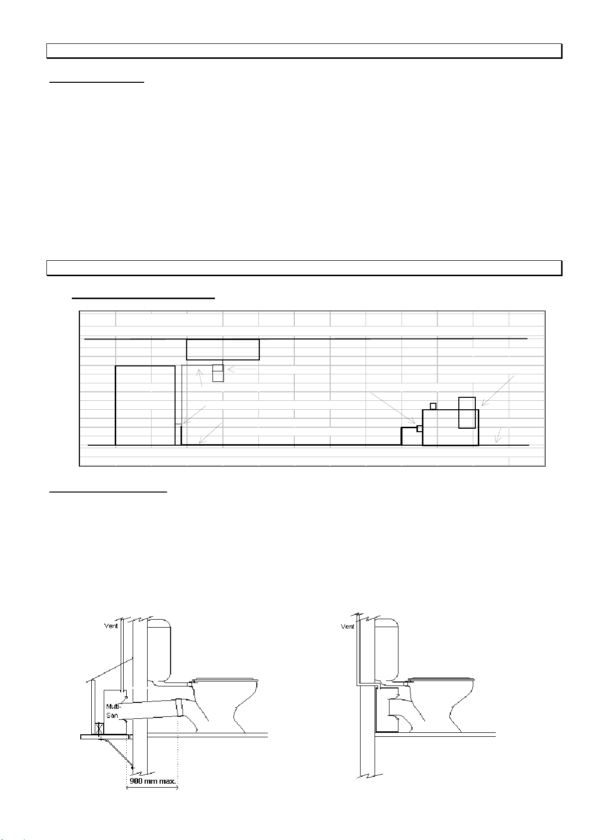
10.2 Plumbing
1. The connection to the soil and waste drain system must be carried out in accordance with the Building and Plumbing Code.
The connection of the unit's delivery pipe to a soil or waste pipe should be kept at least 0.5 metre distance from any other
connection. Also it must not be connected in a section of the pipe which runs the risk of being flooded creating a back pressure
down the pipework to the unit. The connection point is usually 600 mm above the lowest W.C. connection or the lowest gully trap.
The connection of the delivery from the unit to a soil or waste pipe should be a swept inspection bend in the direction of flow of
the soil or waste pipe.
2. Any horizontal section of the delivery pipework should always have a continuous rise towards the soil or waste pipe connection.
It should never be level or have a fall. The pipework must be securely strapped and isolated from the building structure to prevent
vibration and noise transmission.
3. Install only the supplied full flow non-clog swing check within one metre of the pump in a vertical position, below and close to
the supplied isolating ball valve.
5. All pumped appliances, such as washing machines and dishwashers, must discharge via an approved waste system which
includes an air gap and a trap.
6. Ensure that the 40 mm tank vent to outside (if required) is installed in the top of the unit and that it extends full-bore to the
external air (the minimum height must be 50mm above the overflow level of the highest fixture discharging into the WALLACE
MULTISAN-PRO) or terminated elsewhere as described in the current Building & Plumbing regulations. DO NOT use air
admittance e.g. a "Hunter Valve" venting devices as they do not let air out of the tank.
7. It is important from a health and safety reason and for the protection of property, that an overflow relief pipe is plumbed and
delivered to a safe and visible area in the event that the discharge flows into the MULTISAN-PRO exceed the pump hydraulic
performance capability or caused by a mechanical failure or a pipe blockage. Pumped appliances and water supply can also be
safeguarded as per Section 9.1.
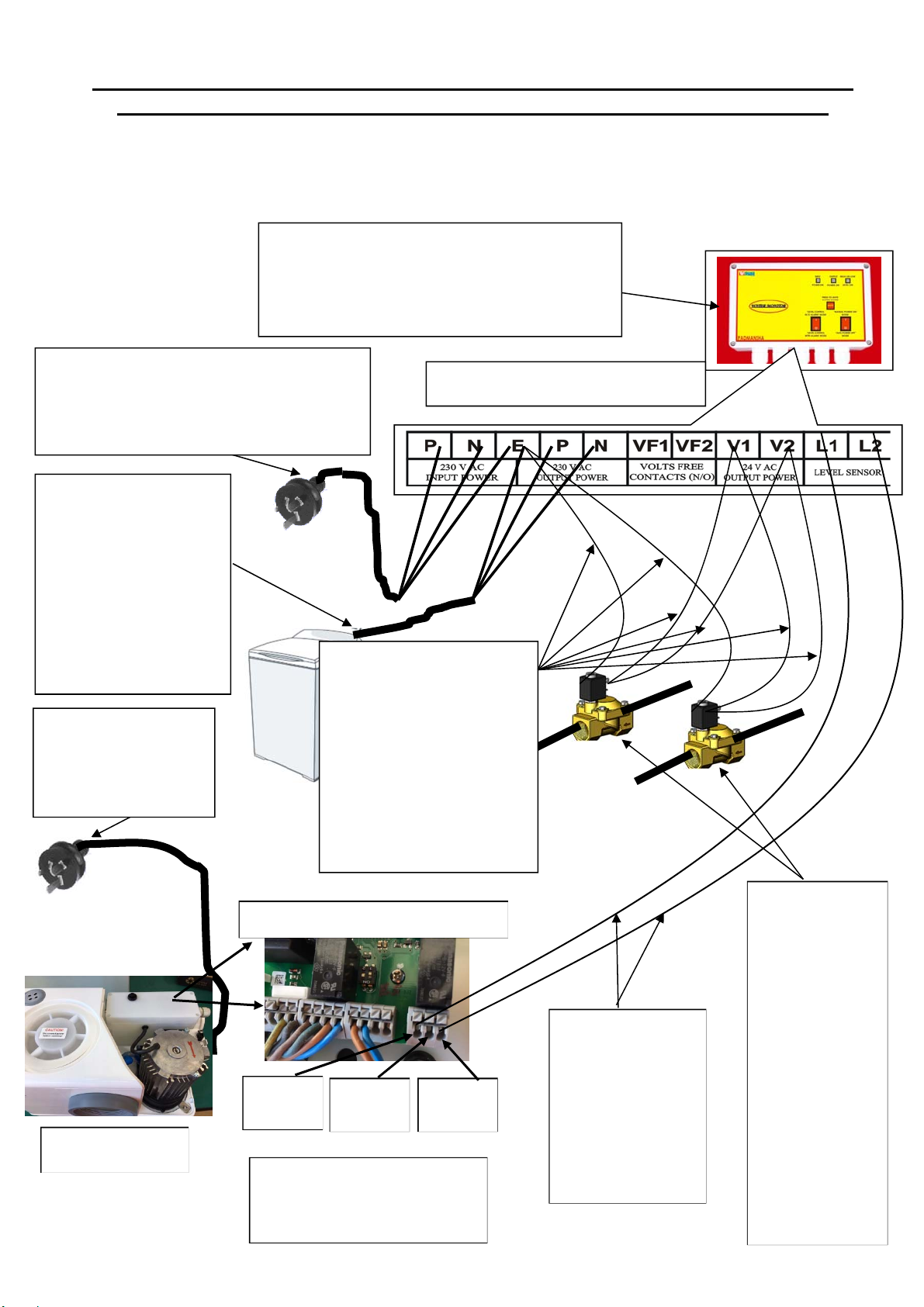
10.3 Electrical Connection
1. The WALLACE MULTISAN-PRO is fitted with a high quality 2900 rpm motor:
Nominal current : 2.5 amps
Motor input : 0.6 kW
Cable : 1.5 metres of 3 core - supplied with the unit
Cable Plug : Standard 3 pin domestic earthed - supplied with the unit
Supply : 1 phase 230 volts 50 Hz.
2. Overload protection (thermal / overload): the unit has a built-in automatic motor overload. In the event of an overload trip, the
pump will not restart automatically as it must be manually reset. Nevertheless always switch off the power in case the fault was
not an overload trip. Then determine and eliminate the cause of the overload. Press the reset button under a clear plastic bubble
to ensure pump operates.
3. Wiring connection: the electrical wiring connection type should preferably be the "Clipsal Permanent Connection Unit with
Neon" type, or PDL 253N, or similar. The permanent connection should be fixed in a position where it cannot be reached by a
person in a bath or shower or standing on a wet surface.
4. The unit requires a domestic 3 pin earthed single phase power supply. The appliance must not be connected to a conventional
plug, socket or adaptor when installed in a bathroom, unless properly protected by an approved earth leakage circuit breaker or
similar.
5. Refer Section 6 (Warning: for your safety) for additional electrical information.
Always refer to your local power supply authority for details of acceptable wiring, as their requirements over-ride the guidelines
above.

G:\INSTRUCT\MULTISAN PRO\Multisan Pro Instructions 251119.docx Page 10
11. PUMP OPERATION LOGIC
11.1: Operation Logic:
When installed & wired correctly, Multisan-Pro unit will operate as below.
1. When pump on/off sensor contacts are CLOSED, pump will start and operate for maximum ten cycles of 30 sec ON, 5 sec
OFF, provided sensor contacts are closed.
If sensor contacts opens after 1 or 2 cycles the pump will not carry on remaining cycles.
2. If the pump on/off sensor contacts remains closed, even after ten cycles by pump, then following things will occur.
- Pump will stop operating.
- Power supply to pump will be switched off from the circuit board.
- Internal Alarm Buzzer will sound.
- N/C Volts Free Contacts will close. If these are connected to Water Monitor & solenoid valve/s, it will activate alarm &
close solenoid valve/s thus shutting of water supply to amenities to avoid flooding.
To Re-set the alarm mode, Press the reset button under a clear plastic bubble on top of pump cover to re-start operating normally.
12. SPECIFIC INSTALLATION PROCEDURES
12.1 High temperature installations
12.2 Remote installation:
If the Pump unit is installed behind the toilet wall or under the toilet floor, then the distance and / or level difference between WC
pan and pump unit should NOT BE MORE THAN 900mm. Suitable access must be provided for operation, maintenance and
repairs of the unit at all times. An adequate overflow outlet must be provided. Our warranty excludes any damage caused by an
overflow. Because of the danger of flooding caused by continued flushing / discharge in excess of capacity or by a malfunction
of the pump, particularly as the operation of the quiet motor outside the room cannot be heard by the occupants or visitors.
Refer in next page typical remote installations. These May be possible with Multisan-Pro unit. However,
please contact Wallace Pumps explain your situation and get approval before remote installing the unit.
Any issues with pump by remote installation Without Prior approval from Wallace will make Warranty NULL
& VOID.
WALLACE PUMPS
HIGH TEMPERATURE / COMMERCIAL INSTALLATIONS WHERE THE LIQUID ENTERING THE PUMP IS OVER 60 DEGREES CELCIUS
SINK WALLACE PUMP MODELS
SANIBOY / SANIMASTER
GREASE TRAP MULTI-FLO / MULTI-SAN
and UNI-SAN
DISHWASHER STANDARD PIPING INLET TO PUMP ( NOTE 1 )
OR WASHING
MACHINE ETC DISCHARGE FROM MACHINE (NOTE 2 )
80 mm COPPER OR PVC PIPE FLOOR LEVEL
MINIMUM TOTAL LENGTH 2 METRES
NOTE 1 INLET LEVEL TO THE PUMP IS TO BE ABOVE FLOOR LEVEL. 180mm FOR SANIBOY/MASTER, AND 250mm FOR OTHERS
NOTE 2 SET THE MACHINE TO MAKE ITS MINIMUM OUTLET LEVEL AT LEAST100 mm ABOVE THE PUMP INLET LEVEL

G:\INSTRUCT\MULTISAN PRO\Multisan Pro Instructions 251119.docx Page 11
These remote installations must have the pan vented as normally required for a gravity flow installation, this vent is not shown
on these diagrams.
13. CARE AND SERVICING OF YOUR UNIT
13.1 Protect the Multisan-Pro unit from weather or flooding or frost. Any damage to unit due to no protection is not
covered under warranty.
13.2 Regular Servicing
Ensure isolation and disconnection of the power supply to the pump before and whilst carrying out any servicing work on the unit.
Also ensure no liquid will flow into it during servicing.
For this product to meet its expected lifetime please ensure it is installed by a qualified technician and
following maintenance schedule must be followed. A record of by whom and when the maintenance was
completed to be kept and that need to be provided to us when asked for.
a) The MULTISAN-PRO pump must be serviced at regular intervals by Wallace Pump’s authorised Service Agent or a
qualified technician who understands the product operation and maintenance.
b) The maximum interval between services should be 6 months (for heavy usage unit) and 1 year (for light to medium usage
unit)
c) All Alarm activation occurred to be noted as to when (date & time) and how and who rectified it and what was the reason.
Following (minimum but not limited to) servicing / maintenance work to be done by technician during every service call and records
must be kept with signature of the servicing person, date of servicing and actual work done and observations.
- The interior of the collection tank and dip tube should be clean from any sludge or muck building.
- Check and ensure pump starts and stops at normal levels and pump out as per site conditions and pump curve.
- Check for any abnormal noise or operation
- Record if any part was changed / replaced and why
Ensure isolation and disconnection of the power supply to the pump before and whilst carrying out any servicing work on the unit.
Also ensure no liquid will flow into it during servicing.
13.3 Modifications or Repairs: Wallace Pumps does not warrant for any damage to the unit or any other property caused by
any un-authorised modifications/repairs in contravention with the Company's instructions or by use of materials or fittings not
supplied by Wallace Pumps. Where a claim arises, we suggest you contact the installer for rectification.

G:\INSTRUCT\MULTISAN PRO\Multisan Pro Instructions 251119.docx Page 12
14. WARRANTY AND LIMITATIONS
The purchaser and / or installer must ensure full compliance with all applicable regulations.
Wallace Pumps does not warrant for any damage to the unit or any other property caused by poor quality installation,
workmanship or installations in contravention with the Company's instructions, or by failure of materials or fittings not
supplied by the Company. The Company does not accept any liability resulting from flooding or from safety breaches,
the user must take the necessary steps to guard against such occurrences.
Subject to the above and where the unit has been installed, operated and maintained in accordance with local plumbing
and electrical regulations and this instruction manual, especially servicing & records as per clause 12.2 page 11 of this
manual, Wallace Pumps warrants the unit for a period of 2 years from the date of purchase, against defects in materials
and workmanship on the basis of return to our distributor's or service agent's premises, freight paid. Contact Wallace
Pumps for a list of names and addresses.
15. Fault Finding Chart
NOTE In the warranty period, any work not described in this manual must be carried out by Wallace Pumps Service Agents,
otherwise your warranty and the product's durability period will be invalidated.
ALWAYS ensure isolation and disconnection of the power supply to the pump before and whilst carrying out any servicing
work on the unit. Also ensure no liquid will flow into it during servicing.
OCCURRENCE POSSIBLE CAUSE
REMEDY
1.
-Motor runs
continuously
without clearing the
liquid.
-Level switch operated by water level
remains in the ON position because :
a. pipework is blocked; or
b. pump is blocked; or
c. tank is blocked; or
d. delivery hose is kinked.
e. pressure switch is water logged
-Check that the pipework is clear.
-Turn off the power and check that the pump can
rotate freely in both directions by turning the
shaft at the top end of the motor with a
screwdriver.
-If blocked, clear the obstruction.
-PVC Pipes are recommended.
2.
-Pump runs but
delivers little or no
liquid.
-Delivery head (combination of vertical &
horizontal pipe lengths, pipe bends and
size) is too high for the unit.
-Check the system against the pump operating
parameters. Refer Section 5 (Building design).
-Check that the pump is not pumping the water
level down too low.
3.
- Pump starts but
takes over 10
seconds to reduce
the liquid level in
the tank
(as seen through
the inspection lid).
-Delivery line is partially blocked or too
small.
-Pump is not venting.
-Tank is not venting
-Inflow rate too high
-Unblock and/or change the pipework to the
minimum ID.
-Visually check that the tank vent pipe is clear;
or by releasing the pipe from the tank and blow
down it; or by removing it and flush clean.
-Check that the tank vent functions correctly:
. Liquid should rise in the vent tube until the
pump starts.
. When the pump runs, little or no liquid should
flow through the vent tube. Remove the
inspection lid to check the return flow into the
tank.
. When the pump stops, the liquid in the vent
tube should draw down to empty.
-Refer fault 9 below.
-Call our office for details of changes to achieve
higher head and pump delivery flow rates.
4.
Motor does not start
at all
-Not connected to power supply.
-Power cut/fuse blown.
-Wrong connection to pressure switch
(always off).
-Connect power.
-Restore electrical supply.
-Check the level switch setting and operation.
Refer fault 9 below.

G:\INSTRUCT\MULTISAN PRO\Multisan Pro Instructions 251119.docx Page 13
5.
Motor does not start
at all and alarm
activates
To reset the alarm
mode, switch power
off and then on.
- Discharge pipe is blocked.
- Pump is blocked.
- Dip pipe is blocked.
- Obstruction in tank.
-Thermal load activated.
- Faulty liquid level switch (always on).
- Check that pipe is clear, check that non-
return valve is operational.
- Turn off the power and check that the pump
can rotate freely in both directions by turning
the shaft at the top end of the motor with a
screwdriver. If blocked, clear the obstruction.
- Check the dip pipe is clear. This can be
done by removing the pressure switch and
using air or pipe cleaner.
- Plastics and paper towels and other large
foreign objects can block the inlet to the pump.
Check there are none of these inside the tank.
- Determine and remove the cause of the
overload trip. Reset the overload button and
test run. If the overload does not start the
motor, leave the unit to cool down for 15
minutes, check fault No 12 and retry. If the
overload re-occurs, switch the power off and
contact a Wallace Service Agent.
- Check the level switch setting and operation.
Refer fault 9 below.
6.
After evacuation the
motor engages
several times
before stopping, or
restarts at intervals
without any liquid
discharged into the
collection tank.
-Water is leaking / back flowing into the unit
from the delivery pipe, triggering the motor
to re-start.
-Non-return valve does not close properly.
-No non-return valve in the delivery line.
-Check that the non-return valve is clear. This
should be the supplied 32 mm FULL FLOW
NON-CLOG SWING CHECK VALVE installed
in a vertical section of pipe as close as
possible (within 1 metre) of the pump.
-Remove the obstruction.
-Install 32 mm full flow non-clog non-return
swing check valve supplied.
7.
Pump runs and
makes a rattling
noise.
Solid object is in the tank or in the pump
and will not pass through the delivery.
Clear the obstruction.
8.
Unit smells.
-Inadequate water leading to clogged
up/dirty unit.
-No water seal on waste pipes to the unit.
-Activated carbon in carbon vent (if fitted) is
no longer functioning.
-Flush unit out with a bleach solution and
clean water.
-Plumb waste water traps.
-Replace activated carbon with new from
Wallace Pumps
9.
Pump does not
start or stop at the
correct levels of
liquid in the tank.
-Tank not correctly vented.
-Faulty liquid level switch
-Liquid level dip tube or pressure switch
blocked
-Unscrew tank inspection lid to allow venting.
Switch power on and operate pump. If
operation is correct, switch off power and
check tank vent is clear or fit vent according to
Section 8.2. Replace inspection lid.
-Replace the level switch.
-Remove obstruction and recheck operation.

G:\INSTRUCT\MULTISAN PRO\Multisan Pro Instructions 251119.docx Page 14
1
0.
Liquid leaks from
the unit.
-Loose pipework connection.
-Faulty liquid level switch.
-Mechanical seal fault (leakage between
motor and pump).
-Leakage from the seal gasket between the
pump and the tank.
-If unit is of 15 years plus corrosion of pump
volute may occur. If unit is on brackish
water this corrosion can be accelerated.
-Tighten the pipework connections.
-Check and replace if required.
-Check and replace if necessary.
-Check the condition of the seal. Replace if
necessary. If necessary, run a small bead of
neutral cure silicone sealant rated at 100
degrees Celsius on both sides of the gasket.
-Check and tighten the 6 nuts to the tank.
-Check there is adequate pressure on the
seal. Do NOT over tighten.
-Replace pump/motor with new from Wallace
Pumps.
1
1.
Waste water builds
up in the shower
tray.
-Air lock because connection is made into
the small raised tank chamber under the
cover.
-Power is off.
-Overload trip.
-Inflows exceeding pump capacity.
-Blockage in the pipework.
-Shower pipe also has other pipes
connected to it.
-Pump malfunctioning.
-Overflow pipe (if applicable) is blocked.
-Shower tray height is too low.
-Reconnect the pipe into the walls of the
collection tank at other end.
-Check power supply and fuse.
-Lift cover and press Reset button. If unsure or
if the motor trips again, call a service agent.
-Check system against pump operating
parameters. Refer Section 5 (Building
Design). Temporarily, turn off discharging
appliance.
-Find and remove blockage.
-Separate the shower waste pipe.
-Refer above faults and rectify.
-Unblock the overflow pipe.
-To ensure safe operation of shower the tray
should be 180 mm above the base level of the
Multisan.
1
2.
Motor hums/buzzes
but does not appear
to run.
-Foreign body blocking the impeller.
-Electrical fault.
-Faulty liquid level switch.
-Remove obstruction from the pump. Check
freedom of operation as per fault 1 above.
-If there is no obstruction and the rotor turns
freely, then the motor is possibly faulty. Refer
to a service agent.
-Check the level switch.

G:\INSTRUCT\MULTISAN PRO\Multisan Pro Instructions 251119.docx Page 15
16. Spare Parts drawing & list
pump unit

G:\INSTRUCT\MULTISAN PRO\Multisan Pro Instructions 251119.docx Page 16
Complete lifting unit

G:\INSTRUCT\MULTISAN PRO\Multisan Pro Instructions 251119.docx Page 17
Circuit board

G:\INSTRUCT\MULTISAN PRO\Multisan Pro Instructions 251119.docx Page 18
assembly drawing
no. Qty nomination Article
numb
er
assembly
lifting unit 1.0
1.0 1
1 Assembly unit complete Microboy E3
Assembly unit complete Microboy E3 pro
10525
181902
1.10/1.20 1 Container MICROBOY; complete without pump and
switching device 117620
1.120 1
O-ring 30x3 117703
1.140 1
Valve insert PE 117186
1.150 1
Lip seal 117188
1.160 1
Covering cap MICROBOY 117602
1.170 1 Check lid 117012.1
1.180 1
Cover for Check lid 117603
1.190 1
O-ring 125x8 117013
1.200 5
Sleeve 117015
1.210 1
Activated carbon filter 117016.0
1.220 1
Blind cover 117017
1.230 1
Valve ball 117189
1.270 2 Gasket ring Pg 9 117025
1.290 1
Sleeve gasket grey 117029
1.300 0,15m
Venting hose 12x2x150 long 117030
1.310 1
Angle nozzle G3/8 117031
1.320 1
Pressure hose MICROBOY 117604
1.330 2 Hose clip 20-32 117033
1.340 2
O-ring 34,52x3,53 117034
1.350 4
Rubber foot 117035
1.360 2
Countersunk 3,5x9,5 117605
1.370 1
Non return valve valve 117056
1.410 1 Lense head screw 4,8x22 117045
1.460 1
Reducing fitting G 1 ¼ 117055
1.470 1
Threaded sleeve G 1 ¼-IG-IG 117195
1.570 1
Locking device for check lid cover 117149
1.580 1
Lense head screw 3,5x13 117614
1.590 1 Rubber disc 117150
1.720 2
Hose sewer small 129011
1.730 2
Cap nut 129910
1.770 3
Lens head screw 3,9x13 207022
1.800 1
Protection cap from silicone 117406
1.810 1 Clamping piece 117044
1.820 1
O-ring 15x2 117206
1.830 1
Counternut G 3/8 117205
assembly: pump 2.0
2.0 1
1 Pump MICROBOY-E2; complete
Pump MICROBOY-pro; complete 117502
17688
2.10 1
End shield 200.040
2.20 1
Cablel failead 117040
2.30 1
Supply cable pump 117009
2.50 3
Shoulder bolt M5x130 800.078
2.60 3 Hex-nut M5 800.077
2.70 1
Stator MICROBOY 117132.1
2.80
2.80 1
1 Rotor MICROBOY
Rotor MICROBOY pro 117052.1
17682
2.90 2
Compansating disk 270029

07/10/ 2014 Multi-San Instructions Page 19
Baugruppen Pos.-Nr.: Stückza
hl Bezeichnung Artikelnummer
assembly: pump 2.100 2
Ball bearing 6202 270017
(continuation) 2.110 1 Compensating disk 24x35x0,5 270018
2.120 1
Shaft seal 12x26x7 117125
2.130 1
Mechanical seal bonnet 270921
2.140 1
Mechanical seal bottom section 270021
2.160
2.160 1
1 Impeller Microboy
Impeller Microboy pro 272905
19520
2.170 1
Locking ring A12x1 270028
2.180 1 Shim ring 6/1x12 117200
2.190 2
Shim ring 6/0,5x12 117201
2.200 4
Shim ring 6/0,1x12 117202
2.210 1
Cutter 117197
2.220 1
Retaining ring S6 117006
2.230 1 Socket head srew M6x12 117005
2.240 1
Pump housing MICROBOY-E2 100.400
2.250 1
Bottom flange MICROBOY-E2 117002.1
2.280 1
O-ring 120x2,5 117007
2.290 4
Lens head screw 4,2x19 270024
2.300 1 O-ring 72x3,5 117700
2.310 1
Cutting plate 117198
2.320 3
Countersunk M4x8 117199
2.330 1
Hose nozzle, in-line G 3/8 117191
2.340 3
Clamping piece 117182
2.350 3 Socket head screwM6x8 117026
assembly:
Switch device 3.0 1
Switching deviceMICROBOY-E3; complete 117410.1
3.10 1
Switching box bonnet 117606
3.20 1
Switching box bottom section 117607
3.25 1
Circuit board MICROBOY-E2 600.250
3.30 1
Cable H05-VV-F-3G1-1,5m with male connector 117047
3.40 1
Control cable H03-VV-F-2x0,75-0,5m 117048
3.50 1 Pushbutton 117042
3.60 2
Cable fairlead d=8 117040
3.70 1
Cable fairlead d=5 117041
3.80 1
Manostat type 901.10 117024
3.90 1
Protection cap for manostat 117024.2
3.200 2
Lens head screw 2,9x6,5 117347
3.220 4
Lens head screw 3,5x13 117614
3.260 1 Capacitor 297226
Table of contents
Other Wallace Pumps Water Pump manuals
Popular Water Pump manuals by other brands

GO2
GO2 Rangierhilfe RH3 operating instructions

Siccom
Siccom Mini FLOWATCH 2 installation instructions

Kessel
Kessel Pumpfix F Comfort Instructions for assembly, operation and maintenance

Xylem
Xylem GOULDS RGS2012 TECHNICAL BROCHURE

Viking pump
Viking pump KK-827 Technical & service manual

Wilo
Wilo Rexa UNI Installation and operating instructions

Pfeiffer Vacuum
Pfeiffer Vacuum HILOBE 1004 operating instructions

NewTeam
NewTeam Singlespeed Installation instructions and user guide

Metabo
Metabo TPF 18 LTX 2200 Original instructions

EHEIM
EHEIM compactON 3000 operating instructions

Ariston
Ariston SOLARcomfort Instructions for installation and servicing

Oase
Oase AquaMax Expert Series operating instructions