Wallgate ALB-01 User manual

Product Manual
ALB-01, 03 & 05
Solid Surface Bath, Tap &
Electronic Control

Revision 3
2
Product Manual ALB-01,03&05
AS 3498
Certificate No
23167

Revision 3
3
Product Manual ALB-01,03&05
Table of Contents
1. Disclaimer................................................................................................................4
2. Conventions.............................................................................................................5
2.1.Warning.................................................................................................................5
2.2.Note ......................................................................................................................5
2.3.Numbered procedures ..........................................................................................5
2.4.Bullet lists..............................................................................................................5
2.5.Menu items ...........................................................................................................5
3. Glossary ..................................................................................................................6
4. Overview..................................................................................................................6
5. Installation and Commissioning...............................................................................7
5.1.Package Contents.................................................................................................7
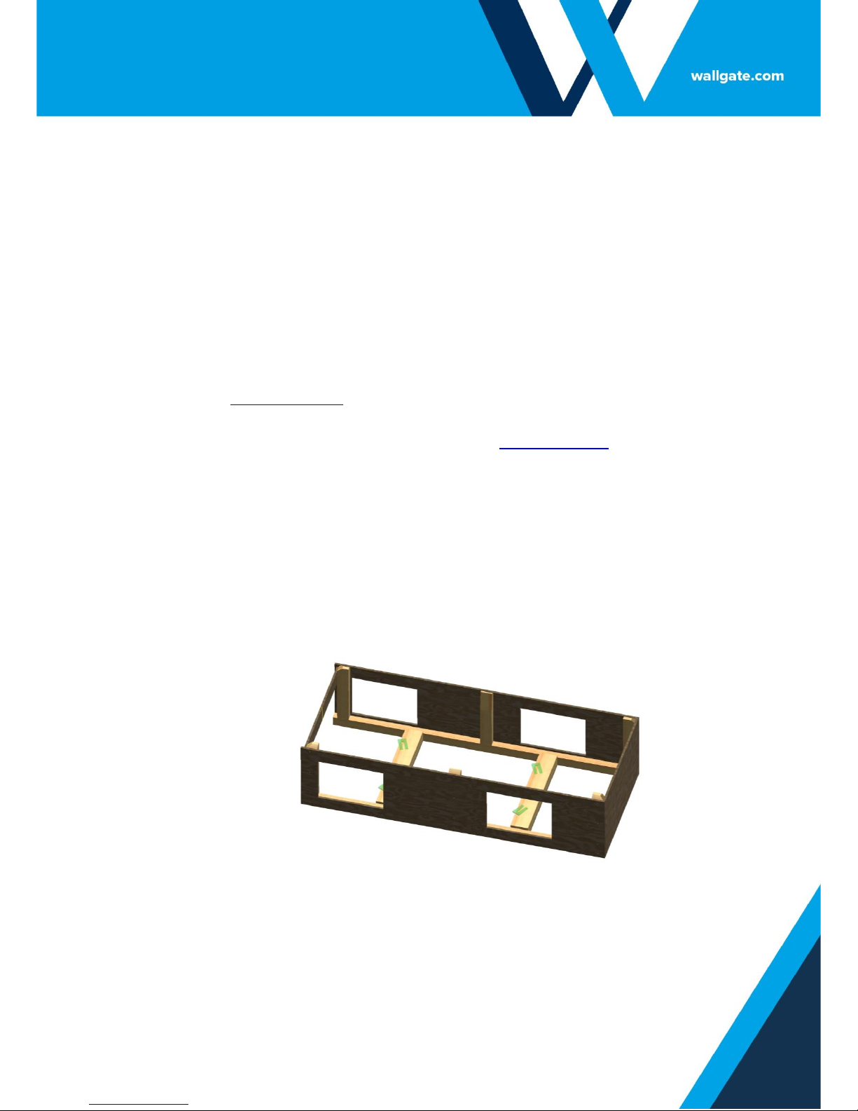
5.2.Site Preparation....................................................................................................7
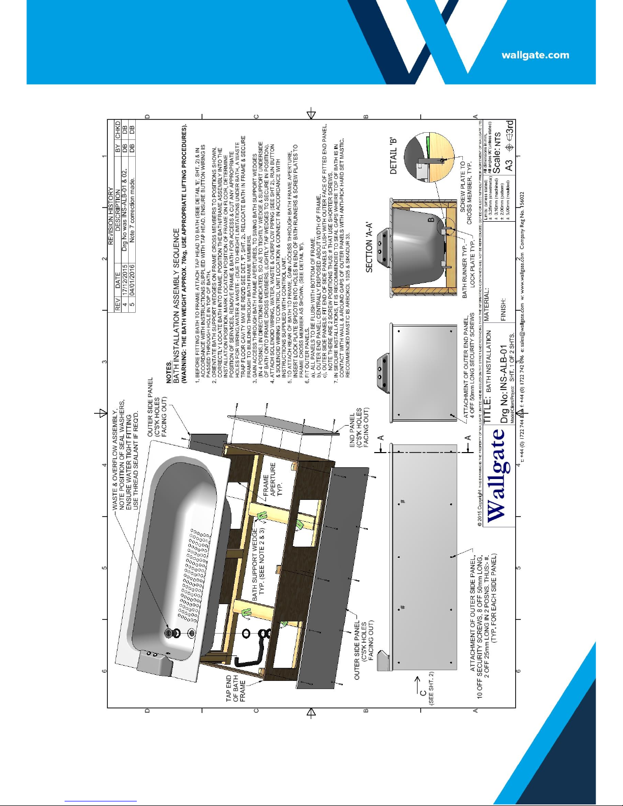
5.2.1. Installation Guidelines........................................................................................8
5.3.Connecting Services to the Bath.........................................................................12
5.4.Fitting the Side Panels........................................................................................15
5.5.Commissioning for use........................................................................................15
5.6.Technical Specifications......................................................................................16
6. User and Maintenance Instructions.......................................................................17
6.1.Operation............................................................................................................17
6.2.Maintenance .......................................................................................................18
7. Related Documentation.........................................................................................18

Revision 3
4
Product Manual ALB-01,03&05
1. Disclaimer
Every effort has been made to supply information within this manual which is correct.
Wallgate Limited will not be liable for any damage or loss that arises if the person
installing, operating or maintaining the unit has not read or not complied with the
manual
In any event, and without prejudice to any warranties in Wallgate Limited’s terms and
conditions of sale, Wallgate Limited’s liability for all damages and losses (including
negligence) shall not in any circumstances exceed the amount paid by the customer
for the unit.
Wallgate reserves the right to alter, update or improve its product specification at any
time without prior notice. This manual is specific to the product that it has been
supplied with at the date of supply.
Without prejudice to any warranties in Wallgate Limited’s terms and conditions of
sale, any warranty will be invalidated if the equipment is installed or serviced by
unqualified personnel.
No part of this publication and the information contained may be reproduced,
transmitted, stored in a retrieval system, used or disclosed wholly or partly without
prior written permission from Wallgate Limited.
For full warranty details please see Wallgate Limited Terms and Conditions.
Please ensure this manual is passed to the end user. The manual forms an integral
part of the product and should be kept for its working life. Additional copies of this
and other supporting documents are available by contacting Wallgate Ltd or by
visiting www.wallgate.com

Revision 3
5
Product Manual ALB-01,03&05
2. Conventions
Certain conventions are used in this manual to make it easier to read and
understand. They are given in the sections below.
2.1. Warning
A warning with white text on a red background is used to give information about
hazards that can cause injury or death. Read and understand these warnings before
you install and commission the bath. Failure to heed these warnings can have serious
consequences.
WARNING! This is a warning!
2.2. Note
A note with black text on a yellow background is used to draw your attention to
important and useful information.
NOTE: This is a note.
2.3. Numbered procedures
Steps in procedures are numbered, starting from 1.
1. This is step 1.
2. This is step 2 etc.
2.4. Bullet lists
•A bullet list is used to give information that is not sequential.
2.5. Menu items
Menu items, submenu items and settings, where available, are given in bold.

Revision 3
6
Product Manual ALB-01,03&05
3. Glossary
The glossary lists all words, abbreviations and technical terminology used in this
manual, along with a short description of these terms.
Term
Description
Anti-Ligature
Recently we have become aware that there is some
inconsistency in the market as to the exact meaning of "anti-
ligature". When we use this phrase about our products it
means that we have designed and tested the product to
reduce any risk of that product being used as a ligature
attachment point.
Piezo electric touch button
A piezo electric touch button converts the force applied to the
face of the touch button into an electrical signal. Piezoelectric
touch buttons are used in the bath tap to operate the hot and
cold-water outlets.
IR Sensor
The infrared (IR) sensor detects infrared radiation from your
hand, this creates an electrical signal. IR sensors used in the
ALB bath operate the hot and cold-water taps. To operate the
sensor switch, hold your hand within 50mm of the sensor.
BSP
The British Standard Pipe (BSP) thread is a family of standard
screw thread types that has been adopted internationally for
interconnecting and sealing pipe ends by mating an external
(male) with an internal (female) thread.¹
‘Y’ Strainer
Accessible inline pipe filter housing for removal of rust, scale
and other pipe debris from water flow by means of perforated
or wire mesh.
¹Description sourced from Wikipedia at http://en.wikipedia.org/wiki/British_standard_pipe_thread
4. Overview
The ALB Bath & tap is a solid surface anti ligature and anti-vandal full size bath tub
with hot and cold water taps that are operated by piezoelectric touch buttons.
The ALB bath can also be operated by IR sensor or pneumatic push button control.
The moulded bath fits into a frame that is available as an option from Wallgate and is
supplied with external panels (bath and panels available in a choice of colour).
The bath is available in three model options to suit installation mounting orientations
with side panels to suit each orientation.
The bath, mounted in a Wallgate frame with side panels when installed in
accordance with these instructions is suitable for use in a secure environment.
For assistance and more information, contact the Wallgate sales service.

Revision 3
7
Product Manual ALB-01,03&05
5. Installation and Commissioning
5.1. Package Contents
Before you begin the installation, make sure that you have the following items:
✓1 off Product manual.
✓1 off ALB Bath tub moulding complete with fitted overflow nozzle.
✓1 off Bath Waste outlet (1½”) with 2 seal washers, clamp nut & overflow
pipe kit.
✓1 off bath waste plug.
✓2 off bath to frame Lock Plates with fixing screws.
✓1 off Bath Tap assembled with 2 off Piezo touch button (1 off red, 1 off
blue).
✓2 off ¾” BSP flanged lock nuts.
✓2 off 22mm x ¾” BSP push fit straight tap connectors.
✓2 off solenoid valves & cables. Supplied with 4 off 22mm x ¾” BSP push fit
connectors.
✓2 off ø22mm x 100mm long copper pipes.
✓1 off Electronic Control Unit model WDC100-1 (or optional WDC200).
✓1 off Bath Installation sheet (to suit relevant side panel set).
✓1 off Bath Frame. (Optional extra, sold separately).
✓1 off Bath panels with fixing screws (Note panels supplied will vary
according to bath model).
oModel ALB-01 includes two side panels & one end panel.
oModel ALB-03 includes one side panel & one end panel.
oModel ALB-05 includes one side panel.
5.2. Site Preparation
WARNING! To maintain the anti-ligature and anti-vandal properties of this
product it must be installed in line with the following points:

Revision 3
8
Product Manual ALB-01,03&05
1. Ensure product fixings are correctly fitted as detailed in the following
instructions.
2. Ensure all fixings are tightened to the recommended torque as detailed in the
following instructions.
3. Seal the edges of the product to the wall and floor. Fill gaps between the bath
panels, the bath and the bath tap using anti-pick hard set mastic, examples of
recommended types are:
a. Arbokol 1025, manufactured by Adshead Ratcliffe & Co Ltd
(www.arbo.co.uk).
b. Sikadur 33 manufactured by SIKA Ltd (www.sika.co.uk)
5.2.1. Installation Guidelines
▪The bath must be attached to a frame (see Fig. 1) mounted on a level floor
suitable for supporting the bath tub, water and occupant. See Table 1 for
the weight. Refer to Figures 2 and 3 for a typical installation of the bath.
▪Hot and cold-water supplies are necessary. See Table 1 for the
specifications of the water supplies.
Figure 1. Wallgate bath support frame
•Using the appropriate Bath Installation site orientation instruction sheet:
ALB-01, ALB-03 or ALB-05.
oDetermine the position of the optional electronic control unit (see
Figure 4), position of services, cut any appropriate holes for water,
waste and wiring.

Revision 3
9
Product Manual ALB-01,03&05
NOTE: Due to space limitations between underside of bath & floor, a floor
cavity or opening for the waste trap may be required, see Figure 3, DETAIL ‘F’.
WARNING! The bath alone weighs approx. 70Kg. Always use safe lifting
procedures when lifting heavy loads. Make sure the bath is correctly supported
and located to frame and wall.
NOTE: Make sure you do not abrade or damage the cables, water & waste
pipes when mounting the bath into position or when inserting them through
the walls etc.

Revision 3
10
Product Manual ALB-01,03&05
Figure 2. Typical Bath Installation (sht. 1)

Revision 3
11
Product Manual ALB-01,03&05
Figure 3. Typical Bath Installation (sht. 2)

Revision 3
12
Product Manual ALB-01,03&05
5.3. Connecting Services to the Bath
Follow the instructions to connect services to the bath:
NOTE: Flush the water supply pipes to remove any debris and trapped air.
NOTE: Fit a Y strainer or similar in the feed pipes before connection to the
solenoids, especially on installations where loose particles from older pipe
work can cause a blockage in the valves & taps.
NOTE: Fit a service isolating tap on the feed to each solenoid. This allows easy
maintenance when required. The isolating tap is not supplied by Wallgate.
NOTE: Pipe sealing compound should be avoided. If it is used, it should be
used sparingly. To prevent blockages and damage to the bath tap aerators and
water solenoid valves.
1. Tap Head: On the pre-installed bath mounted tap head, fit the two push fit
22mm x ¾” BSP straight push fit connectors onto the protruding ¾” BSP water
inlets. Then tighten nuts to 4Nm.
2. Bath waste:
a. Fit the supplied seal washer under the chrome rim of bath waste. Insert
the bath waste spigot through the bath outlet hole from the top inside of
bath.
NOTE: If required to ensure a water tight bath waste fitting use a suitable
sealant.
b. Install the 2nd seal washer onto the protruding bath waste spigot.
Orientate and fit the overflow housing open face against 2nd seal
washer. Fit nut onto spigot and tighten. Push the top end of overflow
pipe onto protruding pre-fitted bath overflow spigot.
3. Solenoid Valve:
a. On the valve, note direction of water flow and keeping the solenoid
valves in a horizontal & coil upright orientation, with 22mm x ¾” push fit
connectors fitted and tightened to 4 Nm. Push fit 22mm hot and cold
pipes from solenoid to tap head.

Revision 3
13
Product Manual ALB-01,03&05
NOTE: Ensure when cutting copper pipes to fit into push fit connectors the
tube is cut with a suitable rotary pipe cutter, to ensure it is burr free and the
tube end is slightly chamfered to avoid damage to the rubber seal on the push
fit connectors.
b. Fully insert hot and cold-water supply feeds to solenoid valve inlet push
fit connectors.
4. Bath Waste, cont’d: Connect bath waste pipe (1½”) to bottom of bath waste
spigot via a suitable waste trap equivalent to 50mm minimum seal. Due to
limited space below the bath, a floor cavity or opening for the trap may be
required (see Fig. 3).
5. Control Unit:
a. An electrical supply of 230V 50Hz with a 2 Amp rating is required for
the electronic control unit.
NOTE: The position of the Control Unit is important to provide access should
adjustments be necessary and for maintenance. It must be located in a dry
area & away from plumbing that could potentially leak.
b. Installation of the electronic Control Unit must be completed prior to
proceeding to:
i. Plug the piezo touch button cables into the electronic control unit
input sockets. Refer to the product manual of the control unit to
identify the correct input sockets before you make the
connections.
ii. Plug the water solenoid valve cables into the electronic control
unit input sockets. Refer to the product manual of the control unit
to identify the correct input sockets before you make the
connections.

Revision 3
14
Product Manual ALB-01,03&05
Figure 4, Solenoid & Control unit installation & connection.

Revision 3
15
Product Manual ALB-01,03&05
5.4. Fitting the Side Panels
•The bath panels provided vary according to the bath model.
•The long side panels are designed to be retrofit for either side of the bath.
•End panels will vary in length according to the bath model, an end panel for
a bath fitted with side panels on both sides will be shorter in length than
one for a bath with just one side panel.
•Security screws are provided for fitting the panels; the screws require a
T27-H TORX bit driver.
•Ensure all panels are fitted aligned to the bath and frame and gaps are
avoided.
NOTE: For maximum security an anti-pick hard set mastic must be applied
around the panels to fill any gaps, and between the panels and the bath rim
and the walls. Refer to section 5.2 for details on suitable anti pick products.
5.5. Commissioning for use
To commission the ALB bath:
1. Fully open the water supply isolating taps. Check the system for leaks.
2. Operate the hot and cold water by pressing the piezo touch buttons.
Operate the water on both hot & cold several times to make sure all air has
been purged from the system and to ensure that the flow rate is correct.
3. If a thermostatic mixer valve (TMV3) (Not supplied by Wallgate Ltd) is fitted
to the plumbing system for the hot outlet, you may have to adjust the valve
to set the correct hot water temperature. If so, you should do so in
accordance with the instructions supplied by manufacturer of the

Revision 3
16
Product Manual ALB-01,03&05
5.6. Technical Specifications
Bath only, Weight
70 Kg
Dimensions, ±3mm
1696mm (L) x 499mm (H) x 748mm (W)
Water Supply
Minimum operating pressure 0.5 Bar (See note 1 below)
Minimum recommended dynamic pressure 1 Bar (See note 2)
Maximum rating 10 Bar
Flow rate 30 LPM
Supply pipe size 22mm copper
Waste connection
40mm (1½” pipe)
Bath water volumes:
1. Volume to
overflow.
2. Volume when
water depth in
bath is 153mm.
148 litres
85 litres
Optional Control Unit Specifications
Power supply
230V AC 50/60Hz 2 Amp single phase
USA / CANADA:
120V AC 2Amp, 60Hz for models WDCA100 and
WDCA200.
Power rating
Maximum power rating 60 W
Weight
1.0 Kg
Dimensions
200mm (W) x 150mm (H) x 80mm (D)
Enclosure IP Rating
IP53
Regulatory
compliance
Complies with RoHS, LVD 2014/35/EU and EMC
2014/30/EU directives.
Table 1. Technical specifications
NOTE: The minimum operating pressure quoted is the minimum that the water
solenoid valves will operate at. At this minimum pressure the flow will be no
greater than 6 litres per minute & could potentially be a lot less depending
upon the size of feed pipes and type of water feed whether mains fed, or
gravity system fed.
NOTE: The recommended minimum dynamic pressure of 1 Bar will deliver a
flow rate of 12 LPM with a suitably sized water feed pipe (min 22mm) and
supply.

Revision 3
17
Product Manual ALB-01,03&05
6. User and Maintenance Instructions
The ALB Bath, Support Frame with Panels, Tap Head and Control Unit are designed
and manufactured from high quality materials. If you install, operate and maintain
them according to the instructions given in this manual, the unit will give reliable,
efficient service. If you need any further information or advice, please contact
Wallgate customer services.
Wallgate offers a comprehensive service package, details of which can be obtained
from our customer service department. A spare parts service is also available.
Any service or repair work must be done by a qualified engineer. During the warranty
period, the service or repair must only be done by a Wallgate engineer or appointed
service agent. Refer to the Wallgate terms and conditions for warranty information.
6.1. Operation
1. The unit is switched ON and OFF using the main isolation switch (provided by
the installer), located near to the electronic Control unit.
NOTE: If a fault occurs with the unit you must set the isolator to the OFF
position until the fault is repaired by a qualified engineer.
WARNING! Risk of electric shock, serious injury and death. Only trained and
qualified personnel should remove the cover of the electronic control box.
2. Operate the cold and hot water nozzles by pressing the piezo touch buttons.
The piezo touch buttons do not have any moving parts. Operate the switch by lightly
pressing the button face with your finger tip. One press of either button, hot or cold,
will allow that water cycle to run for a set time of 180 seconds and then stop. During
a water cycle the water flow can be stopped, by pressing the respective button again.
A new water cycle can be activated once the previous water cycle has been
interrupted or has stopped.
If the cycle time of 180 seconds needs to be changed, detailed information on
settings for adjusting cycle times, limiting the number of cycles, timed lockouts etc.,
refer to Control unit product manual supplied.
The Control unit cannot control temperature of the hot water, this is usually controlled
by a thermostatic mixer valve.
For more information, contact the Wallgate after sales service.

Revision 3
18
Product Manual ALB-01,03&05
6.2. Maintenance
General wear mainly affects the components in contact with water. If the unit is
installed in a hard water area, lime scale removers must be used on the bath and
water nozzle components.
The water aerator nozzle can be dismantled using a special key and the inserts can
either be replaced or immersed in a lime scale remover solution for cleaning. Details
of the key and components are given in the spares list table below.
Part Number
Description.
WN4003
Water nozzle aerator insert
RW9602
Rubber seal for WN4003
WF4002
Locking ring for WN4003
DL7523
Key to remove Tap head aerator nozzle ring (FLAT TYPE KEY)
DL7539
Key to remove Tap head aerator nozzle ring (CIRCULAR TYPE
KEY)
Table 2 Spare Parts List
7. Related Documentation
The ALB bath can be used with any of the following control units:
•WDC100. For more information on this control unit, refer to the WDC100
product manual.
•WDC200. For more information on this control unit, refer to the WDC200
product manual.
•INS-ALB-01 Bath Installation drawing.
•INS-ALB-03 Bath Installation drawing.
•INS-ALB-05 Bath Installation drawing.

Revision 3
19
Product Manual ALB-01,03&05
Notes:
PAGE INTENTIONALLY LEFT BLANK

Revision 3
2
Wallgate Ltd.
Crow Lane, Wilton,
Salisbury, Wiltshire,
SP2 0HB, England
tel: +44 (0) 1722 744594
fax: +44 (0) 1722 742096
email: service@wallgate.com
web: www.wallgate.com
Other manuals for ALB-01
1
This manual suits for next models
2
Table of contents
Other Wallgate Bathtub manuals
Popular Bathtub manuals by other brands

Toto
Toto PAY1570D Installation instructions & user guide

American Standard
American Standard Savona Corner Whirlpool 2902.028WC Specification sheet

Senior Bad
Senior Bad W23 Assembly instructions

Jetta
Jetta Classic Series Owner's manual & installation guide

Kohler
Kohler Iron Works Tellieur K-727 installation guide

Clou
Clou First CL/05.13010.20 installation instructions