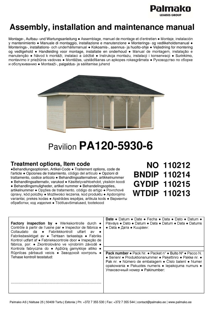
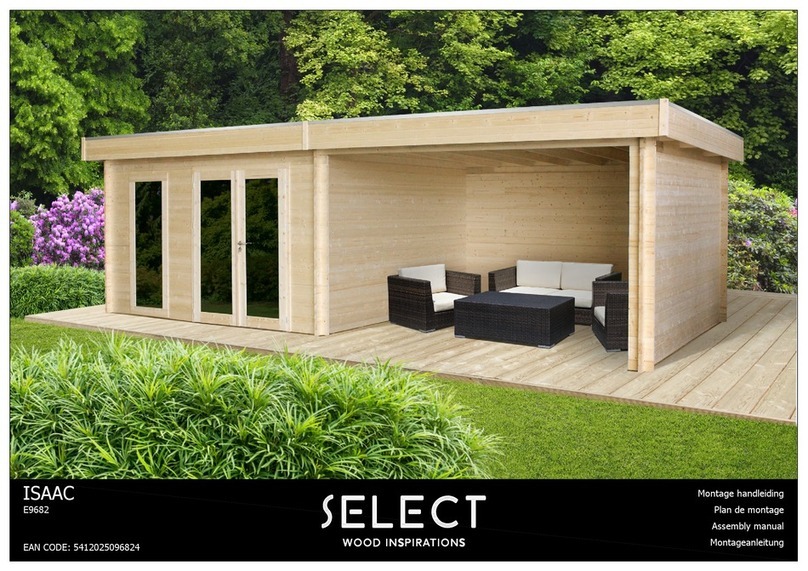
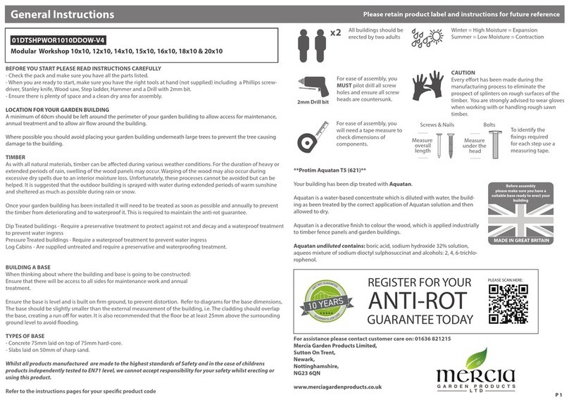
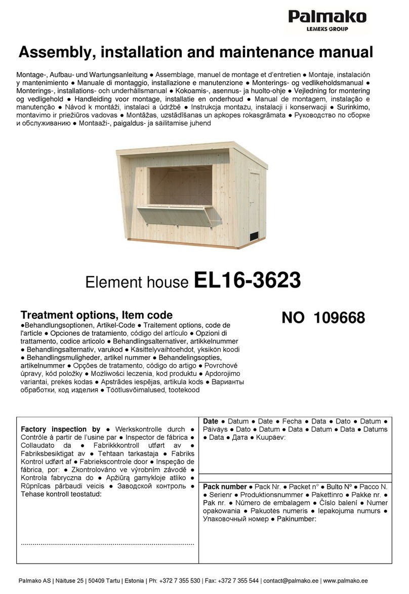
Walton 7x7 Corner shed User manual

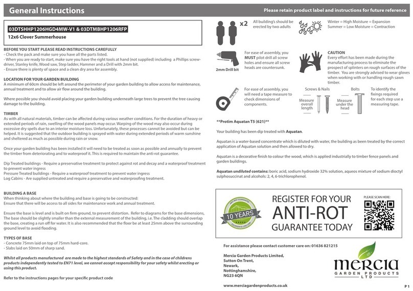
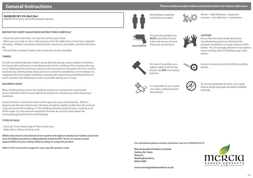
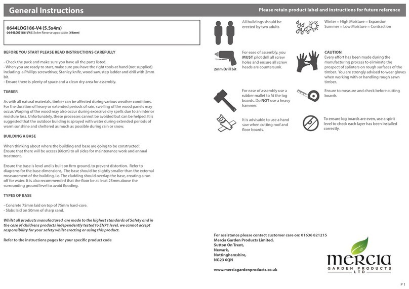
This building should be
erected by two people.
For ease of assembly, it is
advisable to pilot drill all
screw holes and ensure all
screw heads are countersunk.
WINTER = HIGH MOISTURE = EXPANSION
SUMMER = LOW MOISTURE = CONTRACTION
Drill
2mm bit
x2
NATURAL MOVEMENT OF TIMBER THROUGHOUT THE SEASON
Timber is a natural material and will, during the year pick up moisture in damp periods and dry out during hot spells. There will be constant expansion
and contraction of the timbers which will be particularly noticeable during the dry periods as the boards will shrink, this is why all buildings have
slight tolerances built into them.
BUILDING A BASE
When thinking about where the building and base is going to be constructed: Ensure that there will be access to all sides for maintenance work and
annual treatment.
TYPES OF BASE
- Concrete 75mm laid on top of 75mm hard-core.
- Slabs laid on 50mm of sharp sand.
PLEASE READ INSTRUCTIONS CAREFULLY.
For domestic and family use only
Retain Instructions for future reference
Before you start...
All buildings including the underside of the floor must be treated with a good quality waterproof
preservative or treatment prior to or during assembly, and retreated annually.
Preservative/treatments are available in a choice of colours and is left to the customers preference.
For Assistance Please Contact Customer Care on 0800 0142 333
Whilst all products manufactured at Walton Garden Buildings Limited are made to the highest standards of Safety and in the case of
childrens products independently tested to EN71 level,Walton Garden Buildings Limited cannot accept responsibility for your safety whilst
erecting or using this product.
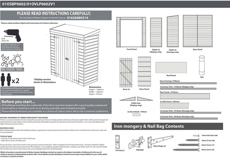
Dimensions
Depth = 2223mm
Width = 2802mm
Height = 1984mm
1x Front Fascia- 60 x 1213mm
2x Side Fascia- 60 x 1202mm
2x Rear Fascia- 60 x 2050mm
Fascia
2x Front Cover Trim- 45 x1900mm
2x Side Cover Trim- 30 x1900mm
1x Door Strip- 45 x 1680mm
1x Door Strip- 60 x 1680mm
Strip
Door Panel Window Panel Plain Panel
Rear Panel Right Rear Panel Left
Floor Roof
3x Roof Support block- 45 x 210mm
Framing
1x Rear roof framing- 32 x 2018mm
1x Rear roof framing- 32 x 2049mm
1x Front roof framing- 32 x 1196mm
2x Side roof framing- 32 x 1149mm
2x Door block- 32 x 140mm
1x Rear Panel Framing- 32 x 1806mm
1x Large Roof Support bar- 70 x 2650mm
1x Back Roof Support bar- 70 x 1303mm
1x Front Roof Support bar- 70 x 748mm

3x Turn Key
5x L’ Bracket
4x Tee Hinge
Remove transportation blocks
from the bottom of each panel
before beginning assembly.
Each Panel should have two
blocks.
Place floor on a firm and level
base, ensure base has suitable
drainage free from areas
where standing water can
collect. (see front page on
base requirements).
Step 1
Do not secure the building
to the floor until the roof is
fitted. Fix the panels onto
the floor using 50mm
screws in alignment with
the floor joists
Fix the corner with 3x
50mm screw a shown in
diagram.
Step 2
Place right back panel
against floor panel.
Fix the Rear Panel Framing
to the side as shown in
diagram, using 3x 50mm
screws.
3x50mm screws
Step 3
11x50mm screws
Step 4
Fix Plain panel and Window
panel using same method
shown in step 3.
10x50mm screws
30mm Black Screw 3
30mm Screw 80
50mm Screw 30
100mm Screw 8
40mm screws 78
Felt Tacks 80
60mm Screw 10

Step 5
Before erecting the door panel
it is recommended to fit both
doors using the 2x T hinge per
door.
Fix hinges to the doors with
30mm screws ensuring the
screws are located into the door
framing.
Position each door on to the
building leaving enough gap in
between doors and building. Fix
the door to the building with
30mm screws.
Fix door block and turn key to
top and bottom rear of right
door , using 40mm screws and
black 30mm screw for the turn
key.
fix the following strips to the
front of the doors using 3x
40mm screws per strip into the
rear framing
45 x1600mm to the left door
60 x 1600mm to the right door
Then attach the remaining turn
key to the left door using 1x
30mm black screw in line with
the back framing.
28x30mm screws
6x40mm screws
3x30mm black screws
Step 6
Erect the door panel into
positon and fix to each panel
using 6 x 60mm screws as
shown in method c
Use 2 x 50mm screws to fix
panell to floor.
6 x60mm screws
2x50mm screws
c
c
c
c
c
c
c
Step 7
30mm
screws
First position the Large Roof
support bar in the centre of the
building between the left and
right corner. Ensure the top face
of the support is level with the
top of the building and then
mark position below the
framing for the fittings.
Using the marked position, align
the roof support block and fix
using 2x100mm screws
diagonaly through the block. Do
this on both sides.
4x100mm screws
2x100mm screws
Roof support must be
level with top of framing

First position the Front Roof
support bar in the centre of
the building between the front
of the building and the large
roof support bar. Ensure the top
face of the support is level with
the top of the building and
then fix using L’brackets.
Position the Back Roof
support bar in the centre of
the building between the back
and the large roof support bar.
Ensure the top face of the
support is level with the top of
the building and then mark
position below the framing for
the fittings.
Using the marked position,
align the roof support block
and fix using 2x100mm screws
diagonaly through the block.
At the front, secure the support
bar into position using L’
Brackets.
Step 8
4x30mm screws
4x30mm screws
20x30mm screws
2x100mm screws
2x100mm screws
Roof support must be
level with top of framing
Step 9
Layout the roof sheet and
position the roof framing onto
the sheet, as shown in diagram.
Ensure framing is level around
the edges and fix each piece
using 40mm screws
Rear roof framing
Rear roof framing
Side roof framing
Side roof framing
Front roof framing
17x40mm screws
1
2
3
50mm
50mm
50mm
3020mm
1000mm
1420mm
50mm
Cut three strips from roll of felt,
2x3020mm and 1x1420mm in
length. Place felt on top of roof
sheet and align as shown in
diagram ensuring strip 3 over
hangs the front by 50mm. with
equal spacing at each corner.
Ensure strip 1 is the first piece
placed down then lay sheet 2 and
then 3 on top. make sure each
sheet overlaps the next creating a
run off.
Use a fascia as a guide to mark out
the angled cuts including 50mm
overhang.
Cut the sides as shown in diagram
at the dotted lines, use fascia
width as guide for overhang. Cut
Triangle with 50mm overhang
again using fascia as a guide.
Fix roof to building as shown in
step 7, then place sheets back into
position in diagram with 50mm
over hang all around. fix each
sheet using felt tacks along where
sheet overlap.
Step 10
Place the roof section on top of
builidng, ensure roof framing
slots over each side.
Fix the roof sheet into position
using 40mm screws ensuring
that they line up with the
vertical framing inside the
building and along the length
of the internal roof support
bar.
*It is recommended
to cut the felt sheets
before fixing the roof
to building.
21x40mm screws
Step 11
80x10mm felt tacks

Step 12
Fix the cover trims as shown
using 3x 40mm screws per
strip.
45 x 1900mm
30 x 1900mm
Fit the fascias to the
building over the felt
and secure in place with
40mm screws as shown.
Pre drill to avoid
splitting.
12x40mm screws
Step 13
17x40mm screws
Other Walton Garden House manuals
Popular Garden House manuals by other brands
Palmako
Palmako Veronica 4 installation manual

Palmako
Palmako Helena installation manual

Yardline
Yardline WESTMONT GABLE 12' x 16' manual

Vikträ
Vikträ LAKER SHED 40 manual

Lemeks
Lemeks Palmako FR44-6030-1 Assembly, installation and maintenance manual
Palmako
Palmako EL16-2132 Assembly, installation and maintenance manual
OLT
OLT SunShed Garden Shed SSGS1212-AK-METAL Assembly manual

Décor et Jardin
Décor et Jardin 68655S000 Assembly Notice

G21
G21 GRAH 915 manual

Grosfillex
Grosfillex ABRI DECO H20A Assembly instructions

STILLA
STILLA Master Assembly instructions

Mercia Garden Products
Mercia Garden Products 01DTOVAX1006DDFW-V1 manual