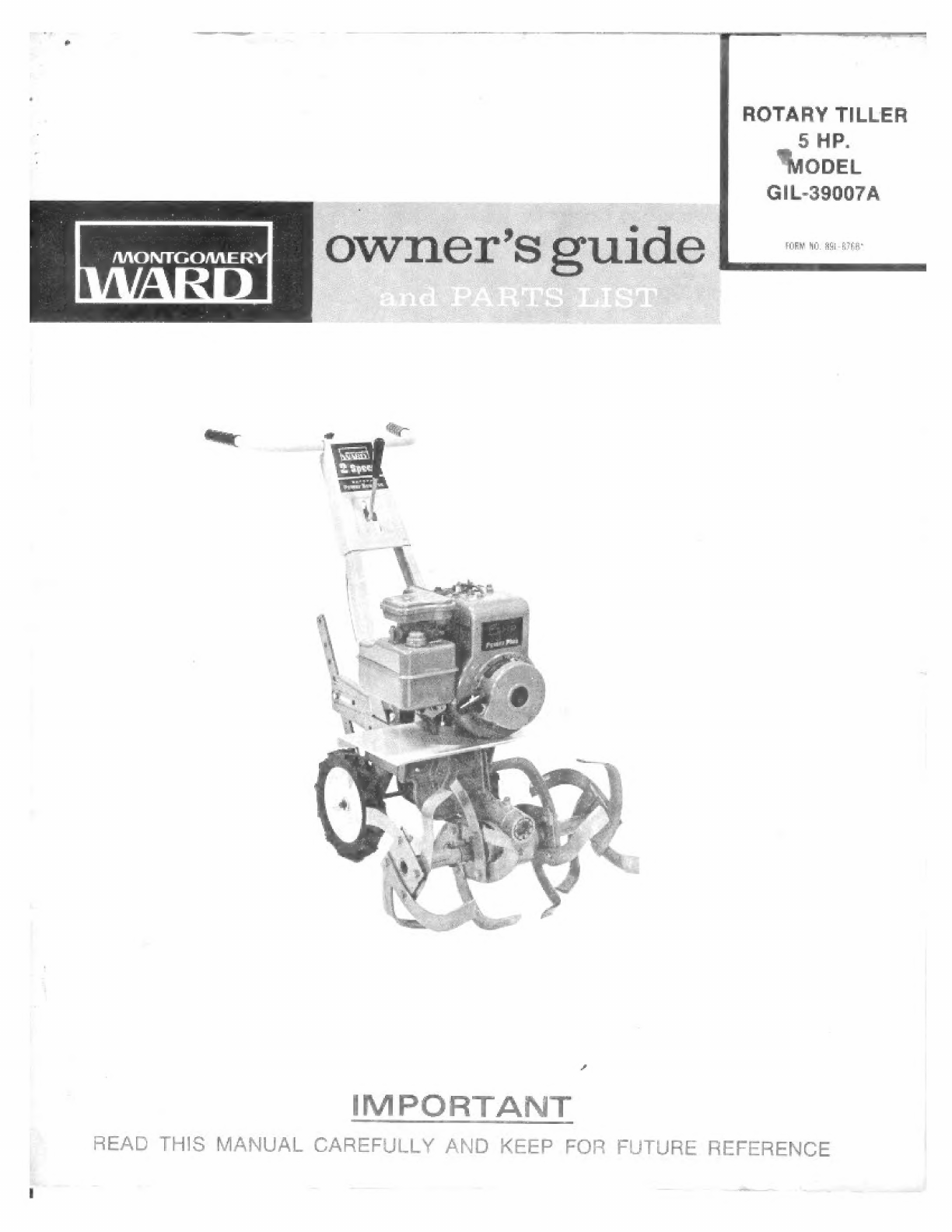
Ward GIL-39007A User manual

|
ROTARY
TILLER
5
HP.
ODEL
GIL-39007A
IMPORTANT
READ
THIS
MANUAL
CAREFULLY
AND
KEEP
FOR
FUTURE
REFERENCE

CONTENTS
Hardware
Bag
Contents
l
A
kul
3
General
Introduction
Safety
Tips
.___
ba
sabi
E
4
Preparation
for
Operation
5-8
Initial
Servicing
MAMO
8
Controls
and
Operation
|
|
9-10
Starting
Your
Rotary
Tiller
10
Versatile
Tine
Combinations
see
ч
11
Adjustment
and
Servicing
11-12
Lubrication
and
Maintenance
13
Storage
ee
|
алаа
713
Tier
РАЛЕ...
tee
Жеб...
14
Tiller
Parts
ШЕ.
аа
ester
VO
Gear Case
Parts
and
Parts
List
ОРИ
ЕЕ
оно.
|.
How
to
Order
Replacement
Parts
—
|
20
Fri
MPORTANTI,
Баи
Но
caama
if
ħa
fissa
of
Coin
—
й
a
The
ra
on
ta
ser
ш
bii
ac
pee
€.
d
Greeting
ube
OF
Тый
LAS
GF
Тый
ТАТЕ
GF
CL,
Cee
eee
ee
ews
saħħaħna
3
i
|
4
à
IMPORTANTI
Rècord
tha
unit
model
number
and
its
serial
number
on
the
back
page
of
this
manual
for
tuture
reference
when
ordering
гераяг
parts
of
identifiċaliċri
if
unit
Рё
les!
or
stolen
The
manufacturar
reserves
the
right
ta
make
changes
on
and
to
ваа
improvements
upon
its
products
at
any
time
without
notice
or
obligation,
The
manufacturer
also
tegerves
the
night
ta
discontinue
manulacture
of
any
product
at
its
discretion
al
any
time.

HARDWARE
BAG
CONTENTS
The
items
illustrated
below
are
used
during
the
assembly
of
your
Tiller.
They
are
drawn
actual
size
and
can
be
helpful
in
determining
the
correct
hardware
needed
in
each
assembly
step.
HEX.
HD.
CAP
SCREW
4-16
x1"
HEX.
HD.
САР
SCREW
CLEVIS
PIN
%-24
x
134
Heat
Treated
CLEVIS
PIN
(б
==,
STOP
COLLAR
“Long”
"апе
РІМ
|
xi
Lali
SQ. HD.
SET
SCREW
C,
Va
-2
HEX.
NUT
ези
СОТТЕА
РІМ
HEX.
NUT
38-16
3/32
х
34
34-24
“Coarse Thread”
"Fine
Thread”
се
CONTROL
KNOB
=
LOG
RUBBER
=н
MA
(IS.
PIVOT
EU
NG
SPRING
CLIP
|
FLAT
WASHER
ENGINE
Зв
S.A.E.
SHIM

GENERAL
INTRODUCTION
This
Owners
Guide
has
been
especially
prepared
to
provide
the
information
needed
to
assemble
and
op-
erate
your
tiller
with
greater
satisfaction.
Read
this
Owners
Guide
and
the
engine
instructions
carefully.
Be
sure
you
know
what
the
controls
are
for
and
how
they
operate.
The
care
your
tiller
requires
is
small,
but
important.
Keep
it
clean
and
well
lubricated.
With
proper
care
and
operation,
as
explained
in
this
manual,
you
АШ
obtain
long
and
efficient
service,
Information
regarding
operation
and
maintenance
of
the
engine
is
not
included
in
this
manual.
A
separate
instruction
manual
is
included
with
your
tiller
and
should
be
consulted
for
all
information
concerning
engine
adjustments
and
operation.
|
SAFETY
TIPS
Don't
Forget
that
SAFETY
starts
with
you!
Your
rotary
tiller
was
built
to
the
highest
standards
in
the
industry.
However,
a
rotary
tiller
is
only
as
safe
as
the
operator.
As
with
any
type
of
power
equip-
ment,
carelessness
or
error
on
the
part
of
the
operator
can
result
in
injury.
Please
read
and
follow
these
instructions
on
safe
operation
and
be
certain
anyone
using
this
rotary
tiller
is
familiar
with
these
simple
rules:
è
Improper
use
of
the
rotary
tiller
can
result
in
in-
jury.
Give
complete
and
undivided
attention
to
the
work
you
are
doing.
®
Know
the
controls
and
how
they
operate.
è
Know
how
to
stop
the
rotary
tiller
and
engine
in-
stantiv.
Disenguge
power
and
stop
engine
before
cleaning,
removing
obstacles.
or
making
adjustment,
Keep
children
and
pets
a
safe
distance
away
from
rotary
tiller.
Do
not
allow
anyone
to
operate
rotary
tiller
with-
Out
proper
instruction
and
supervision.
Exercise
caution
to
avoid
falling.
Don't
start
the
engine
and
tines
until
you
are
ready
to
start
tilling.
Stop
the
engine
whenever
you
leave
the
machine.
Disengage
clutch
before
starting
engine.
Keep
hands,
feet
and
clothing
away
from
power-driven
parts.
Keep
rotary
tiller
in
good
operating
condition
and
keep
safety
devices
in
place.
Store
gasoline
in
a
safe
container.
Store
the
con-
tainer
in
a
cool,
dry
place.
Not
in
the
house
or
near
heating
appliances.
Open
doors
if
engine
15
run
in
garage.
Exhaust
gases
are
dangerous,
Fill
gas
tank
outdoors.
Avoid
spilling
gasoline.
Don't
fill
tank
while
engine
is
running
or
while
you
are
smoking.
The
replacement
of
any
part
on
this
product
by
other
than
the
manufacturer's
authorized
replacement
part
may
adversely
affect
the
performance,
durability
or
safety
of
this
product.

PREPARATION
FOR
OPERATION
This
tiller
is
shipped
in
one
carton
completely
assembled
except
for the
handle,
control
rod,
tailpiece,
depth
con-
trol
and
outer
tine
hub
assemblies.
A
hardware
bag
is
also
furnished
which
contains
all
the
extra
parts
and
hardware
needed
to
assemble
the
tiller
correctly.
Note:
page
3
illustrates
the
hardware
bag
contents.
Use
this
page
for
correct
identification
of
hardware
items
used
during
assembiv.
CUSTOMER
NOTICEI
The
engine
on
this
tiller
was
shipped
WITHOUT
oil
in
the
crankcase.
See
engine
instructions
for
proper
type
oil
and
crank-
case
capacity.
IMPORTANT!
AN
items
marked
with
an
asterisk
(*)
can
be
found
in
the
hardware
bag.
1.
Remove
tiller
and
all
other
parts
from
the
shipping
carton.
2.
Attach
the
handle
to
the
handle
brackets,
Fig.
1.
Position
handle
over
brackets
and
secure,
using
four
(4):
34-16
x
1”
hex.
hd.
cap
screws*,
36
lock
washers*
and
is-16
hex.
nuts'.
3.
Attach
the
tailpiece
to
the
rear
of
main
frame,
Fig.
2.
Remove
tiller
belt
guard,
Loosen,
do
not
remove
the
thumb
screws.
Pull
spring
clip
from
the
tailpiece
hanger
pin
and
remove
hanger
pin.
Place
tailpiece
into
opening
in
rear
of
main
frame.
Line
up
holes
and
replace
the
hanger
pin
as
shown
in
Fig.
2.
Secure
with
the
spring
clip.
4.
Attach
the
depth
control
to
the
tailpiece,
Fig.
3.
Slide
depth
control
into
slot
in
rear
of
tailpiece
and
secure,
using
the
“short”
clevis
pin'
and
spring
clip’.
NOTE!
Refer
to
the
“CONTROLS
AND
OPERA-
TION”
section
for the
hole
position
to
set
the
depth
control
in
depending
on
the
soil
conditions
and
tiller
speed
desired.
The
bottom
hole,
Fig.
14,
is
used
for
transporting
the
tiller
only.
*This
item
сап
be
found
in
the
hardware
bag.
“COARSE
THREAD"
_-~
HANDLE
ral
Is-16
НЕХ.
NUT
%
LOCK
WASHER
—\
UN
д
ы
a-16x
1"
he.
HEX
HD.
—-
CAP
SCREW
FIG.
1
BELT
GUARD
-
TAILPIECE
-
HANGER
PIN
_
т
х
SPRING
CLIP
——
8
Fa
l
off
PALIT
>
i i
‚ш
БУ
Ie
ir,
ИН
ИГ
\
“я
ТАШ
РЕСЕ
б
FIG.
2
SPRING
ү?
L
1
se
У
е
)
CLEVIS
—
Wil?
/
PIN
БЫ
о?
"шл.

THROTTLE
CONTROL
5.
Attach
the
throttle
control
to
the
back
side
of
han-
dle,
Fig.
4.
4
LOCK
WASHER
is-24
HEX.
NUT
Slide
the
threaded
part of
control
into
slot
on
the
back
of
handle.
Slide
the
58
lock
washer
and
36-24
hex.
nut
up
the
control
cable
and
secure
control
to
handle
by
tightening
the
hex.
nut
to
the
control
from
underside
of
the
slot.
CONTROL
CABLE
6.
Reposition
the
outer
tine
hub
assemblies
to
the
proper
end
of
tine
shaft,
Fig.
5.
Note:
For
ship-
ping
purposes,
this
tiller
was
shipped
with
the
outer
tine
hub
assemblies
on
the
opposite
end
of
the
shaft.
Slide
each
outer
tine
hub
assembly
from
tine
shaft
N
me
Ea
Е
.
TINE
ЗНАЕТ“.
L
and
install
ошо
the
opposite
end
of
tine
shaft.
Be
—
sure
the
tilling
edges
(tapered
edges)
are
facing
the
same
forward
direction
as
the
inner
tine
hub
assem-
J
?
3-24
х
124
blies.
HEX.
HD.
HEAT
TREATED
CAP
SCREW
W
LOCK
WASHER
When
the
hole
in
the
hub
assembly
lines
up
with
OUTER
TINE
HUB
'
in-24
НЕХ,
NUT
the
hole
in
the
tine
shaft,
insert
a
is-34
x
134
hex.
ASSEMBLY
“FINE
THREAD"
hd.
heat
treated
cap
screw*
and
secure
with
a
+6
lock
washer'
and
36-24
hex.
nut'
(“fine
thread”).
FIG.
5
Assemble
the
other
outer
tine
hub
assembly
follow-
ing
the
same
instructions
as
outlined
above.
af
ja
7.
“ш
the
control
lever
assembly
to
the
handle,
А
08
56
Р,
AEC
"LONG"
CLEVIS
PIN
er
RUBBER
SPACER.
aid,
Secure
the
(2)
rubber
spacers*,
(2)
Зв
S.A.E.
flat
W
BABE.
l
Co.
:
\
Washers*
and
the
control
lever”
to
the
bracket
on
FLAT
WASHER
yl
|
\
к
1
the
backside
of
handle,
as
shown
in
Fig.
6,
using
CONTROL
LEVER
~
RUBBER
SPACER
lane!
sħana:
mnt
a:
14
34
int
ASSEMBLY
|
Г
a
the
“long”
clevis
pinë
and
a
ba
x
34
cotter
ріп“.
%
S.A.E.
FLAT
WASHER
*This
item
can
be
found
in
the
hardware
bag.
FIG.
6

CLUTCH
CONTROL
LEVER
$.
Turn
the
control
knob*
onto
the the
clutch
control
lever,
Fig.
7.
9.
Attach
the
control
rod
to
the
bell
crank
and
control
lever,
Figs.
$,
9
and
10.
A.
Insert
the
pivot
bushing”
into
hole
in
bell
crank,
Fig.
8.
FIG.
7
CONTROL
ROD
-
B.
Slide
the
straight
end
of
the
control
rod
through
the
hole
in
pivot
bushing,
Fig.
8.
PIVOT
BUSHING
C.
Insert
the
hooked
end
of
control
rod
through
the
hole
provided
in
the
control
lever
on
the
back-
side
of
handle,
Fig.
9,
and
secure
in
place
with
а
as
x
44
cotter
pin”,
STOP
COLLAR
WITH
Va-28x%
4
SQ.
HD.
SET
SCREW
D.
Turn
the
"4-28
x
44
sq.
hd.
set
screw*,
Fig.
$,
into
the
hole
in
the
stop
collar'.
Do
not
tighten
Fic.
8
set
screw.
lee
al
3/sa
х
34
COTTER
PIN
E.
Slide
stop
collar
up
the
control
rod
(from
the
bottom)
towards
the
pivot
bushing.
Go
on
to
adjustment,
next
page.
*This
item
can
be
found
in
the
hardware
bag.
CONTROL
ROD
FIG.
8

TO
ADJUST:
~
ji
Е"
A.
Move
the
clutch
control
lever
to
the
forward
position,
CONTROL
ROD
-
4
|
|
г l
MA
fi
ч.
B.
Move
the
stop
collar
to
within
147
of
the
pivot
bl
)
je
bushing,
Fig.
10,
and
tighten
the
set
screw.
ĠA)
6
ы.
ka
i
Н
ў
м
Б
|
То
check
adjustment:
Place
the
clutch
control
lever
ы
т
in
the
neutral
position,
Turn
the
engine
over
“ы.
үтү]
pr"
slowly
sure
the
belts
slip
on
all
pulleys.
ji
a
slowly
to
be
sure
p
pulle,
E
eee
aaa
TEA
Be
sure
the
spark
plug
wire
has
been
discon-
nected
to
prevent
accidental
starting.
If
tiller
moves
forward
in
the
neutral
position,
loosen
set
screw
and
move
stop
collar
up
slight-
ly.
If
tiller
moves
backward
in
the
neutral
posi-
tion,
loosen
set
screw
and
move
stop
collar
down
slightly.
Retighten
set
screw
after
adjustment
1s
completed.
After
satisfactory
adjustment
has
been
obtained,
reconnect
the
spark
plug
wire.
10.
Slide
handle
grips*
onto
the
handle,
Fig.
11.
If
grips
will
not
slip
on
completely,
tap
end
of
grip
with
a
block
of
wood
and
hammer
until
grip
is
all
the
way
оп.
"ч
ө.
STOP
COLLAR
=
14-28
х
14
50.
HD.
SET
SCREW
FIG.
10
—
=
M
Б
snini
A
*This
item
can
be
found
in
the
hardware
bag.
FIG.
11
~
INITIAL
SERVICING
sia
|.
Before
starting,
see
engine
instructions.
Be
certain
3.
Although
your
tiller
was
lubricated
at
the
factory,
that
the
engine
crankcase
is
filled
with
oil
and
that
engine
service
instructions
have
been
followed
com-
pletely.
.
Fill
fuel
tank with
a
clean,
fresh,
leaded
or
icad-
free
“regular”
grade
of
automotive
gasoline.
Fill
tank
completely,
Do
not
mix
oil
with
gasoline.
it 1s
well
to
do
it
again
during
initial
SCIvicINg
50
as
to
become
familiar
with
points
requiring
regular
service.
Be
certain
to
check
oil
in
gear
case.
See
“Lubrication
and
Maintenance”
section.
‚
All
bolts
and
nuts
should
be
checked
and
tightened
during
the
first
two
(2)
hours
of
use.
Periodic
checks
should
be
made
thereafter.
=:
ава
aE
T
а
ре
BE
EE
ee
ee
ee
S
=

a
—
CONTROLS
AND
OPERATION
CLUTCH
CONTROL
LEVER
The
clutch
control
lever
engages
forward
and
reverse
drive
to
the
tines
and
also
disengages
the
drive
to
the
tines,
The
clutch
control
lever
is
located
in
the
center
of
the
handle
bar
(Fig.
12).
To
engage
forward
drive
to
the
tines,
move
lever
to
the
left
and
allow
it
to
go
for-
ward
into
bottom
of
slot.
To
engage
reverse,
pull
lever
back.
Lever
will
not
lock
in
reverse.
You
must
pull
lever
whenever
you
want
to
go
in
reverse.
Neutral
is
located
in
the
center
notch
of
the
slot.
Before
starting
engine
be
certain
clutch
control
lever
is
in
neutral
position.
CHANGING
TINE
SPEEDS
The
engine
pulley
and
the
input
pulley
on
this
til-
ler
have
three
(3)
V-belt
grooves.
The
outer
groove,
Fig.
13,
is
for
the
reverse
drive
belt
only.
The
inner
two
(2)
grooves
are
for
2-speed
combinations.
To
move
the
forward
drive
belt
from
one
groove
to
another,
follow
the
outlined
procedures
below.
1.
Remove
the
spark
plug
wire.
2.
Place
the
clutch
control
lever
in
neutral
'N'.
3.
Remove
the
belt
guard.
To
move
forward
drive
belt
from
the
inside
(fast-
er
speed)
set
of
grooves
to
the
middle
(slower
speed)
set
of
grooves:
4.
On
the
engine
pulley,
move
belt
from
inside
groove
to
the
middle
groove.
5.
From
the
left-hand
side
of
input
pulley,
slide
belt
out
of
inside
groove
towards
middle
groove,
as
far
as
possible.
Pull
recoil
starter
rope
slow-
ly
until
belt
completely
seats
itself
into
the
middle
groove.
To
move
forward
drive
belt
from
the
middle
(slow-
er
speed)
set
of
grooves
to
the
inside
(faster
speed)
set
of
grooves:
6.
From
the
left-hand
side
of
input
pulley,
slide
belt
out
of
middle
groove,
Fig.
13,
towards
in-
side
groove,
as
far
as
possible.
7.
While
still
guiding
belt
towards
the
inside
groove
on
input
pulley,
pull
recoil
starter
rope
slowly
until
belt
lifts
out
of
middle
groove
and
completely
seats
itself
in
the
inside
groove.
Note:
This
step
might
be
done
easier
if
the
clutch
control
lever
was
engaged.
8.
On
the
engine
pulley,
move
belt
from
middle
groove
to
the
inside
groove.
Note:
To
do
this,
the
clutch
control
lever
must
be
in
the
neutral
“N”
position.
9.
Reinstall
the
belt
guard.
10.
Reattach
the
spark
plug
wire.
c
THROTTLE
CONTROL
МШ
pa-
LI
=;
8
CLUTCH
CONTROL
LEVER
ils
KA.
|
|
i
re
м.
|i
=
`
——
DEPTH
CONTAGL
—
\
A
JEN
ае
FIG.
12
INSIDE
GROOVE
MIDDLE
GROOVE
Р
kl
ja
А
foe
f
ENGINE
PULLEY
—_f/
“#
LEFT
RIGHT
HAND HAND
Yi/-—
REVERSE
DRIVE
|
BELT
FORWARD
DRIVE
BELT
—
INSIDE
hie
GROOVE
АХ
|
MIDDLE
GROOVE
FIG.
13
If
belt
is
too
tight
to
move
from
one
set
of
grooves
to
another
as
outlined
above,
it
may
be
necessary
to
loosen
the
engine
bolts
and
tilt
the
engine
back.

THROTTLE
CONTROL
This
control
regulates
the
engine
speed
from
idle
to
fast.
It is
located
on
the
right
side
of
the
handle
bar
(Fig.
12).
To
idle
engine
pull
throttle
control
out.
To
increase
speed
push
throttle
in.
DEPTH
CONTROL
[he
depth
control
controls
the
depth
and
speed
(acting
as
a
brake)
at
which
the
tiller
will
operate.
It
is
located
in
the
tailpiece
at
the
rear
of
the
tiller,
Fig.
12.
:
By
lowering
the
setting
of
the
depth
control,
the
forward
10
speed
of
the
tiller
is
reduced
and
the
working
depth
ot
the
tines
is
incrcased.
Raising
the
setting
of
the
depth
control
increases
the
forward
speed
and
reduces
the
working
depth.
Refer
to
Fig.
14
for
an
explanation
of
the
different
hole
settings
in
the
depth
control,
OPERATING
SUGGESTIONS
This
tiller
will
provide
excellent
rotary
ulling
for
seed
bed
preparation,
mulching
or
similar
chores,
Planting
of
rows
in
standard
widths
(367)
will
enable
you
to
use
your
tiller
for
cultivating
the
soil
between
the
rows.
See
“Versatile
Tine
Combinations.”
OPERATING
TIPS
[he
forward
and
penetrating
action
of
the
rotary
tiller
is
obtained
from
the
rotating
action
of
the
tines
in
the
soil.
Do
not
fight
the
tiller.
Permit
the
tiller
to
do
the
work
it
was
made
to
do.
When
soil
conditions
are
severe
and
several
passes
must
be
made
over
a
certain
area,
the
depth
control
settirig
should
be
lowered
cach
time
a
pass
is
made.
Further
control
of
the
tilling
depth
and
travel
speed
can
be
ob-
tained
by
variation
of
pressure
on
the
handle.
A
down-
ward
pressure
on
the
handle
will
increase
the
working
depth
and
reduce
the
forward
speed.
An
upward
pres-
sure
on
the
handle
will
reduce
the
working
depth
and
inercasc
the
forward
speed.
The
type
of
soil
and
working
conditions
will
determine
the
actual
setting
of
the
depth
control
and
the
handle
pressure
required.
A
few
minutes
usc
Will
quickly
tell
what
the
best
setting
ts
for
your
particular
soil
conditions.
THIS
HOLE
IS
FOR USE
WITH
FURROW
OPENER
ATTACHMENT
ONLY.
DO
NOT
USE
FOR
TILLING.
PUT
FIN
IN
THESE
HOLES
FOR
DEEPER
TILLING
DEPTH.
PUT
PINS
IN
THESE
А
HOLES
FOR
SHALLOW
/
TILLING
DEPTH.
PUT
PIN
IN
THIS
HOLE
FOR
TRANSPORTING
ONLY
Fig.
14
STARTING
YOUR
ROTARY
TILLER
Now
that
you
have
located
the
controls
and
understand
their
operation
and
function,
it
is
time
to
start
your
tiller.
Remember,
improper
use
of
the
tiller
could
result
їп
injury.
Give
complete
and
undivided
attention
to
what
you
are
doing.
Before
starting
engine,
be
certain
the
clutch
control
lever
is
in
neutral.
1,
Refer
to
the
engine
STARTING
instructions
in
the
engine
manual.
2.
Pull
throttle
control
about
halfway.
out.
3.
Choke
the
engine.
See
instructions
in
the
engine
man-
ual.
Do
not
choke
the
engine
if
you
are
starting
а
warm
engine.
4.
Start
engine
by
pulling
starter
rope.
See
engine
manual.
5,
Shift
into
forward.
neutral
and
reverse
to
be
certain
all
three
positions
operate
properly.
STOP
ENGINE.
Hf
tiller
moves
forward
in
the
neutral
position,
loosen
set
screw
and
move
stop
collar
up
slightly.
If
tiller
moves
backward
in
the
neutral
position,
loosen
set
screw
and
move
stop
collar
down
slightly,
Retighten
set
screw
after
adjustment
is
completed,
To
Stop
Engine:
l.
Move
the
clutch
control
lever
to
the
neutral
position.
2
Pull
throttle
control
all
the
way
oul,
3.
Push
the
stop
switch
against
the
end
of
the
spark
plug.

-
—
VERSATILE
TINE
COMBINATIONS
You
have
a
choice
of
three
(3)
different
tilling
widths
(12",
207
or
26°)
by
interchanging
the
tines
pointing
in
or
by
removing
the
outer
tine
hub
assemblies
alto-
gether,
Fig.
15.
The
12”
tilling
width
is
achieved
by
simply
removing
the
two
(2)
outer
tine
hub
assemblies,
The
20°
tilling
width
is
achieved
by
assembling
the
outer
tine
hub
assemblies
as
oullined
in
the
“PREP-
ARATION
FOR
OPERATION”
section.
The 26”
tilling
width
is
achieved
by
removing
two
(2)
tines
(those
that
point
in)
from
each
outer
tine
hub
assembly
and
transfer
these
tines,
installing
them
on
the
opposite
side
of
the
tiller.
The
transferred
tines
should
be
pointing
away
from
gear
case
with
the
tilling
edges
(tapered
edges)
facing
the
same
forward
direction
as
the
inner
tine
hub
assemblics.
Match
symbols,
as
shown
in
Fig.
15,
for
easy
changeover.
ADJUSTMENT
AND.
SERVICING
CAUTION:
Never
attempt
to
make
adjustments
on
the
tiller
while
it
is
in
operation
or
while
the
engine
is
running.
Always
turn
engine
off
before
attempting
to
make
any
adjustment
GEAR
CASE
BEARING
ADJUSTMENT
Phe
gear
case
tapered
roller
bearings
may
require
ad-
justment
after
many
hours
of
operation,
In
the
rare
event
that
end
play
develops
in
the
worm
shaft,
adjust
ac-
cording
to
the
following
instructions.
To
adjust
the
worm
shaft
bearing:
Remove
the
cotter
pin
and
turn
the
adjustment
plug
in
as
far
as
possible,
then
back
off
one
notch
and
relock
with
the
cotter
pin.
IMPORTANT!
This
tiller
has
a
worm
gear
transmission
to
drive
the
tines.
The
gear case
will
get
warm
when
їп
use
{со
warm
to
hold
your
hand
on
the
case.
This
is
a
normal
condition
and
will
not
harm
the
bearings
or
gears
as
long
as
lubrication
instructions
are
followed.

ADJUSTMENT
FOR
BELT
STRETCH
To
compensate
for
belt
stretch,
engine
shims
are
furnish-
ed
with
this
tiller
and
are
found
in
the
hardware
bag
that
came
with
the
tiller.
They
are
to
be
inserted
between
the
engine
and
tine
shield
(see
parts
drawing),
This
helps
compensate
for
natural
stretch
of
the
belt.
FORWARD
DRIVE
BELT
„=
l
UPPER
Set
the
input
pulley
belt
finger
within
1/16"
to
M'
of
a
FINGER
the
pulley
surtace
with
belt
fully
engaged.
IDLER
ARM
ASSEMBLY
BELT
REPLACEMENT
BELT
li
all
the
adjustment
has
been used
up,
or
the
belts
Be-
come
excessively
worn
or
break,
replacement
is
required.
Order
belts
by
the
part
numbers
provided
in
the
parts
list
section
of
this
manual.
Any
other
belts
will
not
INPUT
PULLEY
|
ир
ENGINE
SHIM
SPRING
А
H
FOR
=
1
i
BELT
STRETCH
(B
provide
the
life
or
service
of
the
specified
belts.
To
replace
the
forward
drive
belt:
1.
Remove
the
belt
guard.
2.
Unhook
the
long
end
of
spring
from
the
idler
arm
assembly,
Fig.
16.
3.
Remove
the
input
pulley
belt
finger,
Fig.
16
4.
Remove
the
belt
finger
from
the
idler
roller,
Fig.
16.
LOWER
BELT
FINGER
FIG. 16
To
replace
the
reverse
drive
belt:
.
Remove
the
belt
guard.
23.
Unhook
the
long
end
of
spring
from
the
idler
arm
assembly,
Fig.
16.
3.
Remove
the
input
pulley
belt
finger,
Fig.
16.
5.
Remove
the
reverse
drive
belt.
Notice
how
the
reverse
belt
is
twisted
around
the
pulleys,
Fig.
4.
Remove
the
belt
finger
from
the
idler
roller,
16.
Fig.
16.
6.
Remove
the
forward
drive
belt
from
pulleys
and
5.
Remove
the
reverse
drive
belt
from
pulleys
and
replace
with
new
belt,
Fig.
16.
replace
with
new
belt,
Fig.
16.
Notice
how
the
reverse
belt
is
twisted
around
the
pulleys,
Fig.
7.
Replace
the
reverse
drive
belt.
16.
$,
Replace
the
belt
finger
onto
the
idler
roller.
6.
Replace
the
belt
finger
onto
the
idler
roller.
9.
Replace
the
input
pulley
belt
finger,
7.
Replace
the
input
pulley
belt
finger.
10.
Replace
the
idler
spring.
8.
Replace
the
idler
spring.
11.
Adjust
the
belt
fingers
so
there
is
1/16”
to
1”
9.
Adjust
the
belt
fingers
so
there
is
1/16”
ta
1”
clearance
between
belt
finger
and
belt
with
belt
clearance
between
belt
finger
and
belt
with
belt
fully
engaged.
fully
engaged.
12.
Replace
the
belt
guard.
10.
Replace
the
belt
guard.

LUBRICATION
AND
MAINTENANCE
QIL
FILL
PLUĠ
'
l.
Engine
—
The
engine
must
be
in
a
level
position
to
check
the
oil
level
in
the
engine
crankcase.
Check
every
5
hours
of
operation.
Add
oil
as
necessary
to
keep
level
full
to
point
of
overflowing.
Use
S.A.E.
#30
wt.
oil.
Before
removing
the
oil
fill
plug,
clean
area
around
plug
to
prevent
dirt
from
entering
oil
fill
hole.
Note:
Refer
to
the
engine
operating
instructions
for
all
maintenance
and
lubrication
instructions
and
FIG.
17
requirements.
2.
Gear
Case
—
To
check
the
oil
level
of
the
tiller
gear
case,
the
tiller
must
be
on
a
level
surface.
To
check
oil
level,
wipe
dirt
from
around
the
plug,
Fig.
17,
and
remove
plug.
Oil
should
be
level
with
the
bottom
of
the
level
plug
hole.
If
it
isn't,
add
lead
base
(EP)
S.A.E.
140
heavy-duty
oil
(Part
#4890)
to
bring
oil
up
to
the
proper
level,
Replace
level
plug
after
oil
begins
to
run
out
of
Oil
Bearing
Wick
the
level
plug
hole.
Check
oil
level
after
every
fF
—
Through
25
operating
hours,
or
if
unit
shows
signs
of
leak-
|
|
аге.
3.
Idler
Roller
—
Lubricate
the
idler
roller,
Fig.
16.
FIG.
18
Saturate
the
bearing
wick,
Fig.
18,
with
S.A.E.
#30
wt.
oll
once
a
season
for
average
home
use.
4.
Wheels
—
Lubricate
the
wheels
periodically
using
S.A
E,
#30
wt.
oil.
1.
Refer
to
the
engine
manual
for
engine
storage
in-
5.
Vented
Filler
Plug
—
Periodically
check
to
be
Sone:
sure
the
breather
hole
on
top
of
plug
is
free
of
dirt.
2.
Drain
gasoline
from
fuel
tank.
3.
Run
engine
until
it
stops,
4.
Cover
exposed
metal
surfaces
with
a
thin
coat
of
|
STORAGE
S.A.E.
#30
wt.
sil.
.
Lubricate
per
instructions
under
“LUBRICATION
AND
MAINTENANCE”.
ti
For
short
term
storage
clean
off
the
tiller
and
store
in
a
dry
place.
б.
Before
using
the
tiller
again,
check
all
lubrication
If
tiller
is
not
to
be
used
for
an
extended
period
of
time
points,
fill
fuel
tank
and
follow
other
instructions
it
should
be
serviced
and
stored
in
a
dry
place.
in
this
Owners
Guide.
13

TILLER
PARTS
CANS
OF
TOUCH-UP
SPRAY
PAINT
ARE
AVAILABLE
BY
ORDERING
|
Part
Мо.
13938
|
Part
Na.
13255
.........
l4

TILLER
PARTS
LIST
Ref.
Part
Ref.
Part
Let.
No.
Description
Oty. Let.
No.
Description
A
33711
Gear
Case
Assembly
................
1
AT
6168
Pivot
Bushing
.....................
B
6098
Inner
Tine
Hub
АззетШү..............
?
AU
93765
Clutch
Lever
Assembly
...............
С
6124
Outer
Tine
Hub
мыи)
КӨН
ООУ
0
AV
2005
-
Lever
МИШ
joiner
erra
cena
ates
D
3389
Tine
—
RH.
.
аеннан
ЇЙ
AW
16136
Виег
Ѕрасег..................:..
Е
З
а
Le
о
ыла
ык
eden
ease
g
AX
16859
Clevis
Pin
.
55
F
11246
Inner
Felt
Seal
AME
a
as
an
kee
ea
4
AY
770233
Cap
Screw,
Hex.
Hd.
%-16х
1",
Plated
.
.
G
1056
Intermediate
Felt
Seal
...............
2
М
33764
Control
Вй.....................
17
Н
1088
\Маїюг..........................
2
ВА
lii
si
SI
A
A
|
1252]
Engine
Pulley
.....................
1
BB
28613
Tire
&
Wheel
Assembly
—
RH.
........
J
6149
Input
РшШЇвү.......................
1
ВС
28701
Tire
&
Wheel
Assembly
—
LH.
........
К
6162
=
Idler
Arm
Pivot
Shaft
................
l
BD
770236
Cap
Screw,
Hex.
Hd.,
34-16
x
16
......
L
6164
idler
Arm
Bushing
..................
2
ВЕ
770243.
Сар
Screw,
Hex.
Hd.,
%-16х
1%
......
М
16154
idler
Arm
Assembly
.................
1
BF
770238
Сар
Screw,
Hex.
Hd.,
38-16
x
144
......
N
GIRL
Shaft
—
ШЕ
i
i
Pi
]
BG
"70301
Cap
Screw,
Hex.
Hd.,
46-24%
154
......
0
6095
абе
асс
а
ewes)
A
ВН
"70101
Сар
Screw,
Hex.
Hd.,
14-20
х
1,
Plated...
Р
Gere
ЖЕ
Н
Н
оер
areas
l
BI
770276.
Сар
Screw,
Hex.
Hd.,
36-16
x
334,
Plated
.
0
+1110
V-Belt,
15"
wide
х
9/32"
thick
x
35"
long
1
BJ
"70310
Cap
Screw,
Нех,
Hd.,
36-24
x
515,
R
+6163
V-Belt,
Зв”
wide
х
7/32”
thick
x
3?"
=
l
Heat
Treated
.
$
13301
Spring
...........
]
ВК
“70498
Set
Screw,
Socket
Hd.,
5/16-
18
x
5416,
T
ЛЕТЕ,
En
fidei
rei,
FAEG
|
Heat
Treated
.
ja
U
1025
Pivot
Bushing
....„................
l
BL
770050:
Set
Screw,
$4.
Hd.,
14-28
x
№,
Plated
8
ү
16148:
Pivot
A
,..;..:...........
Mego
l
Hiat
Treated
о...
W
2479
Clevis
Ріп....
l
BM
770552:
Nut,
Hex,
3-16
2S
e
x
14575
Belt
Finger
...........%›уу-.....„..
d
BN
"70554.
Nut
Hex.
3-24
...................
Y
6159
Belt
Finger...
ee
eee
21
BO
"70545
Nut,
Hex.,
44-20,
Plated
..............
i
12363
Belt
Finger
,......
l
ВР
*70553
Nut,
Hex.,
34-16,
Plated
............
WA
AA
6681
Idler
Roller
Assembly
.
|
BO
*70555
Nut,
Нех,
34-24,
Plated
............
e
AB
12438
Idler
Assembly
—
Reverse
.
l
BR
“70549
Nut,
Hex.,
5/16-18,
Plated
............
AC
**
Engine,
5
HP.
B&S,
Model
130202-0135-07
..............
1
BT
_
770583
Nut,
Hex.
Јат,
is-20,
Plated
..........
Ар
6367
Engine
Shim
ааыа,
4
BU
“70648
Lock
Washer,
38
....
eee
agg
AE
14465
Throttle
Control
....................
A
BV
770643
Lock
Washer,
14,
Plated
.
pitter
AF
3719
Tine
Shield
.......................
1
BW
*70649
Lock
Washer,
38,
Plated
..............
AG
0199
«Belt
Guam:
oie
ee
т
ру
ha
l
Bx
"70646
Lock
Washer,
5/16,
Plated
............
AH
6958
Cap
Screw,
Hex.
Hd.
................
4
BY
‘70703
Flat
Washer,
38,
Plated
..............
Al
6891
Shoulder
Thumb
Screw
...............
2
Bi
70699
Flat
Washer,
24,
Plated
..............
Al
6130
A
06
алага
ки
КК
ЛЕСЛИ
`
CA
70701
Flat
Washer,
5/16,
Plated
............
AK
33718
Main
Frame
Assembly
.
Chiapas:
Bl
CE
770707
Flat
Washer,
5,
Plated
..............
AL
12234
Tailpiece
Ав$етШү..................
l
(б
*70Б86
Flat
Washer,
38,
SALE.
..............
AM
6110
Depth
Control
.....................
1
ED.
770687
Flat
Washer,
38,
S.A.E.
Plated
.........
AN
1268
Сем
Рїп........................
1
СЕ
70741
Cotter
Pin,
3/32
х
34,
Plated
..........
AQ
1063
Spring
Clip
L-a
кан.
@
(б
"70721
Cotter
Pin,
Ya
x
44,
Plated
............
AP
3449
Gear
Case
©шррЇ..................
2
CI
*70799
Key,
Square,
3/16
x
3/16
x
2
,.......
s
AQ
4656
Tailpiece
Hanger
Pin
................
1
СЈ
"70822
Key,
Нурго,
3/16
x
38
...............
AR
33766
Handle
Assembly
...................
l
CK
DESS
MNs
e
f
AS
6186
Sop
Colar
.......................
1
CL
6257
idler
Shaft
—
Reverse
.............
адлан
irom
service
depariment
"Common
hardware.
May
ba
purchased
locally
"Вам
size
stated
it
far
ġeneral
referende
only.
It
is
importan
ihat belts
oo
replaced
by
specific
part
number,
not
by
qaneral
catagory
size
as
oriġinal
equipment
belts
are
designed
for
epecitic
length
and
construction.
l
ik
impertani
for
sale
and
sarefactory
performanċe
of
pour
equiphrent
to
use
origmal
equipment
bells.
к=
к=
e
кы
фъ
es
ГЫЗ
РАЗ
КыЗ
a ы
wy
ГЫЛ

GEAR
CASE
PARTS
AND
PARTS
LIST
ORDER
33711
TO
REPLACE
THE
ENTIRE
GEAR
CASE
ASSEMBLY
LESS
TINES.
ORDER
17927
TO
REPLACE
ALL
GEAR
CASE
SEALS
AND
FELTS.
ORDER
12
PINT
CANS
OF
4890
GEAR
LUBE
(S.A.E.
#140
EP
LEAD
BASE)
FOR
GEAR
CASE.
ji
Part
No.
Description
Oty.
A
6100
Gear
Case
Assembly
w/Bushing
.._......
1
B
1024
Bushing
.....................................................
1
С
1001
TANG
ОНАН
ЫШ
cee
he
nay
oie
ОЬ
1
D
1002
Worm
Shaft
l
E
33566
Worm
Wheel
OSEAAN
l
F
33253
Ġover—
Gear
Case
................................
.
d
G
34250
Тпе
Shaft
Bushing
....
1
H
1003
Worm
|
l
І 1014
—
Adjustment
Plug
__...............................
1
]
Ба24
Worm
5рабёт._...............................................
Z
K
1042
=
Retaining
Кіпр.
1
L
1044
=
Worm
Shaft
Bearing
Cup.
=
2
M
1140
Worm
Shaft
Bearing
Cone
72
N
1034 Vent
Plug
Assembly
L...
1
0
1054
Тіпе
Shaft
Seal
2
Р
1057
O-Ring
I
1
0
6112
Cover
Gasket
.
Sager,
oy
R
:
6113
Cover
Gasket
Lenti
bd
5
1043
=
Retaining
Ring
...._..................................
1
T
3453
Washer
2
U
33251
Lug
Washer
3
ү
1104
Pipe Plug
;
ep,
Kuchma
A.
WI
1117
BEd
A
A
aS
ee
ee
l
X
"70150
Cap
Screw,
Hex.
Hd.,
$
„18х1",
Heat
Treated
..................
ail
3
М"
5
Lock
Washer,
Ye
аала
3
2
‘70721
Cotter
Fin,
tix
M,
Plated
..
|
1
АА
“70815
Key,
Woodruff,
Чха,
Heat
Treated
1
АВ
*708?2
Key,
Hypro,
Six
ži
1
“Common
hardware.
May
be
purchased
locally

AES
ННН
SERVICE
NATIONWIDE
lih
a
MONTGOMER
ATAN
ДА
The
merchandise
you
have
purchased
from
us
has
been
carefully
engineered
and
manufac-
tured
under
Wards
rigid
quality
standards
and
should
give
you
satisfactory
and
dependable
operation.
However,
like
all
mechanical
merchandise,
it
may
occasionally
require
adjust-
ment
or
maintenance.
Should
you
ever
need
technical
assistance
or
replacement
parts,
please
contact
or
write
your
nearest
Wards
Retail
Store,
Service
Center,
Catalog
Store
or
Catalog
House.
Provide
the
following:
1.
If
you
order
by
mail,
you
will
pay
the
transportation
charges
from
the
shipping
point.
Printed
in
U.S.A.
Form
No.
89L-S76B"
'
10-76
Part
No.
35845
.
The
date
and
the
Wards
branch
from
which
you
purchased
your
merchandise.
Model,
serial
number
and
all
of
the
other
data
shown
on
the
model
plate
on
the
rotary
tiller
|
and
the
engine.
State
briefly
the
trouble
you
are
having.
When
requesting
replacement
parts,
be
sure
to
give
the
part
number
and
the
name
of
the
part
as
shown
in
the
parts
list.
Table of contents
Popular Lawn And Garden Equipment manuals by other brands

4iQ
4iQ 5902490694132 manual

Nilfisk-Advance
Nilfisk-Advance MH 1C Instructions for use

ZipGrow
ZipGrow Farm Wall manual

Garden Oasis
Garden Oasis D71 M20513 Use & care guide

New England Arbors
New England Arbors Urbanscape Raised Planter Box Assembly instructions

Dometic
Dometic DA20E installation instructions

Gearmore
Gearmore XB48 Assembly, operation, service & parts manual

Axley
Axley 713-046 operating instructions

FPM Agromehanika
FPM Agromehanika 618 192 INSTALLATION/HANDLING/MAINTENANCE

Gardman
Gardman 08896 Assembly instructions

Keter
Keter STORE-IT-OUT ULTRA user manual

NewTechWood
NewTechWood UltraEasy Fence UH78 installation guide