Wardrobe Doors Direct HIGH LEVEL SHELF WITH HANGING RAIL & CENTRE SUPPORT... User manual

INSTALLATION GUIDE
HIGH LEVEL SHELF WITH HANGING RAIL
& CENTRE SUPPORT PANEL
PACK
F
This pack contains:
• Shelf
(l)1600/2000/2400mm x (w)450mm x (d)18 mm
• 2 x side shelf bearers
(l)430mm x (w)87mm x (d)18mm
• 1 x back shelf bearer
(l)1600 (2x790mm)/2000 (2x990mm)/2400mm
x (2x1190mm) x (w)87mm x (d)18mm
• Hanging rail
(l)1600/2000/2400mm
• Centre support panel
(l)1750mm x (w)450mm
• Fixings - 5 x corner blocks; 16 x wallplugs; 16 x 40mm
screws; 8 x 30mm screws; 4 x hanging rail brackets;
16 x 16mm screws; 4 x 10mm screws; self-adhesive
screw head cover caps
• Drilling template
This information sheet provides details of how to install an internal high level shelf with hanging rail and centre
support panel. Please take time to read it through fully prior to the installation of your sliding wardrobe doors.
1
3
3
2
4
1 - Shelf
2 - Back shelf bearers (x2)
3 - Side shelf bearers
4 - Hanging rails (x2)
5 - Centre support/dividing panel
5
1
Tools required (not supplied)
• Electric drill, 2mm diam. wood drill bit and
6mm diam. masonry drill bit
• Crosshead screwdriver
• Handsaw (with appropriate blade for
cutting MFC)
• Hacksaw (32tpi blade recommended)
• Spirit level
• Bradawl
• Tape measure
• Pencil

Position
for dividing
panel
875mm
400mm
400mm
Position
for shelf
1750mm
Centre point
of back wall
Centre point
of oor
18mm
Centre
of wall/
oor
Dividing
panel
(1750mm
height)
Mark positions of
outside edges of
dividing panel on
wall and oor
2
1. Positioning the centre support panel
Measure the overall width of the area to be enclosed by
the wardrobe and divide it by two to locate the centre
point of the wall. At this point, using a spirit level, mark
with a pencil a vertical line from the oor, up to a height
of 1750mm. Position the centre support panel so that it
is aligned centrally on the pencil line you have drawn
and then, on each side of the panel, at the junction with
the wall and oor, mark the position of the panel edges
– see the diagram opposite. 1
2. Fixing the centre support panel
Position three of the corner blocks on the back wall as
shown in the diagram opposite.
Mark on the wall with a pencil the positions for drilling,
drill the six holes and then insert the wallplugs. Screw
the three corner blocks in place and slide the dividing
panel so that it is held between them. Secure the
dividing panel in place through the remaining holes in
the corner blocks, using the 16mm screws. At the base
of the dividing panel, position another corner block
centrally, drill suitable pilot holes and secure it in place
with 16mm screws. The remaining corner block will be
positioned at the top centre of the dividing panel to
secure it to the underside of the shelf, but this can only
be done after the shelf has been xed in place - see
section 4.

60mm 60mm
100mm
Evenly spaced pilot holes
Side Shelf Bearers
Back Shelf Bearers
100mm
Drill pilot holes through the shelf bearers from each end at the
distances shown. Depending upon their overall lengths,
evenly space two or four additional pilot holes
along the length of the back shelf bearers,
after they have been cut to the required length.
Drill and countersink 2mm pilot holes
through the top of the shelf
at the positions shown
Centre
dividing panel
Shelf
bearers Shelf
bearers
18mm
18mm
18mm
18mm
Top
corner
block
3. Fixing the shelf bearers
The shelf bearers should be positioned so that their
tops are level with the top of the dividing panel (ie. at
1750mm height from the oor). Using a spirit level, draw
a pencil line on the back and side walls at this height to
indicate where the underside of the shelf will sit.
Identify the two back shelf bearers and cut them both
to the length required by measuring the distance from
the left hand wall to the dividing panel and from the
dividing panel to the right hand wall.
TIP When cutting the shelf bearers (and the shelf) to
length use masking tape along the cut lines to prevent
the laminate surface from chipping. Carefully
remove the tape after you have nished cutting.
On the two back and the two side shelf bearers, mark
the position for drilling pilot holes for xing the bearers
to the back and side walls of the wardrobe – see the
diagram opposite. We advise that the holes are counter
sunk so once in place the self adhesive cover caps
supplied will t neatly over the screw heads.
Position one of the back shelf bearers against the back
wall with its top edge level with the pencil line you
have already marked. Using a bradawl through the pilot
holes, mark the back wall with the positions for drilling
the holes for the wallplugs. Remove the bearer and drill
the holes in the back wall using a 6mm masonry drill
bit. Push wallplugs rmly into the holes, oer up the
shelf bearer again and secure it in place using the
40mm screws. Repeat this process to x the other back
shelf bearer and the two side shelf bearers in place.
4. Fixing the shelf
Measure the internal width of your wardrobe and cut
the shelf to the same length. Prior to sliding the shelf
into position, we recommend drilling and counter-
sinking pilot holes through the sides and back edge of
the shelf to enable it to be screwed to the side and back
shelf bearers. Pilot holes can also be drilled and
countersunk along the centre line of the shelf if it is to
be screwed to the top of the centre dividing panel for
added rigidity – see the diagram opposite.
Once the pilot holes have been drilled, slide the shelf
into position and ensure that it is sitting rmly on all
three shelf bearers and the top of the centre dividing
panel. Screw the shelf to the shelf bearers (and dividing
panel) using the 30mm screws provided. Finally, screw
the top corner block in place after drilling suitable pilot
holes.
3

PACK-F/ Iss2/ Jun 18
4
Disclaimer: It is the responsibility of the customer to ascertain that the area for installation is structurally sound and that any drilling necessary will not compromise
electrical wiring, water pipes or gas services. The information provided herein is intended as a guide to good practice. The manufacturer cannot be held responsible or liable
for any damage, wear or malfunction caused to components due to inadequate or improper installation.
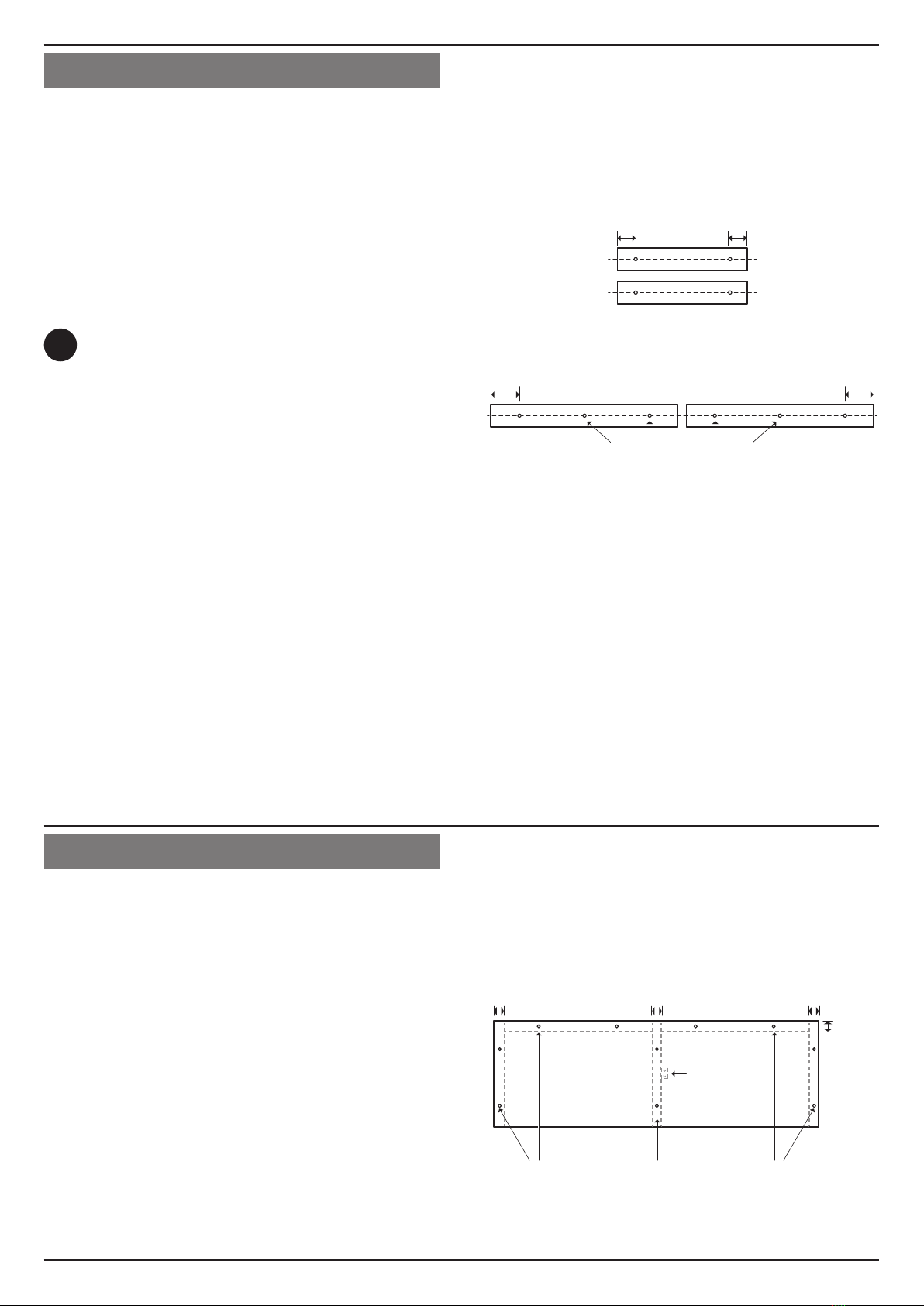
5. Fixing the hanging rails
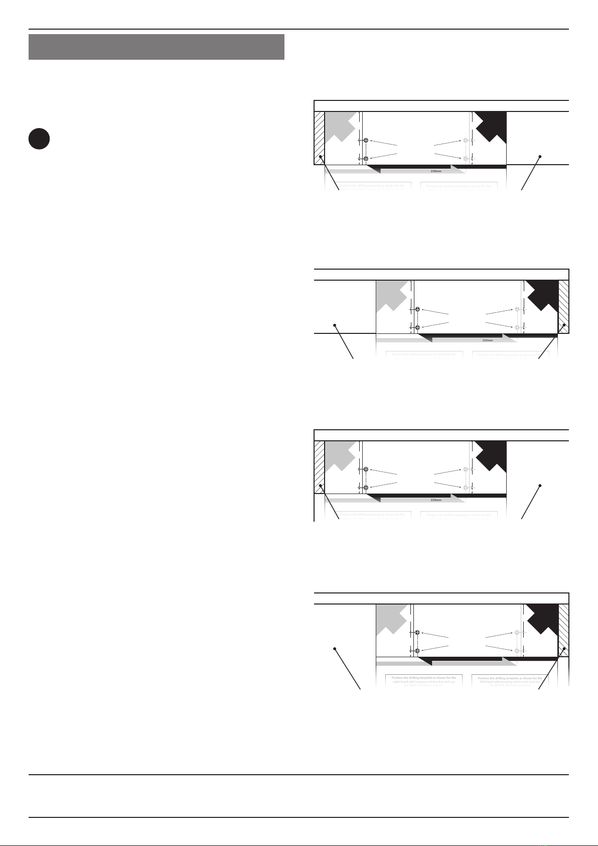
To ensure the two hanging rails are positioned
correctly, use the paper drilling template supplied. See
the diagrams 1 to 4to help you position the drilling
template correctly for each end of the hanging rails.
TIP You may wish to mark the positions for the pilot
holes with a bradawl, remove the template and
then drill the holes; rather than drilling the pilot
holes directly through the paper template.
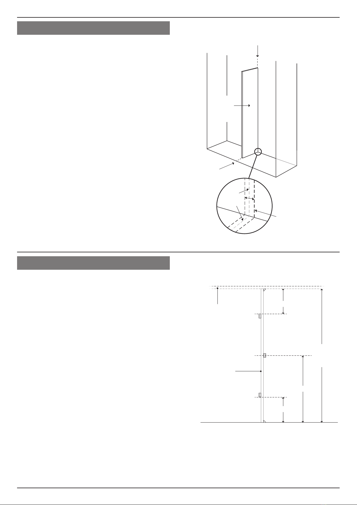
When drilling the pilot holes in the centre dividing
panel, take care not to drill completely through the
panel.
Once the pilot holes are drilled, place the hanging rail
brackets in position (ensuring the U-shaped cup is at
the bottom) and screw each one in place through the
top and bottom holes. Use the 16mm screws to secure
the brackets into the left and right shelf bearers; use the
10mm screws to secure the brackets into each side of
the centre dividing panel.
Measure the distance between the inside faces of the
hanging rail brackets in each side of the wardrobe and
cut each of the two hanging rails to these lengths. The
hanging rails can then be placed in position and should
sit securely in the U-shaped cups of the brackets.
230mm
230mm
Drill 2mm diameter
pilot holes
47mm30mm10
mm
47mm 30mm 10
mm
HANGING RAIL BRACKETS
DRILLING TEMPLATE
For use with PACKS D,E,F, G and H
Place in
back corner
under shelf on
right hand side
of wardrobe
Usethe
GREY
drillhole positions
Place in
back corner
under shelf on
left hand side
of wardrobe
Use the
BLACK
drillhole positions
Shelf
Shelf
Position the drilling template as shown for the
right hand side hanging rail bracket and use
the GREY drill hole positions
Position the drilling template as shown for the
left hand side hanging rail bracket and use
the BLACK drill hole positions
Back
shelf bearer
Right hand
shelf bearer
GREY drill hole
positions
BLACK drill hole
positions
Left hand
shelf bearer
Back
shelf bearer
1. Drilling template position for hanging rail bracket
on right hand shelf bearer
Right hand shelf bearerBack shelf bearer
Shelf
230mm
230mm
Drill 2mm diameter
pilot holes
47mm30mm10
mm
47mm 30mm 10
mm
HANGING RAIL BRACKETS
DRILLING TEMPLATE
For use with PACKS D,E,F, G and H
Place in
back corner
under shelf on
right hand side
of wardrobe
Usethe
GREY
drillhole positions
Place in
back corner
under shelf on
left hand side
of wardrobe
Use the
BLACK
drillhole positions
Shelf
Shelf
Position the drilling template as shown for the
right hand side hanging rail bracket and use
the GREY drill hole positions
Position the drilling template as shown for the
left hand side hanging rail bracket and use
the BLACK drill hole positions
Back
shelf bearer
Right hand
shelf bearer
GREY drill hole
positions
BLACK drill hole
positions
Left hand
shelf bearer
Back
shelf bearer
2. Drilling template position for hanging rail bracket
on left hand shelf bearer
Back shelf bearerLeft hand shelf bearer
Shelf
230mm
230mm
Drill 2mm diameter
pilot holes
47mm30mm10
mm
47mm 30mm 10
mm
HANGING RAIL BRACKETS
DRILLING TEMPLATE
For use with PACKS D,E,F, G and H
Place in
back corner
under shelf on
right hand side
of wardrobe
Usethe
GREY
drillhole positions
Place in
back corner
under shelf on
left hand side
of wardrobe
Use the
BLACK
drillhole positions
Shelf
Shelf
Position the drilling template as shown for the
right hand side hanging rail bracket and use
the GREY drill hole positions
Position the drilling template as shown for the
left hand side hanging rail bracket and use
the BLACK drill hole positions
Back
shelf bearer
Right hand
shelf bearer
GREY drill hole
positions
BLACK drill hole
positions
Left hand
shelf bearer
Back
shelf bearer
3. Drilling template position for hanging rail bracket on
left hand side of centre dividing panel
Centre dividing panelBack shelf bearer
Shelf
230mm
230mm
Drill 2mm diameter
pilot holes
47mm30mm10
mm
47mm 30mm 10
mm
HANGING RAIL BRACKETS
DRILLING TEMPLATE
For use with PACKS D,E,F, G and H
Place in
back corner
under shelf on
right hand side
of wardrobe
Usethe
GREY
drillhole positions
Place in
back corner
under shelf on
left hand side
of wardrobe
Use the
BLACK
drillhole positions
Shelf
Shelf
Position the drilling template as shown for the
right hand side hanging rail bracket and use
the GREY drill hole positions
Position the drilling template as shown for the
left hand side hanging rail bracket and use
the BLACK drill hole positions
Back
shelf bearer
Right hand
shelf bearer
GREY drill hole
positions
BLACK drill hole
positions
Left hand
shelf bearer
Back
shelf bearer
4. Drilling template position for hanging rail bracket
on right hand side of centre dividing panel
Back shelf bearerCentre dividing panel
Shelf
Other Wardrobe Doors Direct Indoor Furnishing manuals
Popular Indoor Furnishing manuals by other brands

Dell EMC
Dell EMC ES40 Field Replacement Unit Guide

SitTight
SitTight Chair Assembly instructions

Komfort & Wohnen
Komfort & Wohnen 4284 Assembly instructions

Accentrics Home
Accentrics Home DS-D229-054 Assembly instructions

Trasman
Trasman 6816A Bo3 Assembly manual

DURAVIT
DURAVIT XViu XV 7142 Mounting instructions

overstock
overstock WF286078 Assembly instructions

Habitat
Habitat Petale 821792 manual

sieger
sieger Auckland 428 Assembly instructions

CAFOM SOURCING
CAFOM SOURCING GFC-096 Note of assembly

Belleze
Belleze Bistro 014-HG-20062 Assembly instructions

Wholesale Interiors
Wholesale Interiors C6412A-030-5D Series Assembly instructions