WAREMA EWFS User manual

Operating and installation instructions
EWFS Plug receiver lighting
Keep for future use!
Valid from 01 September 2021
warema_2035334_alhb_en_v1•2021-09-01 We reserve the right to make technical modifications 1
General information
Fig. 1 EWFS Plug receiver lighting
The EWFS Plug receiver lighting enables the simple and
cost-effective retrofitting of a wireless remote control for
lighting equipment. This requires minor electrical work.
The plug receiver can receive move commands from
EWFS-compatible transmitters, e.g.
EWFS Hand-held transmitters or EWFS Timer.
Intended use
The EWFS Plug receiver lighting is an electronic device
for controlling lighting equipment. Any use other than the
purpose described in these instructions requires approval
from the manufacturer.
Safety instructions
ARNINGW
The electrical installation (assembly)/
dismantling must be performed by a certified
electrician in accordance with VDE 0100 or
the legal requirements and standards of the
country in which the device is being installed.
The electrician must observe the installation
instructions included with the electrical
devices supplied.
ARNINGW
If hazard-free operation cannot be assumed,
the device may not be commissioned or must
be decommissioned. This assumption is
justified if
the housing or connecting lines
appear damaged
if the device is no longer working.
ARNINGW
Switch off the supply voltage of the EWFS
Plug receiver when you perform activities on
products connected to the plug receiver or on
connected lighting equipment. Danger due to
sudden movements of the equipment or electric
shock.
AUTIONC
Never press the buttons on your transmitter
randomly without a line of sight to the sun shading
system. Children must not play with this product –
keep remote controls and transmitters out of the
reach of children!
Due to both the legal regulations for radio systems and
structural factors, the operating range of radio remote
controls is limited. Sufficient radio reception must be
ensured when planning the project. This is especially the
case where the radio signal has to pass through walls
and ceilings. The control should not be installed in the
immediate vicinity of metal components (steel beams,
reinforced concrete, fire doors).
Therefore, check that the receiver is functioning
properly before the final installation.
Strong local transmitter systems (e.g. baby monitors or
neighbouring transmitters) can interfere with the reception.
Switch the mains supply back on. The device is then
ready for operation.
Function
To switch on the light: If you are using an 8-channel
hand-held transmitter, select the correct channel using the
channel buttons. If you are using a 1-channel hand-held
transmitter, this step is not necessary. Press the B button
briefly: the lamp switches on.
To switch off the light:If you are using an 8-channel
hand-held transmitter, select the correct channel using the
channel buttons. If you are using a 1-channel hand-held
transmitter, this step is not necessary. Press and hold the
B button until the lamp switches off.
Symbols used
When the receiver is delivered, it does not "know" any
transmitters initially and therefore must learn to respond to the
correct transmitters. We refer to this process as "learning-in".
Explanation of symbols:
Power-up: In order to learn, you must electri-
cally isolate a receiver or a group of receivers,
either at the in-line circuit breaker or at the as-
sociated plug-in connector, and then reconnect
it again after approx. 5 seconds. (Power-up pro-
cedure.) Always perform a power-up procedure
when you see the in-line circuit breaker symbol.
The receiver is now in learn mode for approx.
one minute. The learn button on the transmitter
must be pressed during this time interval or the
receiver will exit the learn mode. Push the learn
button on your transmitter whenever you see
the learn button symbol.
The lamp lights up: After the learn button on
the transmitter is activated, the connected lamp
is switched on. Release the button immediately.
If you are operating a fluorescent lamp, release
the button as soon as the lamp first goes on.
Learning in the master channel
You can learn either a 1-channel transmitter or one
channel of an 8-channel transmitter into a receiver. With
an 8-channel transmitter, you simply need to make sure

warema_2035334_alhb_en_v1•2021-09-01We reserve the right to make technical modifications
2
that you first select the desired channel, as the following
example shows:
How to learn channel 1 of an 8-channel hand-held
transmitter into a receiver:
Put receiver in learn mode:
Perform the power-up pro-
cedure on the receiver.
Learn in the transmitter:
Take the transmitter, select
channel 1, press and hold
the learn button, the lamp
lights up, release the button.
Result:The receiver can now be operated with channel 1
of the transmitter.
Building a group
You would like to operate two lamps with an 8-channel
hand-held transmitter (I) as follows:
Channel1 controls lamp1 (master channel)
Channel2 controls lamp2 (master channel)
Channel3 controls both lamps together (auxiliary channel).
1
ΙΙ Ι
2
3
= Master channel = Auxiliary channel
1212
Fig. 2 Building a group
1st step: Learn in the master channel
One master channel must be learned into each receiver
before you can build a group. As described in the section
"Learning in the master channel", learn in channel 1 on
receiver 1 as a master channel and channel 2 on receiver
2 as a master channel.
If this is not possible because the power-up pro-
cedure cannot be performed separately for the
receivers, the master channels must be learned in
by means of "smart learning". For this purpose the
"EWFS Applications brochure" is available at:
https://warema.com/media/866089.pdf.
2nd step: Learn in the auxiliary channel
You can now operate the lamps separately, and each
learned channel is a master channel in the respective
receiver. If the learn button is pushed with this master
channel, the learn mode can be started and an auxiliary
channel learned into the respective receiver even without
the power-up procedure. If the same auxiliary channel, e.g.
channel 3, is now learned into each receiver, both lamps
can later be operated as a group with channel 3 but they
can still be operated separately via the master channels 1
and 2. The next step is to learn in the auxiliary channels:
Learning lamp 1 into channel 3
Place receiver1 into learn
mode: Select channel1,
press and hold the learn
button, lamp1 lights up,
release the button.
Learning in channel 3 as the
auxiliary channel: Select
channel 3. Press and hold
the learn button, lamp 1
lights up, release the button.
Channel 3 is now an auxilia-
ry channel for lamp 1.
1
Ι
1
Ι
3
Ι
Close learn mode: Select
channel1, button "B".
Result:Lamp1 now can also be operated with channel3.
Learning lamp 2 into channel 3
Place receiver2 into learn
mode: Select channel2,
press and hold the learn
button, lamp2 lights up,
release the button.
Learn in channel3 as an aux-
iliary channel: Select chan-
nel3, press and hold the
learn button, lamp2 lights
up, release the button.
Channel 3 is now an auxil-
iary channel for lamp 2.
Close learn mode: Select
channel2, press button "B".
Result:Lamp2 now can also be operated with channel3.
Deleting an auxiliary channel
You can delete all auxiliary channels learned into the
receiver if you made a mistake and want to start over
again. See the following example:
1
ΙΙ Ι
2
3
= Master channel = Auxiliary channel
1212
Fig. 3 Auxiliary channels in receiver 1 and 2 are to be deleted.
Carry out the following operation steps in succession
with the respective master channel:
Delete all auxiliary channels
in receiver 1: Select master
channel 1, press the learn
button and hold it for at
least 20 seconds; the lamp
lights up twice and then
stays off!
End the procedure: Select
channel1, press button "B".
Delete all auxiliary channels
in receiver 2: Select channel
2, push the learn button
and hold it for at least 20
seconds; the lamp lights up
twice and then stays off!
End the procedure: Select
master channel 2, press
button "B".
Result:All auxiliary channels in receiver1 and receiver2
were deleted.
Only one master channel and another 15 auxiliary
channels can be learned into each receiver. The
master channel cannot be deleted but can only
be overwritten with a new channel. The auxiliary
channels are not deleted when you learn in a new
master channel.
1
Ι
B
2
Ι
3
Ι
2
Ι
B
1
Ι
1
Ι
B
2
Ι
2
Ι
B
3
warema_2035334_alhb_en_v1•2021-09-01 We reserve the right to make technical modifications
Special functions
T
he WAREMA EWFS also enables a wide range of special
functions. Should you require further information, your
specialist dealer will be pleased to give you the application
brochure.
The A, B and C function buttons
Function button B on the transmitter can be used to switch
the lamp on and off. Buttons A and C do not have a
function on this receiver.
Installation
First switch off the mains supply at the upstream fuse.
Locate the plug-in connection for the lighting system,
release the safety catch and disconnect the coupling
and connector. Next, connect these to the EWFS Plug
receiver and lock the plug-in connection with the safety
catch.
The EWFS Plug receiver must not be exposed to direct
sunlight.
Route the cable in such a way that water cannot flow
along the cable into the device.
The EWFS Plug receiver must be mounted securely
(jolt-free mounting). If several EWFS Plug receivers are
in use, they must be mounted a minimum distance of
0.5m apart!
When mounting the plug receiver behind a metal
panel: Mount the plug receiver such that the side of
the housing with the printed radio symbol faces the
opening of the panel. This ensures the best possible
radio reception.
Special mounting housings in different colours are
available for protection from the weather and for discrete
installation of the EWFS Plug receiver on the facade.
Due to its larger dimensions, the EWFS Plug recei-
ver does not fit into the installation housings with
article numbers 317381, 317382 und 317383.
Initial operation
You can find instruction videos on our
YouTube channel at:
http://www.youtube.com/user/SonnenLichtManager/videos
After the device is connected, a light switch, if present,
must be engaged in the "On" setting and remain in
this setting. If you select a different setting, the power
supply to the device is interrupted and the light cannot
be switched on. After retrofitting, the switch can no
longer be used to operate the equipment. Therefore,
have your electrician electrically bridge your light
switch.
Maintenance
There are no parts inside the device that require
maintenance.
Liability
Failure to comply with the product information contained in
these instructions and any use of the device other than its
intended use and purpose may result in the manufacturer
refusing to honour warranty claims for product damage.
In this case, liability for secondary harm to persons or
damage to property will also be excluded.
Cleaning
Clean the housing with a soft, damp cloth. Do not use
detergents, cleaning agents, solvents, abrasive substances
or steam cleaners!
Disposal
After use, the device must be disposed of according to
legal regulations or turned in to your local recycling centre.
Technical data
EWFS Plug receiver
lighting min. typ. max. Unit
Supply 230 V AC
Operating voltage 85 230 265 V AC
Power consumption 0.3 0.5 W
Light output (non-floating)
Switching capacity at
230 V AC / cosϕ=0.6 700 VA
230 V AC bulbs 800 W
230 V AC halogen lamps 800 VA
LV halogen lamps with
electronic transformer 700 VA
Fluorescent lamps with
conventional ballast 700 VA
Fluorescent lamps with
electronic ballast 1000 VA
HF receiver
Receive frequency
ASK (OOK) 433.92 MHz
Operating range
(environment without
interference)
30 m
Ambient conditions
Operating temperature -20 60 °C
Storage temperature -25 70 °C
Humidity
(non-condensing) 10 85 %RH
Degree of soiling 2
Housing
Dimensions in mm
(L x D x H) 136 x 38 x 25
Degree of protection IP54
Safety class I
Miscellaneous
Conformity
Can be viewed at
www.warema.com/ce
This device complies with the EMC directives for use in
residential and commercial areas.
WAREMA Renkhoff SE declares herewith that this radio system
type EWFS Plug receiver lighting is in compliance with the
guideline 2014/53/EU.
Article numbers
EWFS Plug receiver lighting 2035 425
Mounting housing
White (similar to RAL 9016) 317 745
Grey (similar to RAL 9006) 317 748
Black (similar to RAL 9011) 317 751
WAREMA Renkhoff SE
Hans-Wilhelm-Renkhoff-Str. 2
97828 Marktheidenfeld
Germany

warema_2035334_alhb_en_v1•2021-09-01We reserve the right to make technical modifications
4
123
21
3
ACB
2
1➊
➋
Troubleshooting
EWFS Plug receiver lighting Help with malfunctions
Type of malfunction Possible cause Remedy
Transmission LED of the transmitter does
not light up
Battery inserted with wrong polarity or
depleted
Insert batteries correctly, read the
operating instructions, insert new batteries
Switch commands of the transmitter are not
executed
Transmitter has not been learned in Learn in the transmitter as described in the
instructions
The wrong channel was selected Select the correct channel and then repeat
the switch command
Interfering ambient influences Reduce the distance between the
transmitter and receiver
The receiver is not supplied with mains
voltage
Switch on the power supply
The wrong button was pressed The light is switched with button B
The light cannot be switched on The button was pressed too long Repeat the switch command, tap button B
The light cannot be switched off Button not pushed long enough Repeat the switch command, press and
hold button B
Switch commands are only carried out
sporadically
Interference caused by another transmitter Deactivate the other transmitter
(e.g. baby monitor)
There are reinforced concrete ceilings or
walls located between the transmitter and
receiver
Reduce the distance to the receiver
Fig. 4 Plug-in connection
A Coupling (on-site connection)
B EWFS Plug receiver
C Plug (consumer connection)
Neutral conductor (blue)
L phase (black)
Earth conductor (yellow/green)
Neutral conductor (blue)
L phase (black)
Earth conductor (yellow/green)
The brown wire of the cable is not required
and therefore not shown.
ARNINGW
The on-site fuse protection for the
EWFS Plug receiver must be rated
for the smallest (connected upstream
or downstream of the plug receiver)
conductor cross-section.
EXAMPLE When using a motor line type H05RR-F
4 G 0.75 connected downstream of the
EWFS Plug receiver, a 6A on-site fuse
protection for the power supply must be
provided.
Other WAREMA Receiver manuals

WAREMA
WAREMA EWFS Plug receiver PL User manual

WAREMA
WAREMA EWFS Inside PL User manual

WAREMA
WAREMA EWFS Piccolo PL User manual

WAREMA
WAREMA EWFS Piccolo FZL User manual

WAREMA
WAREMA EWFS Haustechnik FZL User manual

WAREMA
WAREMA EWFS Haustechnik PL User manual

WAREMA
WAREMA KNX EWFS User manual

WAREMA
WAREMA KNX EWFS User manual

WAREMA
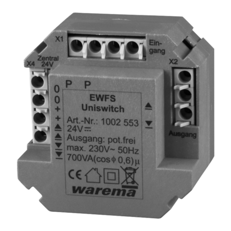
WAREMA EWFS Uniswitch User manual