Warner Electric 1100-42 User manual

Installation Instructions
P-1377
819-0090
Saf ty Br akaway Switch
No. 1100-42
OBSOLETE
ECN-101861
10/3/2018

2Warner Electric • 800-825-9050 P-1377 • 819-0090
Parts Includ d in Kit
BREAKAWY SWITCH ASSEMBLY
15 Amp Current Rating
with 2 or 4 Brakes
Typical Installation
BATT ERY
BREAKAWAY
SWITCH
BRAKE
WIRES
LANYARD
BRAKE
WIRES
FROM
TOWING
VEHICLE
TO TRAILER
BRAKES
BREAKAWAY
SWITCH
STORAGE
BATTE RY
Activated only in the event of a trailer breakaway
emergency, the breakaway switch remotely
activates the independent safety circuit of the
trailer brake systems. Sonic welded case
protects electrical component against water
and sun.
Recommended for recreational and light
commercial trailers. 12V. Up to four brake
capacity. Not polarity sensitive, + or – ground.
Consists of:
1 – Breakaway Switch
1 – ounting Accessory
1 – Installation Instruction
Cable & Pin Assembly
1100-253-002
Failur to follow th s
instructions may r sult in product
damag , quipm nt damag , and
s rious or fatal injury to p rsonn l.

3
Warner Electric • 800-825-9050 P-1377 • 819-0090
Installation Instructions for Warn r Saf ty
Br akaway Switch
15 Amp Curr nt Rating with 2 or 4 Brak s
Part Numb r 1100-42
The purpose of the Safety Breakaway Switch is
to minimize the possibility of an accident due to
a “runaway” trailer. If a trailer becomes detached
from the towing vehicle during transit, the switch
pin is pulled out by the lanyard. This closes the
circuit connecting the battery to the trailer
brakes, providing electricity to stop the trailer.
1. Position the breakaway switch on the trailer
frame with the pin pointing toward the
towing vehicle. Allow sufficient lanyard
length to attach the lanyard to the towing
vehicle. The lanyard should be long enough
to allow for turning corners, yet short
enough to disengage the pin from the switch
before the safety chains on the hitch
become taut in a trailer disconnect situation.
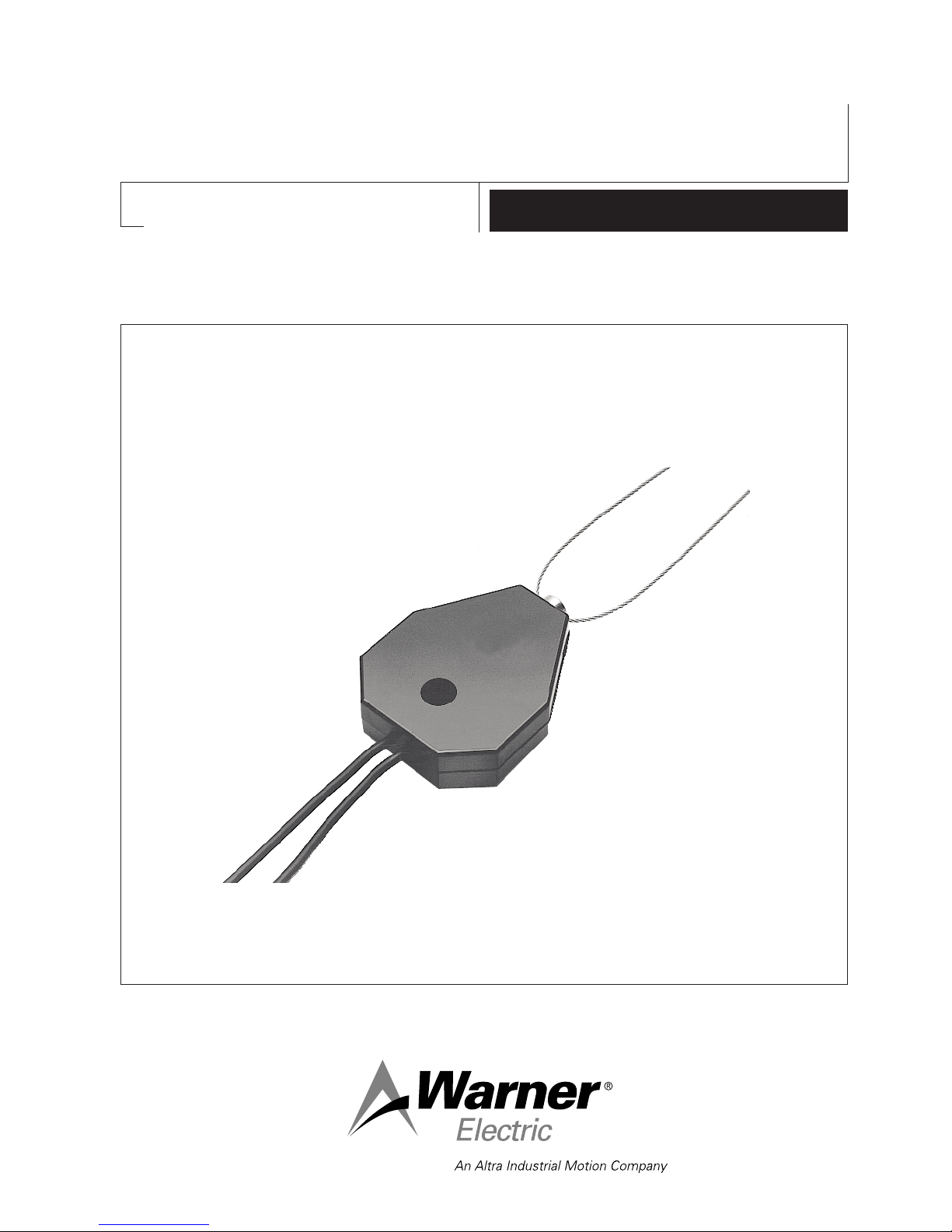
2. Position the Warner Safety Breakaway
Switch on any horizontal surface of the
tongue so the lanyard cable and breakaway
switch have no forward obstructions and
can swivel freely. Drill a 9/32" hole for the
attachment of the switch. Insert the metal
sleeve furnished into the mounting hole in
the switch and mount the switch on the
tongue using the bolt, nut, and lockwasher
provided. The sleeve will allow the switch to
pivot freely, assuring alignment of the
lanyard with the towing vehicle.
3. ount a battery on the trailer frame. The
battery must be the same voltage as the
trailer brakes and have adequate capacity to
meet legal requirements of the states in
which the trailer will be towed.
Not : An automotive-type storage battery
is preferred as the power source.
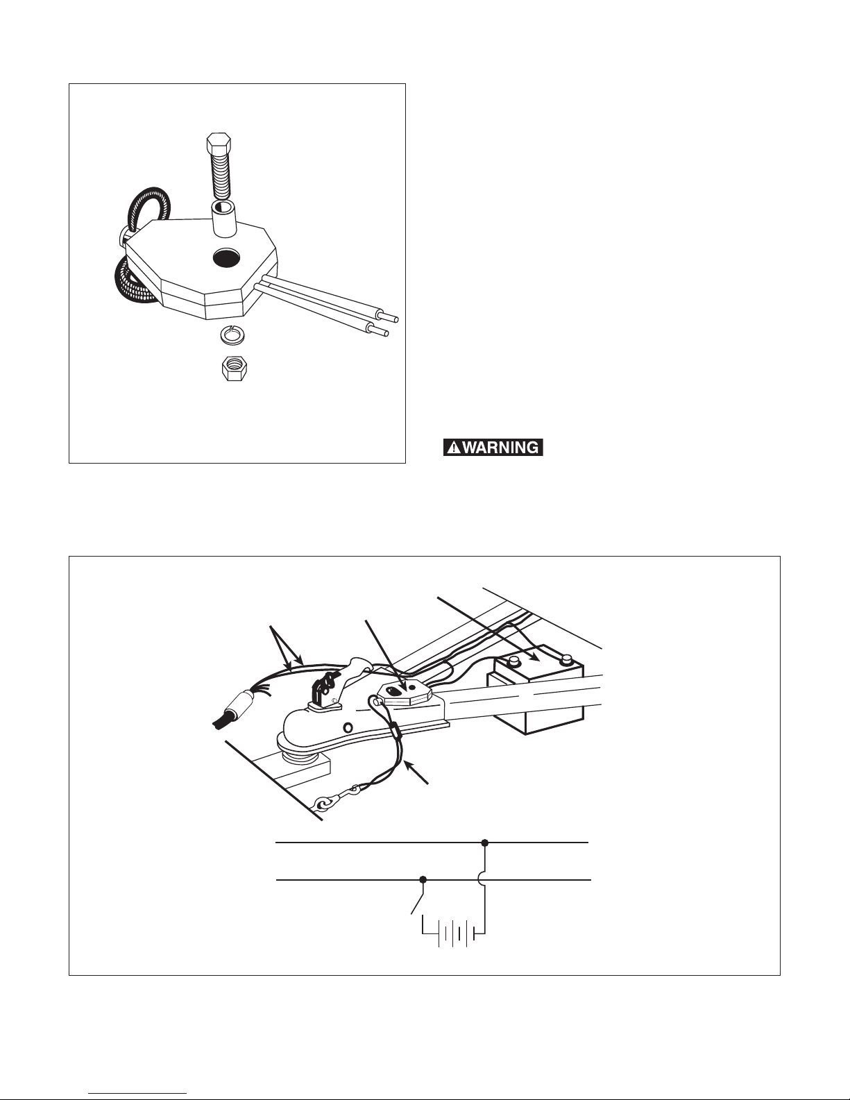
4. Connect one lead from the switch to one
of the battery terminals. Connect the other
battery terminal to one of the trailer brake
supply wires, matching the tow vehicle
pularity. Connect the other lead from the
switch to the remaining brake wire, leaving
enough slack for the switch to swivel (see
illustration). ake sure all terminals and
connections are secure and well insulated.
5. Fasten the lanyard to a convenient structural
member of the towing vehicle. Do not fasten
it to the hitch assembly. A snap hook and
eyebolt can be added to facilitate hookup
and removal of the lanyard.
Th syst m should b t st d
p riodically by pulling th pin and trying to
pull th trail r with th towing v hicl . Th
trail r brak s should b ngag d. Aft r
t sting, r turn th pin to th “full-in” position.
Avoid prolong d or fr qu nt activation of th
saf ty switch, sinc th batt ry is discharg d
wh n v r th switch is actuat d. Ch ck th
batt ry p riodically with a hydrom t r or
oth r suitabl batt ry t st r to assur that full
charg is maintain d in accordanc with th
batt ry manufactur r’s r comm ndations.

Warranty
Warner Electric LLC warrants that it will repair or replace (whichever it deems advisable) any
product manufactured and sold by it which proves to be defective in material or workmanship
within a period of one (1) year from the date of original purchase for consumer, commercial or
industrial use.
This warranty extends only to the original purchaser and is not transferable or assignable without
Warner Electric LLC’s prior consent.
Warranty service can be obtained in the U.S.A. by returning any defective product, transportation
charges prepaid, to the appropriate Warner Electric LLC factory. Additional warranty information
may be obtained by writing the Customer Satisfaction Department, Warner Electric LLC, 449
Gardner Street, South Beloit, Illinois 61080, or by calling 815-389-3771.
A purchase receipt or other proof of original purchase will be required before warranty service is
rendered. If found defective under the terms of this warranty, repair or replacement will be made,
without charge, together with a refund for transportation costs. If found not to be defective, you will
be notified and, with your consent, the item will be repaired or replaced and returned to you at
your expense.
This warranty covers normal use and does not cover damage or defect which results from
alteration, accident, neglect, or improper installation, operation, or maintenance.
Some states do not allow limitation on how long an implied warranty lasts, so the above limitation
may not apply to you.
Warner Electric LLC’s obligation under this warranty is limited to the repair or replacement of the
defective product and in no event shall Warner Electric LLC be liable for consequential, indirect,
or incidental damages of any kind incurred by reason of the manufacture, sale or use of any
defective product. Warner Electric LLC neither assumes nor authorizes any other person to give
any other warranty or to assume any other obligation or liability on its behalf.
WITH RESPECT TO CONSU ER USE OF THE PRODUCT, ANY I PLIED WARRANTIES WHICH
THE CONSU ER AY HAVE ARE LI ITED IN DURATION TO ONE YEAR FRO THE DATE OF
ORIGINAL CONSU ER PURCHASE. WITH RESPECT TO CO ERCIAL AND INDUSTRIAL
USES OF THE PRODUCT, THE FOREGOING WARRANTY IS IN LIEU OF AND EXCLUDES ALL
OTHER WARRANTIES, WHETHER EXPRESSED OR I PLIED BY OPERATION OF LAW OR
OTHERWISE, INCLUDING, BUT NOT LI ITED TO, ANY I PLIED WARRANTIES OF
ERCHANTABILITY OR FITNESS.
Some states do not allow the exclusion or limitation of incidental or consequential damages, so the
above limitation or exclusion may not apply to you. This warranty gives you specific legal rights and
you may also have other rights which vary from state to state.
Chang s in Dim nsions and Sp cifications
All dimensions and specifications shown in Warner Electric catalogs are subject to change without
notice. Weights do not include weight of boxing for shipment. Certified prints will be furnished
without charge on request to Warner Electric.
Warner Electric LLC
31 Industrial Par Road • New Hartford, CT 06057
815-389-3771 • Fax: 815-389-2582
www.warnerelectric.com
P-1377 • 819-0090 6/12 Printed in USA
Popular Switch manuals by other brands

ZyXEL Communications
ZyXEL Communications ExtraSmart ES-1552 release note

EMC
EMC Connectrix DS-24M2 installation guide

Briggs & Stratton
Briggs & Stratton 50A NEMA 1 Installation and owner's manual

Amulet Hotkey
Amulet Hotkey K4u quick start guide

Cisco
Cisco Nexus 3000 series Configuration guide

Belkin
Belkin F1DN002MOD-KM-4 user manual