Wassp WASP-038 User manual

WASSP WSP-038 IMU
INSTALLATION MANUAL

Page 2 of 24 Page 3 of 24Doc: WSP-038 IMU INSTALLATION MANUAL
Version: 1.4 December 2019
Doc: WSP-038 IMU INSTALLATION MANUAL
Version: 1.4 December 2019
wassp.com wassp.com
WSP-038 IMU INSTALLATION MANUALWSP-038 IMU INSTALLATION MANUAL
General Notices
WASSP Ltd. reserves the right to change the contents of this manual and any system
specifications without notice.
Contact WASSP Ltd. regarding copying or reproducing this manual.
Support information
If you require maintenance or repair, contact your local dealer. You can also contact
WASSP Ltd. using the following address: wassp.com/support/.
If you need information about WASSP products, visit wassp.com.
On the website you will also find a list of WASSP dealers and distributors.
Warnings, Cautions, and Notes
Warnings, cautions, and notes are indicated by the following icons throughout this
manual:
CAUTION indicates that if the instruction is not heeded, the action may result
in equipment damage or software corruption.
NOTE indicates a TIP or additional information that could be helpful while
performing a procedure.
Safety Instructions for the Installer
CAUTION: Turn o power at the switchboard before beginning installation.
Fire or electrical shock can result if power is left on.
CAUTION: Be sure that the power supply is compatible with the voltage rating
of the equipment.
Connecting to incompatible power supply can cause fire or
damage to the equipment.
CAUTION: Do not open the equipment.
Only qualified personnel should work inside the equipment.
WASSP WSP-038 IMU
INSTALLATION MANUAL
The WASSP WSP-038 IMU is a motion sensor that can be used with G3 WASSP
Multibeam systems.
It is designed for ease of installation and simplified system configuration through
direct connection to the WASSP DRX (WASSP Smart transceiver used with G3 WASSP
Multibeam) .
The WSP-038 supplies roll, pitch and heave attitude data required by the DRX, and should
be used alongside an appropriate Satellite Compass to supply position, heading and
speed to the DRX.
Refer to the DRX Installation Manual for full details on system configuration.
NOTE: WSP-038 IMU is compatible with:
- F3 and S3 #389+
- F3X #1+
NOTE: Supply 12V or more to F3/S3 when using WSP-038. Use a 24V supply
to power the DRX when using WSP-038 with a 20m extension cable.
DOCUMENT REVISION HISTORY
REVISION DATE REASON FOR CHANGE VERSION
September 2018 Compilation 1.0
January 2019 Update to Interconnections 1.1
April 2019 Update for Ethernet Conguration 1.2
June 2019 Update to V123 Conguration and Appendix A.4 1.3
December 2019 Update to cable and interconnections 1.4
RELATED DOCUMENTS
»DRX Installation Manual; Shipped with DRX
»Satellite Compass Installation Manuals as required
»Furuno IF-NMEASC Operators Manual as required
RELATED TOOLS
»WSP-038 Configuration App
»Satellite Compass Configuration SW
Further documentation can be found at wassp.com

Page 4 of 24 Page 5 of 24Doc: WSP-038 IMU INSTALLATION MANUAL
Version: 1.4 December 2019
Doc: WSP-038 IMU INSTALLATION MANUAL
Version: 1.4 December 2019
wassp.com wassp.com
WSP-038 IMU INSTALLATION MANUALWSP-038 IMU INSTALLATION MANUAL
CONTENTS
1 Interconnection diagrams 6
2 Components 7
2.1. WSP-038 IMU 7
2.2. WSP-038 Extension Cable - Optional 7
3 WSP-038 Mounting 8
4 WASSP Connection and Configuration 9
4.1. Satellite Compass Connection and Configuration 9
4.1.1. Satellite Compass Connection 9
4.1.2. Satellite Compass Configuration Requirements 9
4.1.3. Furuno SC Configuration 9
4.1.4. WASSP V123 Configuration 10
4.1.5. Hemisphere V103 11
4.2. WSP-038 Connection 11
4.3. DRX Configuration 12
4.3.1. Configuring for WSP-038 with Furuno SC 13
4.3.2. Configuring for WSP-038 with WASSP V123 14
5 Appendix 15
FIGURES
Figure 1. Interconnection Diagram, Furuno SC Option 6
Figure 2. Interconnection Diagram, WASSP V123 Option 6
Figure 3. WSP-038 IMU 7
Figure 4. S3/F3/F3X WSP-038 Connections 12
Figure 5. WSP-038 Configuration Setup 17
APPENDIX
Appendix A - Interconnections 15
Appendix A.1 DRX RS422-A To Satellite Compass 15
Appendix A.2 DRX RS422-B To WSP-038 16
Appendix A.3 WSP-038 Configuration 17
Appendix A.4 Lever Arm configuration 18
Appendix B - WSP-038 IMU Dimensions 19
Appendix C - Specifications 20

Page 6 of 24 Page 7 of 24Doc: WSP-038 IMU INSTALLATION MANUAL
Version: 1.4 December 2019
Doc: WSP-038 IMU INSTALLATION MANUAL
Version: 1.4 December 2019
wassp.com wassp.com
WSP-038 IMU INSTALLATION MANUALWSP-038 IMU INSTALLATION MANUAL
1 INTERCONNECTION DIAGRAMS
Furuno SC
WSP-038
DRX
RS422-A
RS422-B
IF-NMEASC
WSP-400-215
Optional Extension Cable
RS422A Up @ 38400
- HDT
- RMC
- ZDA
RS422 Down @ 38400
- TSS1
12-30VDC (WSP-038 Supply)
RS422 Down @ 38400
- HDT
- RMC
- ZDA
IF-NMEASC #8
WSP-400-259 WSP-002-120
Figure 1. Interconnection Diagram, Furuno SC Option
WASSP V123
Satellite
Compass
WSP-038
DRX
RS422-A
RS422-B
WASSP IF-SC
WSP-400-215
Optional Extension Cable
RS422A Up @ 38400
- GGA
- HDT
- VTG
- ZDA
RS422 Down @ 38400
- TSS1
12-30VDC (WSP-038 Supply)
RS422 Down @ 38400
- GGA
- HDT
- VTG
- ZDA
PPS
12-30VDC (SC Supply)
Applicable to F3 #389+
Applicable to all F3X
WSP-400-259
WSP-400-274
WSP-002-120
WSP-002-106
Figure 2. Interconnection Diagram, WASSP V123 Option
NOTE: Satellite Compass should be connected to DRX RS422-A not
NMEA0183 or RS232.
2 COMPONENTS
2.1. WSP038 IMU
P/N WSP-002-120
Preconfigured WASSP IMU with direct connection to DRX.
Figure 3. WSP-038 IMU
2.2. WSP038 EXTENSION CABLE OPTIONAL
P/N WSP-400-215
Optional 20m Extension Cable from WSP-038 to DRX.

Page 8 of 24 Page 9 of 24Doc: WSP-038 IMU INSTALLATION MANUAL
Version: 1.4 December 2019
Doc: WSP-038 IMU INSTALLATION MANUAL
Version: 1.4 December 2019
wassp.com wassp.com
WSP-038 IMU INSTALLATION MANUALWSP-038 IMU INSTALLATION MANUAL
3 WSP-038 MOUNTING
The WSP-038 should be installed taking the following into consideration:
»Accurate measurements need to be taken from the WSP-038, reference point,
transducer and the Satellite compass. Typically cm accuracy is recommended to
achieve acceptable multibeam performance. Refer to the DRX Installation Manual
for details on system commissioning and the ship’s measurements.
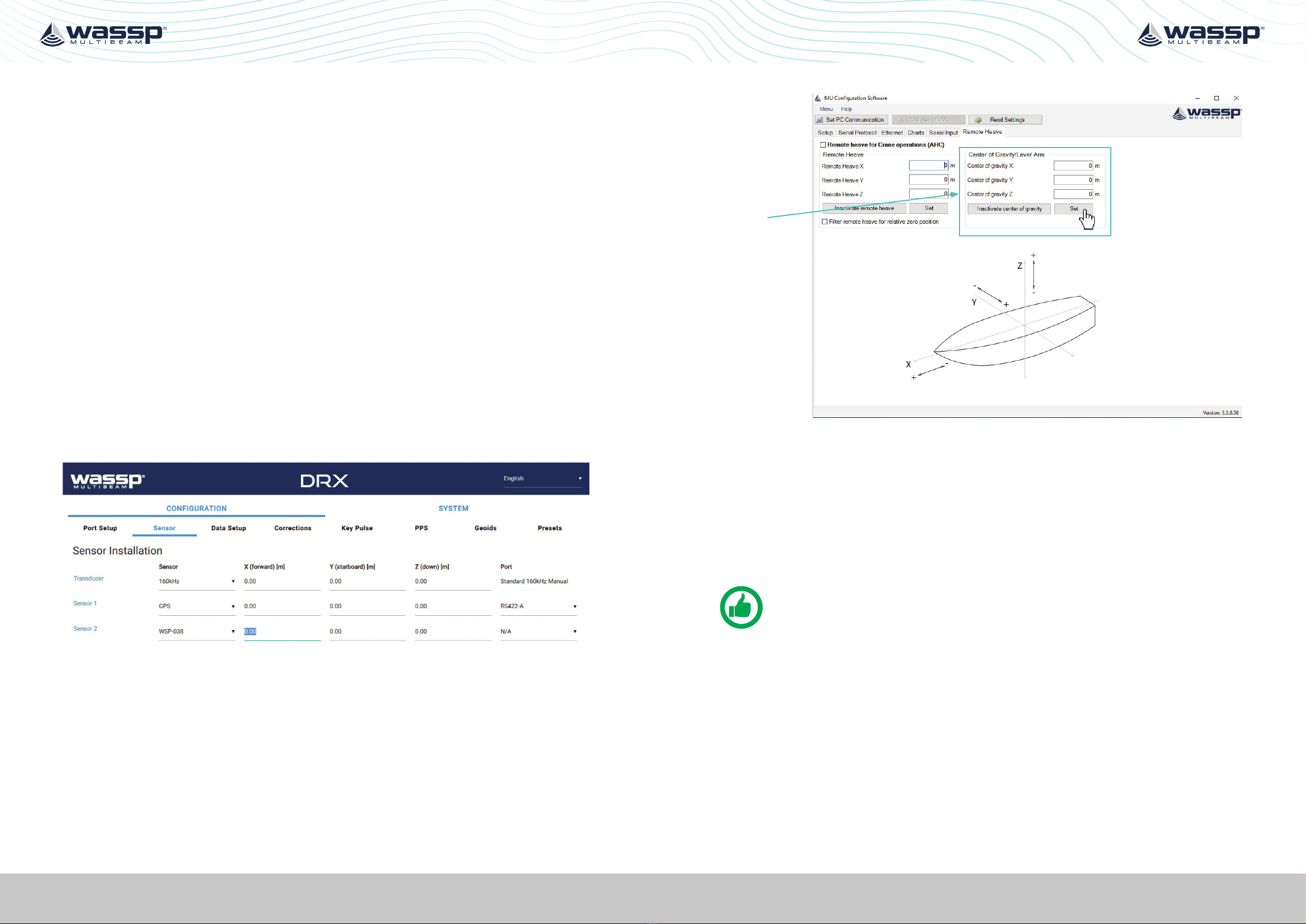
»The WSP-038 should be as close to the vessel’s centre of motion as possible
(usually very close to the vessel centre of gravity). If mounting close to the vessel’s
centre of motion is not practical then use the Ethernet port to configure Lever
Arm corrections for the sensor. See “Appendix A.4 Lever Arm configuration” on
page 18 (and “Appendix A.3 WSP-038 Configuration” on page 17 to establish
connection). This will give optimum motion sensor performance which is required
to achieve acceptable multibeam performance.
»Cabling from the DRX and Satellite compass needs to be accessible.
»A flat, rigid mounting location is required for optimum motion sensor performance.
»The WSP-038 should be located where it will not move and is not exposed to
vibration or other influences that could impact IMU performance.
»WSP-038 needs to be mounted accurately in fore/aft vessel orientation as per the
arrow on the WSP-038. The unit should be mounted closely aligned to the vessel
orientation.
• Heading accuracy +/-1 degrees
• Pitch accuracy +/-2 degrees. Any oset should be adjusted for during
commissioning
• Roll accuracy +/-2 degrees. Any oset should be adjusted for during
commissioning
NOTE: The WSP-038 needs to be mounted aligned fore/aft as per the arrow
on the box.
NOTE: Full commissioning should be carried out as per the DRX Installation
Manual to account for angular osets.
4 WASSP CONNECTION AND CONFIGURATION
Refer to “1 Interconnection diagrams” on page 6 for system configuration.
4.1. SATELLITE COMPASS CONNECTION AND CONFIGURATION
4.1.1. Satellite Compass Connection
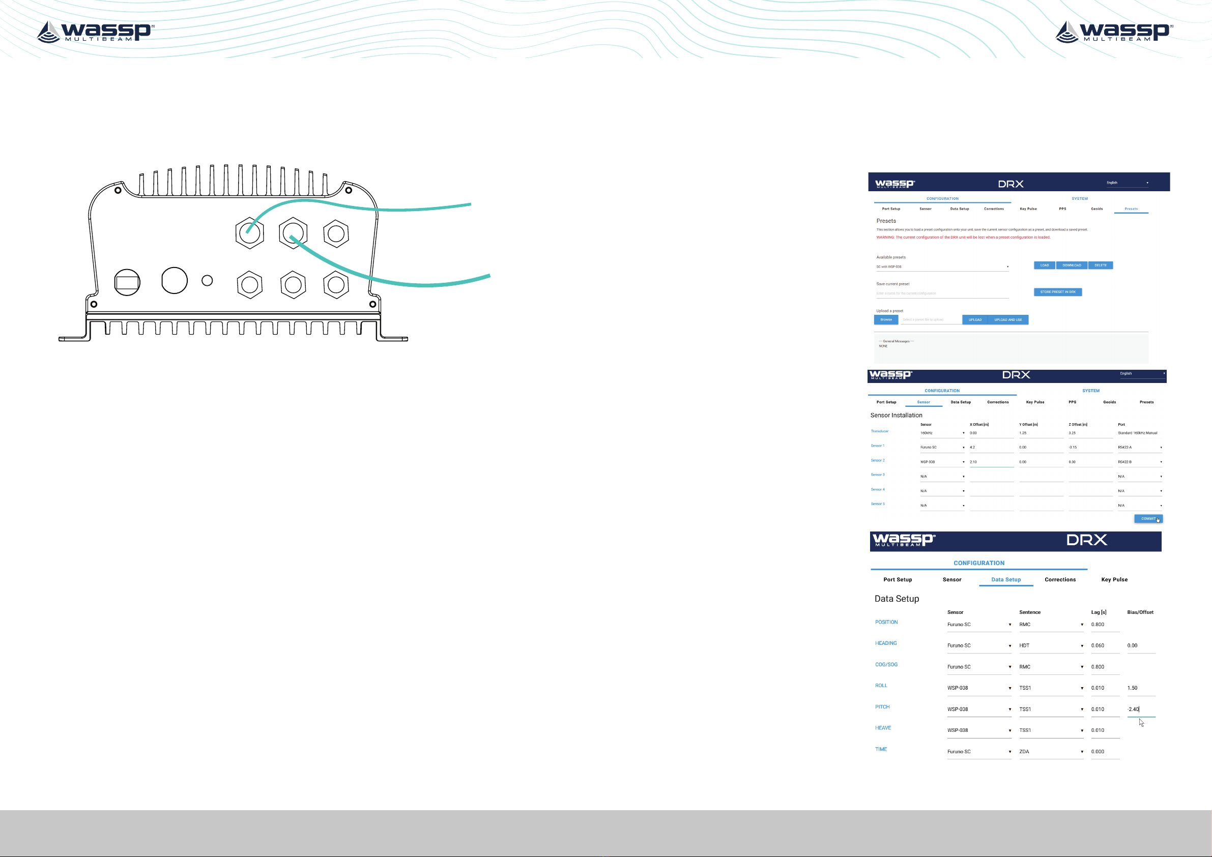
The Satellite Compass should be connected to the DRX connector RS422-A on the DRX
Back Plate.
Connect the RS422-A Satellite Compass Cable, P/N WSP-400-259, to the DRX RS422-A
connector and to the Satellite Compass interface box. The Satellite Compass Interface
Box will depend on Satellite Compass type and configuration.
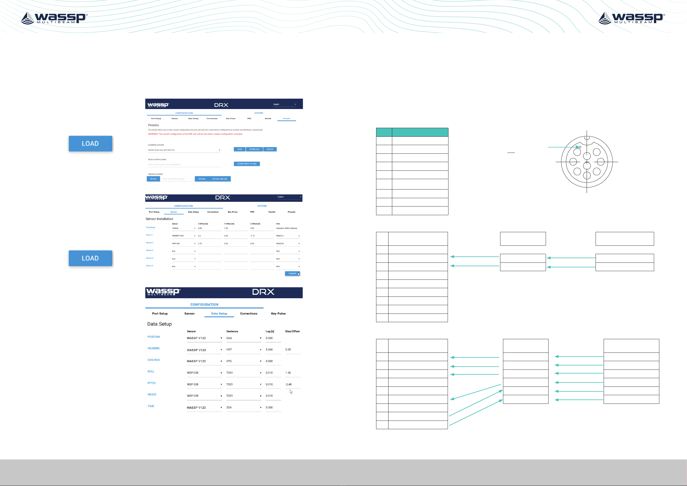
See “Appendix A.1 DRX RS422-A To Satellite Compass” on page 15 for required
interconnect.
4.1.2. Satellite Compass Configuration Requirements
Satellite Compass should be configured:
»Baud; 38400
»Position:
• Rate; Minimum 1Hz, Recommended 20Hz
• Sentences; GGA, GLL, RMC
»Heading:
• Rate; Minimum 20 Hz
• Sentences; HDT
»Speed:
• Rate; Minimum 1 Hz, Recommended 2 Hz
• Sentences; RMC, VTG
»Time:
• ZDA at 1 Hz
• PPS recommended
4.1.3. Furuno SC Configuration
The Furuno SC should be set up to output NMEA0183. Refer to the appropriate Furuno
SC manuals for mounting and configuration details.
Configuration setup will depend on the specific Furuno SC but will need to meet the
minimum criteria specified in “4.1.2. Satellite Compass Configuration Requirements” on
page 9 for the port connected to DRX RS422-A.
See “Appendix A.1 DRX RS422-A To Satellite Compass” on page 15 for Satellite
Compass Interconnect.

Page 10 of 24 Page 11 of 24Doc: WSP-038 IMU INSTALLATION MANUAL
Version: 1.4 December 2019
Doc: WSP-038 IMU INSTALLATION MANUAL
Version: 1.4 December 2019
wassp.com wassp.com
WSP-038 IMU INSTALLATION MANUALWSP-038 IMU INSTALLATION MANUAL
If using the Furuno Interface unit, IF-NMEASC, refer to the IF-NMEASC Operator’s Manual.
1. Connect the RS422-A Satellite
Compass Cable, P/N WSP-400-259,
from J5 (NMEA0183) on the
IF-NMEASC unit to RS422-A on the
DRX.
2. Select Sentence number 8 from J5 at
38400 bps.
a. HDT Output Interval 25 ms.
b. RMC Output Interval 1000 ms (or
higher if available).
c. ZDA Output Interval 1000 ms.
DRX
RS422-A
WSP-400-259
NOTE: J4 (NMEA0183) on IF-NMEASC can be used instead of J5 (NMEA0183).
CAUTION: Prepare, terminate and connect WSP-400-259, RS422-A to Satellite
Compass cable, to the Furuno SC before connecting to DRX RS422-A.
4.1.4. WASSP V123 Configuration
WASSP V123 will be supplied preconfigured from WASSP and should be mounted Fore/
Aft for true heading. See “Appendix A.1 DRX RS422-A To Satellite Compass” on page
15 for Satellite Compass Interconnect.
Typical configuration will be:
» Port B (RS422): 38400 Baud
• GGA 25Hz
• VTG 5Hz
• ZDA 1Hz
• HDT 25Hz
»PPS Out
»Port A (RS422); 38400 Baud
• GGA 25Hz
• VTG 5Hz
• ZDA 1Hz
• HDT 25Hz
DRX
WASSP
IF-SC RS422-A
WSP-400-259
WSP-400-274
V123 Port A
to Navigation Kit
WASSP V123
V123 Port B
Port B should be used as dedicated connection to the DRX RS422-A Port.
Port A can be used with other devices on the vessel for navigation.
4.1.5. Hemisphere V103
Reference the Hemisphere V103 Installation Manual for mounting and configuration
details.
Hemisphere V103 will be supplied preconfigured from WASSP and should be mounted
Fore/Aft for true heading.
Configuration setup will be:
»Port B (RS422): 38400 Baud
• GGA 20Hz
• VTG 2Hz
• ZDA 1Hz
• HDT 20Hz
»PPS Out
Port B should be used as dedicated connection to the DRX RS422-A Port.
4.2. WSP038 CONNECTION
The WSP-038, P/N WSP-002-120, connects directly to the DRX connector RS422-B.
If required the cable for DRX to WSP-038 can be extended using the optional WSP-038
Extension Cable, P/N WSP-400-215.
See “Appendix A.2 DRX RS422-B To WSP-038” on page 16 for the WSP-038
interconnect.
WSP-038 comes preconfigured and does not require any install specific configuration.
WSP-038 connectivity:
»Baud; 38400
»Output Rate: 100Hz
»Sentence; TSS1
For diagnostics purposes the WSP-038 can be reconfigured.
See “Appendix A.3 WSP-038 Configuration” on page 17 for configuration setup.
The WSP-038 has both RS232 & RS422 outputs, and can be wired to other interfaces. To
do so, just cut o the moulded cable plug and re-wire to other interface ports.
See “Appendix A.2 DRX RS422-B To WSP-038” for WSP-038 wiring functions.

Page 12 of 24 Page 13 of 24Doc: WSP-038 IMU INSTALLATION MANUAL
Version: 1.4 December 2019
Doc: WSP-038 IMU INSTALLATION MANUAL
Version: 1.4 December 2019
wassp.com wassp.com
WSP-038 IMU INSTALLATION MANUALWSP-038 IMU INSTALLATION MANUAL
4.3. DRX CONFIGURATION
Connect the WSP-038 and Satellite Compass to the DRX as per “1 Interconnection
diagrams” on page 6.
AUXN2K
POWER
LAN 0183
RS232
RS422-A RS422-B
Satellite Compass
WSP-038
Figure 4. S3/F3/F3X WSP-038 Connections
For sensor configuration on the DRX refer to the DRX Installation Manual.
Configure the DRX using the DRX SETUP WEBPAGES.
Using the WSP-038 PRESET the sensor setup can be automated for PORT SETUP, DATA
SETUP, CORRECTIONS AND PPS.
Sensor osets will need to be input manually using the SENSOR configuration page.
Sensor biases (angular osets) will need to be input manually using the DATA SETUP
CONFIGURATION page or using appropriate automated path tests.
Refer to the DRX Installation Manual for full details.
4.3.1. Configuring for WSP-038 with Furuno SC
1. With the system fully connected with all sensors powered on open the DRX SETUP
WEBPAGES.
2. Select CONFIGURATION and open the PRESETS tab.
3. Under AVAILABLE PRESETS
select SC WITH WSP-038 and
select LOAD.
4. Setup the sensor osets
under the SENSOR tab,
following the instructions in
the DRX Installation Manual.
5. Setup the Sensor Biases
under the DATA SETUP tab,
following the instructions in
the DRX Installation Manual.

Page 14 of 24 Page 15 of 24Doc: WSP-038 IMU INSTALLATION MANUAL
Version: 1.4 December 2019
Doc: WSP-038 IMU INSTALLATION MANUAL
Version: 1.4 December 2019
wassp.com wassp.com
WSP-038 IMU INSTALLATION MANUALWSP-038 IMU INSTALLATION MANUAL
4.3.2. Configuring for WSP-038 with WASSP V123
1. With the system full connected with all sensors powered on open the DRX SETUP
WEBPAGES.
2. Select CONFIGURATION and open the PRESETS tab.
3. Under AVAILABLE PRESETS
select WASSP V123 WITH
WSP-038 and select LOAD.
4. Setup the sensor osets
under the SENSOR tab,
following the instructions in
the DRX Installation Manual.
5. Setup the Sensor Biases
under the DATA SETUP tab,
following the instructions in
the DRX Installation Manual.
5 APPENDIX
APPENDIX A - INTERCONNECTIONS
APPENDIX A.1 DRX RS422A TO SATELLITE COMPASS
Connector RS422-A on DRX
PIN Function
1
2
345
6
7
8
9
Marker identifies pin 1.
View: Looking into the socket on the
DRX. Wiring view of cable side on plug.
1 PPS (AUX)
2 RxD B
3 RxD A
4 TxD B
5 TxD A
6 GND Isolated
7
8 9-30V+
9 9-30V-
Satellite Compass Connection for Furuno SC:
RS422-A WASSP IF-SC
(Optional) Furuno SC
1 PPS (AUX)
2 RxD B DRX Rx + (B) TxD B
3 RxD A DRX Rx - (A) TxD A
4 TxD B
5 TxD A
6 GND Isolated
7
8 9-30V +
9 9-30V -
Satellite Compass Connection for WASSP V123:
RS422-A WASSP IF-SC
(Optional) WASSP V123
1 PPS (AUX) PPS + PPS
2 RxD B DRX Rx + (B) TxD +
3 RxD A DRX Rx - (A) TxD -
4 TxD B PPS - PPS GND
5 TxD A POWER + PWR +
6 GND Isolated POWER - PWR -
7
8 9-30V +
9 9-30V -
Blue / White
White / Blue
Red / Blue Orange
Blue/ White
White / Blue
Blue / Red
Brown / White
Brown
Yellow
Yellow / Black
Orange / Black
Red
Black

Page 16 of 24 Page 17 of 24Doc: WSP-038 IMU INSTALLATION MANUAL
Version: 1.4 December 2019
Doc: WSP-038 IMU INSTALLATION MANUAL
Version: 1.4 December 2019
wassp.com wassp.com
WSP-038 IMU INSTALLATION MANUALWSP-038 IMU INSTALLATION MANUAL
APPENDIX A.2 DRX RS422B TO WSP038
Connector RS422-B on DRX
PIN Function
10
9
1
2
12
11 83
7
6
5
4
View: Looking into the socket on the
DRX. Wiring view of cable side on plug.
1 PPS (AUX)
2 RxD B
3 RxD A
4 TxD B
5 TxD A
6 GND
7 RESERVED
8 RESERVED
9 RESERVED
10 RESERVED
11 9-30V -
12 9-30V +
WSP-038 Connection:
RS422-B WSP-038
1 PPS (AUX)
2 RxD B TxD +
3 RxD A TxD -
4 TxD B RxD +
5 TxD A RxD -
6 GND RxD +
7 RESERVED RxD -
8 RESERVED PWR -
9 RESERVED PWR+
10 RESERVED
11 9-30V -
12 9-30V +
NOTE: used for configuration. See “Appendix A.3 WSP-038
Configuration” on page 17.
WSP-038 Wiring function:
WSP-038 Function Colour RS422 Rx+ Auxiliary Blue/White
Power + Brown/White RS422 Rx- Auxiliary White/Blue
Power - Brown RS232 Rx White/Grey
RS422 Rx+ Orange/White RS232 Tx Red/Blue
RS422 Rx- White/Orange RS232 Rx Auxiliary Grey/White
RS422 Tx+ Green/White SIG_GND Blue/Red
RS422 Tx- White/Green
When referring to colour code of wires, the first colour is the primary colour of the cable
and the second is the stripe. Eg. Grey/White is a Grey wire with a white stripe and White/
Grey is a white wire with a Grey stripe.
APPENDIX A.3 WSP038 CONFIGURATION
The WSP-038 can be configured using network.
Furuno SC
WSP-038
Config SW
WSP-038
DRX
RS422-A
RS422-B
IF-NMEASC
RJ45 Cable Configuration PC
Network Switch
WSP-400-259
WSP-002-120
Figure 5. WSP-038 Configuration Setup
To configure or diagnose issues:
1. Setup the system as per “Figure 5. WSP-038 Configuration Setup” on page 17.
2. Power on the DRX. The DRX supplies power to the WSP-038.
3. Power on the Satellite Compass. Satellite Compass input is required for WSP-038
operation.
4. Use a network cable to connect WSP-038 to the switch.
5. Set up PC static IP.
»» Open PC network & internet settings.
»» Set TCP/IPv4 properties as shown here, then click “OK”.
Green / White
White / Green
Brown
Brown / White
Orange / White
Blue / White
White / Blue
White / Orange

Page 18 of 24 Page 19 of 24Doc: WSP-038 IMU INSTALLATION MANUAL
Version: 1.4 December 2019
Doc: WSP-038 IMU INSTALLATION MANUAL
Version: 1.4 December 2019
wassp.com wassp.com
WSP-038 IMU INSTALLATION MANUALWSP-038 IMU INSTALLATION MANUAL
The lever arm is used to compensate for rotational accelerations. For example, if you
have a vessel where the motion sensor is located on the bridge with a Z distance from
the rotational point of the vessel that has large roll motion. The lever arm would then
calculate the lateral accelerations generated from the rotation acceleration and remove
this factor from its calculations which improves the angle output during these conditions.
The longer the distance is from the center of rotation the bigger the eect is mainly on
fast motions so the roll is normally the main parameter.
NOTE: DO NOT USE REMOTE HEAVE settings as this could lead to double
accounting of ship osets.
6. Run the WSP-038 CONFIG SW.
If the WSP-038 Config SW does not automatically connect, follow steps below:
»Select the SET PC COMMUNICATION Tab.
»Click USE ETHERNET FOR COMMUNICATION
»Click NETWORK SCAN and you will see the WSP-038 IP 172.16.1.100, click to
connect.
»Select USE SELECTED then SAVE CHANGES.
7. In the WSP-038 Config SW, SETUP, SERIAL PROTOCOL and SERIAL INPUT should
be checked to confirm data.
Contact WASSP Support or your local dealer for support or WSP-038 diagnosing issues.
APPENDIX A.4 LEVER ARM CONFIGURATION
ENTERING OFFSET MEASUREMENT IN THE WASSP SYSTEM DRX AND
WSP-038
Measurements In WASSP DRX to be entered via Commissioning
Application:
»If the sensor is located aft of the reference point the X measurement is negative.
»If the sensor is located to port of the reference point the Y measurement is negative.
»If the sensor is located above the reference point the Z measurement is negative.
Measurements in WSP-038 Motion sensor to be entered via Sensor direct
Ethernet Connection:
If the motion sensor is located a significant distance from the Centre of Gravity, for
example mounted on the bridge of a large vessel, it is possible to enter an oset to
reduce acceleration errors. If the motion sensor is located high on a large vessel the
most significant factor will be the Z measurement.
Important note for leaver arm settings in the WSP-038:
»If the motion sensor is located aft of the COG the X measurement is positive.
»If the motion sensor is located to port of the COG the Y measurement is negative.
»If the motion sensor is located above the COG the Z measurement is negative.
Set the Lever Arm
settings to match
the measurement
of the sensor
to the centre of
gravity. Especially
useful is the Z
coordinate.
Press the SET
button to send
the configuration
settings to the
unit.

Page 20 of 24 Page 21 of 24Doc: WSP-038 IMU INSTALLATION MANUAL
Version: 1.4 December 2019
Doc: WSP-038 IMU INSTALLATION MANUAL
Version: 1.4 December 2019
wassp.com wassp.com
WSP-038 IMU INSTALLATION MANUALWSP-038 IMU INSTALLATION MANUAL
APPENDIX B - WSP-038 IMU DIMENSIONS
65
6.50
16.25
100
53.60
APPENDIX C - SPECIFICATIONS
WSP-038 IMU
Model WSP-038
Connectivity DRX
Performance
Roll/Pitch Accuracy - Static 0.2o
Roll/Pitch Accuracy - Dynamic 0.25o
Heave Range +/- 10m
Heave Accuracy 5cm or 5%
Communications
Input RS422*
Output RS422
Physical
Dimensions (W x D x H) 62.5 x 100 x 43.1 mm
Weight ~0.45 kg
Environmental
Temperature - Operating 0o to 55oC
Temperature - Storage -10o to 65oC
DC Input DRX Supply/12- 30V
Power Consumption (max) 2W
EMC IEC60945
Interconnect
Cabling - Standard** 5m
*External Inputs
- Velocity; RMC, RMA, VTG, VBV, VHW
- Heading; HDT, HDG
**Optional 20m Extension cables available

Page 22 of 24 Page 23 of 24Doc: WSP-038 IMU INSTALLATION MANUAL
Version: 1.4 December 2019
Doc: WSP-038 IMU INSTALLATION MANUAL
Version: 1.4 December 2019
wassp.com wassp.com
WSP-038 IMU INSTALLATION MANUALWSP-038 IMU INSTALLATION MANUAL
NOTES NOTES

Table of contents