Watchguard 4RE User manual

4RE Vehicle Installation
Instructions
WatchGua rd Video
WGD00085 REV B1

Vehicle Installation Instructions
WGD00085 REV B1 Page 2
About this document
This document is not meant as an exclusive blueprint for any particular vehicle, but general instructions
for a 4RE DVR installation. This instruction manual errs on the side of more information for those
persons/installers who may be new to the installation process. If there is an issue or question pertaining
to a particular vehicle make and model, please direct your questions to the WatchGuard Video
Customer Service Department at 1-800-605-MPEG (6734).
Contents
4RE Vehicle Installation Instructions ............................................................................................................ 1
About this document .................................................................................................................................... 2
Standard Parts included for a wireless installation ...................................................................................... 3
Optional parts for installation....................................................................................................................... 3
Recommended Tools .................................................................................................................................... 4
Document Conventions: ............................................................................................................................... 4
Before installing the 4RE system in a vehicle................................................................................................ 5
Quick Overview of Installation...................................................................................................................... 6
Starting Your Installation: ............................................................................................................................. 6
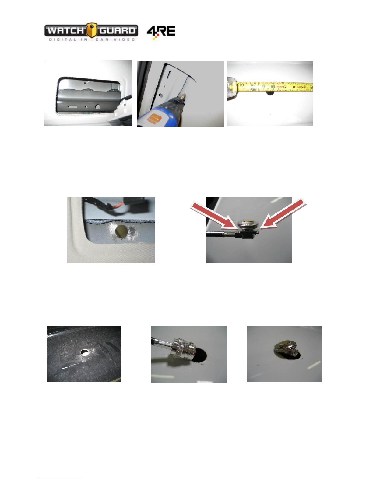
Mounting the Wireless Antenna to the Vehicle ................................................................................... 7
Mounting the Bullet Radio.......................................................................................................................... 10
Connecting the Power Cable to the Vehicle Battery ..................................................................................11
Connecting the External Inputs Cable......................................................................................................... 15
Ignition –White Wire.......................................................................................................................... 15
Emergency Lights –Blue with White Stripe........................................................................................16
Siren –Pink and Green Wires ............................................................................................................. 17
Auxiliary –Solid Blue Wire .................................................................................................................. 18
Brake Input –Black Wire with White Stripe .......................................................................................19
Chassis Ground –Yellow Wire ............................................................................................................20
Power Over Ethernet (PoE) Adapter –Orange and Brown.................................................................21
PoE Ethernet Cable Connections ................................................................................................................21
MDC/MDT Configuration (Optional)...........................................................................................................22
PoE Switch................................................................................................................................................... 22
Radar Interface Cable (Optional) –Purple/Black/Gray connector .............................................................23
GPS Antenna (Optional)..............................................................................................................................23
Display and Front Combo Camera –HDMI/HDMI mini .............................................................................. 23
Front HD camera HDMI/HDMI mini............................................................................................................ 23
Rear analog camera HDMI/BNC and molex power.....................................................................................23
Mounting the Remote Display Control Panel ............................................................................................. 24
Wireless Microphone.................................................................................................................................. 24
Cabin Microphone.......................................................................................................................................25
Front HD Combination Camera...................................................................................................................27
Test Functions of DVR ................................................................................................................................. 30

Vehicle Installation Instructions
WGD00085 REV B1 Page 3
Standard Parts included for a wireless installation
Qty
Part Number
Description
1
WGA00480-100
4RE, HD DVR, (2nd Generation)
1
WGA00370
4RE, Remote Display Control Panel
1
WGA00437
Camera Assembly, 4RE, HD Front, Glass mount
1
WGP01760-100
Camera, Infrared Analog, WMv.1, 2-Pin Connector
1
WGA00475-KIT
Hi-Fi Microphone Kit
Transmitter
Cradle
10 ‘Antenna Cable
Clips
1
WGA00428-001
4RE In-Car 802.11n Wireless Kit (Bullet, Antenna, PoE)
1
WGP01475
Bracket, HiFi Microphone, Universal
1
WGP01443-001-KIT
Bracket Kit, 4RE, DVR, Universal
1
WGA00420
Bracket Kit, 4RE, Display, Standard RAM 2"
1
WGP362
GPS Antenna, Magnetic Mount
1
WGD00085-KIT
Kit, 4RE DVR Installation Kit, Wireless
1
WGD00089-KIT
Kit, 4RE In-Car Video System User Guide
1
WGP01394-001
Wi-Fi Vehicle Antenna Mount, NMO, Drill 3/4" Hole,
1
WGP01506-KIT
Cable Assembly, DV-1C/4RE, Power/Input, R/A, 24'
1
WGP412
Cabin Microphone - 7'
1
WGP412-300
Cabin Microphone Extension Cable - 12'
1
WGP01832
4RE, Cable, HDMI, Port 2, Backseat Camera, 16’
1
WGP01829-004
4RE, Cable, HDMI, Front Cam, Straight, 15'
1
WGA00382
4RE, Cable, HDMI, Display/Combo Cam, Straight, 15'
Optional parts for installation
Qty
Part Number
Description
1
WGA480-600
4RE, HD DVR & Mezzanine, (2nd Generation)
1
WGA00475-CHARGEKIT
Hi-Fi Microphone Desktop Charger Kit 1
1
WGP01507-004
4RE, Cable, HDMI, Display/Combo Cam, R/A, 15'
1
WGP01829-004
4RE, Cable, HDMI, Front Cam, Straight, 15'
1
WGP01688
4RE, Cable, Mezzanine, VGA to 4-Analog Cam, 7'
1
WGP01803
4RE, Cable, HDMI, Port 2, Backseat Camera, 2-Pin 16'
1
WGA00348
Camera Assembly, 4RE, HD Front/Cabin Combo, Glass Mount
1
WGA00391
4RE, Power Over Ethernet / Gigabit 4-port Switch
1
WGA00351-200
Dual Microphone Splitter, 3-Port, HiFi Mic and Trinus
1
N/A
4RE Display Bracket (varies on model of vehicle)
1
WGP01487-KIT
Bracket Kit, 4RE, DVR, Console Faceplate, 2"

Vehicle Installation Instructions
WGD00085 REV B1 Page 4
Recommended Tools
Drill and bits
o¾ inch bit for antenna mounting
oPhilips bits
Coarse sandpaper 60 or 80 Grain
10-30 feet of 16-20 gauge primary wire for extending input cable connections if necessary
Wire strippers
Wire cutters
Various wrenches and sockets (one unusual open ended wrench needed is 24mm or 15/16’’)
Pliers
Utility Knife
Torx screwdrivers or bits sizes T20, T15, T10
1/16” hex screwdriver or Allen head wrench
Electrical Tape and/or heat shrink tubing
Zip ties
Document Conventions:
The following conventions are used within this document.
Note: Notices provide useful supplemental information that is pertinent to the task or item being
described.
Caution: Cautions describe very important information that, if ignored, could result in damage to the
system, inoperability or degradation in function, or injury to personnel.
Warning: Warnings describe critical information that should not be ignored.

Vehicle Installation Instructions
WGD00085 REV B1 Page 5
Before installing the 4RE system in a vehicle
Begin by ensuring that you have received all the parts for the 4RE system. If you have any missing or
damaged parts please call WatchGuard Video Customer Service at 1-866-384-8567.
1. Ensure that the mounting brackets for the DVR, display screen, and wireless microphone bracket
are the correct types for your specific vehicle(s).
2. Gather all necessary tools for the installation.
3. Use the 4RE installation poster as a reference guide for the overview of the installation
a. If you did not receive an installation poster, you can download a copy from our website:
http://watchguardvideo.com/support/ or call 1-866-384-8567.
4. Determine if any of the cable lengths will be too short. If a cable is too short please contact
customer service for a different cable length.
5. Prepare the vehicle for installation.
a. Remove any old video equipment (if applicable)
b. Determine installation locations for the 4RE DVR, Bullet wireless radio, wireless
antenna, GPS antenna, etc.
c. Determine all wire connection points before starting the installation, i.e. vehicle battery
location, overhead input, brake input, auxiliary input, etc.

Vehicle Installation Instructions
WGD00085 REV B1 Page 6
Quick Overview of Installation
1. Gather all tools and materials
2. Mount Radio antenna and route cable
3. Configure and mount Radio Bullet
4. Install external inputs/power cable
5. Route cables for:
a. Camera(s)
b. Wireless Microphone
c. Cabin Microphone
d. Touch display
e. Ethernet
6. Install optional cables (GPS and Radar)
7. Install optional switch for MDC/MDT application
8. Mount PoE connector
9. Mount touch display bracket
10. Mount Wireless Microphone
11. Connect and mount camera(s)
12. Connect cables to DVR
13. Insert fuse
14. Turn on DVR and test functions (Also see Quick Reference Guide to test functions)
Note: If using a Mezzanine card (additional ports) the “WIRELESS MIC 2” and “AUX MIC” ports are not
used. The firmware does not activate these ports. Instead use the Dual Mic splitter.

Vehicle Installation Instructions
WGD00085 REV B1 Page 7
Starting Your Installation:
Mounting the Wireless Antenna to the Vehicle
Find a suitable location for the antenna and a route for the antenna cable. Typically the antenna is
mounted on the roof or trunk of the vehicle. The antenna cable is then routed to where the Wireless
Radio will be placed. WatchGuard Video recommends that you configure the Wireless Radio before
mounting it into the vehicle.
Caution: There are 2 different types of antenna mounts –a thru-hole antenna (NMO mount) which
requires drilling a ¾” hole in the metal of the vehicle OR a magnetic mount which does not require
drilling a hole. WatchGuard Video recommends using the NMO mount antenna if possible for better
signal strength.
Determine where you will mount the antenna. The following installation example demonstrates
mounting procedure in a Chevrolet Tahoe Police Package Vehicle. If you have a different vehicle the
installation may vary.
1. You can access the roof of the vehicle through a rear seat dome light or by removing the
headliner. [Figure 1 and 2]
Figure 1 Figure 2

Vehicle Installation Instructions
WGD00085 REV B1 Page 8
2. Drill a ¾ inch hole for the antenna cable. [Figure 5]
Figure 3 Figure 4 Figure 5
3. After the hole is made, sand the paint off the interior metal around the hole to ensure a good
ground. [Figure 6]
4. Remove the NMO exterior nut.
5. Ensure that the antenna mount ridges come in contact with the bare metal. [Figure 7]
Figure 6 Figure 7
6. Feed the antenna cable connector end first through the ¾ inch exterior hole in the roof of the
vehicle. [Figure 8 and 9]
7. Tilt the antenna mount and guide it into the hole and center the flange in the drilled hole.
[Figure 10]
Figure 8 Figure 9 Figure 10

Vehicle Installation Instructions
WGD00085 REV B1 Page 9
8. Re-attach the NMO nut with the o-ring facing down to create a seal. [Figure 11]
9. Tighten the nut with a 24mm or 15/16’’ open end wrench ensuring that the mount stays
centered in the hole and that the mount does not turn and kink the cable. [Figure 12]
Warning: Do not use a Channel lock pliers as it could damage the NMO nut. Instead use an
open end wrench. Damaging the NMO nut could result in unreliable wireless signal.
Figure 11 Figure 12 Figure 13
10. Route the antenna connector to where the Bullet radio will be mounted –make sure to leave
enough slack to avoid kinks.
11. Attach the antenna connector to the Bullet radio. [Figure 14]
Figure 14
Warning: Never plug in the PoE connector (Ethernet connection) and power up the Bullet radio
without an antenna attached as it can damage the radio.

Vehicle Installation Instructions
WGD00085 REV B1 Page 10
Mounting the Bullet Radio
For Instructions on how to configure the Bullet with the wireless network see the document:
Evidence Library Administrative Guide
Warning: In order to configure the Bullet it must be attached to a POE power adapter and the
antenna before connecting to your computer. Make sure you attach your Ethernet cable from
your laptop to the port on the POE adapter labeled “DVR” or you may damage your laptop.
The Bullet should be mounted in a way that the LED lights can be easily viewed for diagnostic purposes.
Common mounting locations are:
Glove compartment
On the front of the Cage
Inside the center console
There is no mounting hardware included with the Bullet radio. It is typical to use zip ties to attach the
radio to your desired location.
To see if the Bullet is working properly, check the LED lights on the side of the device.
1. Power LED: The power LED will be lit, if the Bullet has power.
2. Connectivity LED: This light will blink if it is communicating with the DVR
3. Signal LED’s: These 4 LED’s will light up if the Bullet is “Associated” with the Access
Point. In most cases the vehicle will not be near the Access Point during the time of
installation. Red is low signal, and each LED to the right is a better strength.
To verify the Bullet is connected properly, see Page 29.

Vehicle Installation Instructions
WGD00085 REV B1 Page 11
Connecting the Power Cable to the Vehicle Battery
The power/external inputs cable looks like the following:
Figure 15
1. Route the power cable to the vehicle battery.
Note: For the Chevrolet Tahoe with a dual battery configuration, use the passenger side battery if
possible. The passenger battery is considered an auxiliary battery for electronics.
2. When routing the power cable, use factory firewall holes and grommets if possible.
There are usually several factory firewall ports giving access to the engine bay. Use the one that is the
easiest to access.
Ford Crown Victoria –factory grommet is on the front foot-well on the passenger side.
Dodge Charger –battery is located in the trunk. The power cable can be routed down the passenger
side rail and under the rear seat in the factory wiring channel that runs back to the battery.
Chevrolet Impala –use the driver door grommet and go through to the inside of the fender to the front
of the engine bay.
Chevrolet Tahoe –the following example is from a Chevrolet Tahoe –a small grommet hole is behind
the factory fuse block located on the driver’s side foot-well. Remove the rubber gasket, slit a small hole
in the grommet and pass the power cable through to the engine bay. [Figure 16]

Vehicle Installation Instructions
WGD00085 REV B1 Page 12
Figure 16 Figure 17
3. Pull the power cable to the battery.
4. Pull excess cable out past the battery side of the firewall (leave some slack for a drip loop).
Figure 18
5. Also pull the Chassis ground extension wire to the vehicle battery at this time, if possible. It is
easier to route the chassis ground cable with the rest of the cables. (The extension cable is not
included, use an additional cable for this function)
6. You can either wind up and tie off the excess cable or cut off the excess cable where necessary.
7. Strip / remove approximately 3-5” of the external black sheathing and the foil Mylar shielding
from the power cable.
Grommet access
through firewall

Vehicle Installation Instructions
WGD00085 REV B1 Page 13
8. Strip back ½ inch on the red, black and additional Chassis ground cable. [Figure 19]
Figure 19
9. Twist the black ground, the un-insulated silver drain wire, and chassis ground wires together
[Figure 20] and crimp on a ring terminal to be attached to the battery negative ground post.
[Figure 21]
Figure 20 Figure 21
10. Crimp the red positive wire to the inline fuse holder using a butt-splice connector and a ring
terminal to the end of the inline fuse holder to be attached to the positive battery post.
[Figure 22]
Figure 22

Vehicle Installation Instructions
WGD00085 REV B1 Page 14
11. Connect the positive and negative wires to the appropriate vehicle battery posts. [Figure 23]
Figure 23
12. Route the power harness inside the engine bay in such a manner that it will not interfere with
the vehicle.
Note: Leave the 7.5 amp fuse out until the DVR is ready to be turned on.
Positive (+) side

Vehicle Installation Instructions
WGD00085 REV B1 Page 15
Connecting the External Inputs Cable
Before connecting the input cable it is necessary to know the wiring scheme for connecting the external
inputs cable. All the inputs generally require positive 8-12 volts of power to activate the corresponding
device. When a particular input senses a positive voltage on its wire, the selected input will turn on or
become active.
Connect the wires from the input cable using butt splices where possible. This ensures a good
connection and consistent voltage.
Ignition –White Wire
The ignition wire senses whether the ignition is on or off. The white wire needs to connect to a feed
that provides positive 12 volts when the vehicle is ON and 0 volts when the vehicle is OFF. There is a
fuse link with a 1 amp fuse provided to connect the ignition feed and the ignition sense wire from the
inputs cable. [Figure 24]
Several common factory sources for ignition power are as follows:
Crown Victoria –pink wire inside the gray rectangular police package wiring harness located under the
passenger side dashboard.
Dodge Charger –pink wire with purple stripe inside the white rectangular police package wiring harness
inside the center console.
Chevrolet Impala –pink or yellow wire in the factory police package wiring harness located under the
passenger side carpeting.
There are several options available for configuring how the system reacts to the vehicle ignition signal.
To change these configurations refer to the document: Evidence Library Administrator Guide.
Figure 24

Vehicle Installation Instructions
WGD00085 REV B1 Page 16
Emergency Lights –Blue with White Stripe
The Emergency Lights input should connect to a positive 12 volt switched power source that provides
voltage when the overhead lights are activated. [Figure 25]
Note: Some emergency light manufacturers use negative 12 volt or ground triggers. In those cases an
additional relay may need to be incorporated into the wiring scheme to provide positive 12 volt power
to the input wire.
Figure 25

Vehicle Installation Instructions
WGD00085 REV B1 Page 17
Siren –Pink and Green Wires
The siren input wire consists of two wire connections –the green wire is connected to the siren speaker
ground feed and the pink wire is connected to the positive siren speaker feed. When the siren is
activated then the siren input will sense voltage. [Figure 26]
Figure 26

Vehicle Installation Instructions
WGD00085 REV B1 Page 18
Auxiliary –Solid Blue Wire
Depending on the installation this input wire may or may not be used. The input should be connected to
a device that provides positive 12 volt switched power to be used as an alternate trigger. For example,
the input can be connected to a shotgun mount electric release button or a K-9 electric kennel door
release. [Figure 27]
Figure 27

Vehicle Installation Instructions
WGD00085 REV B1 Page 19
Brake Input –Black Wire with White Stripe
The brake input should connect to a positive 12 volt switched power activated when the brake pedal is
depressed. When the brakes are pressed, the wire should get 12 volts. Depending on the installation
this wire may or may not be used. This is a useful input for an administrator to see if an officer was
pressing the brake before a crash. [Figure 28]
Several common factory sources for brake light power are as follows:
Crown Victoria –Green wire with red stripe located on the brake pedal switch.
Dodge Charger –Brown with purple stripe wire inside the large rectangular gray police package wiring
harness inside the center console (Note: only provides 7-8 volts)
Chevrolet Impala –Green wire marked 6J6 on the harness in the factory police package wiring harness
located under the passenger side carpeting.
Figure 28

Vehicle Installation Instructions
WGD00085 REV B1 Page 20
Chassis Ground –Yellow Wire
It is imperative that the chassis ground wire is grounded properly. The DVR is sensitive to ground loops
and any stray voltage that may be running through the frame ground of the vehicle. Ensure that the
chassis ground is connected to a good bare metal ground lug or bare metal screw/nut/bolt. Test the
wire with a volt meter (or multi-meter) and ensure there is no stray voltage. The Chassis Ground cable
should not have any more than +/- .025 volts. Anything more will cause the DVR to be unpredictable
is operation. In Figure 29 the voltage reading is TOO HIGH.
Figure 29
Warning: Improperly grounded chassis ground wire connections will result in unpredictable DVR
operation and performance.
Note: WatchGuard Video recommends that the Chassis ground always be grounded to the
Negative (ground) post on the vehicle battery.
External Ground
Chassis Ground
Other manuals for 4RE
2
Table of contents
Other Watchguard Car Video System manuals
Popular Car Video System manuals by other brands

Sony
Sony DVX-11A - Car Mp3/dvd/cd Single Player Installation/connections

Sony
Sony XAV-C1 operating instructions

Car Solutions
Car Solutions HD-LINK IW04VW instruction manual

Eonon
Eonon E3015m instruction manual

InCarTec
InCarTec 27-550 instruction manual

Insignia
Insignia NS-D9500 - Mobile DVD Player user guide