Water Furnace Aurora User manual
Integrated Aurora Controls for Versatec 700 Indoor DOAS Applications
INTEGRATED COMMERCIAL AURORA CONTROLS FOR VERSATEC
700 INDOOR DOAS APPLICATIONS
ICM2701EW 01/22


INTEGRATED COMMERCIAL AURORA CONTROLS FOR VERSATEC 700 INDOOR DOAS APPLICATIONS
Table of Contents
Table of Contents
Overview & Features . . . . . . . . . . . . . . . . . . . . . . . . . . . . . . . . . . . . . . . . . . . . . . . . . . . . . . . . . . . . . . . . . . . . . . . 4
Applications. . . . . . . . . . . . . . . . . . . . . . . . . . . . . . . . . . . . . . . . . . . . . . . . . . . . . . . . . . . . . . . . . . . . . . . . . . . . . . . .5
Aurora Energy Controls Packages . . . . . . . . . . . . . . . . . . . . . . . . . . . . . . . . . . . . . . . . . . . . . . . . . . . . . . . . . . . .6
Safety Features . . . . . . . . . . . . . . . . . . . . . . . . . . . . . . . . . . . . . . . . . . . . . . . . . . . . . . . . . . . . . . . . . . . . . . . . . . . . .7
Layout . . . . . . . . . . . . . . . . . . . . . . . . . . . . . . . . . . . . . . . . . . . . . . . . . . . . . . . . . . . . . . . . . . . . . . . . . . . . . . . . . . . . .8
Physical Data . . . . . . . . . . . . . . . . . . . . . . . . . . . . . . . . . . . . . . . . . . . . . . . . . . . . . . . . . . . . . . . . . . . . . . . . . . . . . .10
Control Inputs . . . . . . . . . . . . . . . . . . . . . . . . . . . . . . . . . . . . . . . . . . . . . . . . . . . . . . . . . . . . . . . . . . . . . . . . . . . . . 11
Control Outputs . . . . . . . . . . . . . . . . . . . . . . . . . . . . . . . . . . . . . . . . . . . . . . . . . . . . . . . . . . . . . . . . . . . . . . . . . . . 13
Configuration Settings. . . . . . . . . . . . . . . . . . . . . . . . . . . . . . . . . . . . . . . . . . . . . . . . . . . . . . . . . . . . . . . . . . . . . . 13
System Operation . . . . . . . . . . . . . . . . . . . . . . . . . . . . . . . . . . . . . . . . . . . . . . . . . . . . . . . . . . . . . . . . . . . . . . . . . . 15
Sensor Locations . . . . . . . . . . . . . . . . . . . . . . . . . . . . . . . . . . . . . . . . . . . . . . . . . . . . . . . . . . . . . . . . . . . . . . . . . . 21
4
INTEGRATED COMMERCIAL AURORA CONTROLS FOR VERSATEC 700 INDOOR DOAS APPLICATIONS
Overview & Features
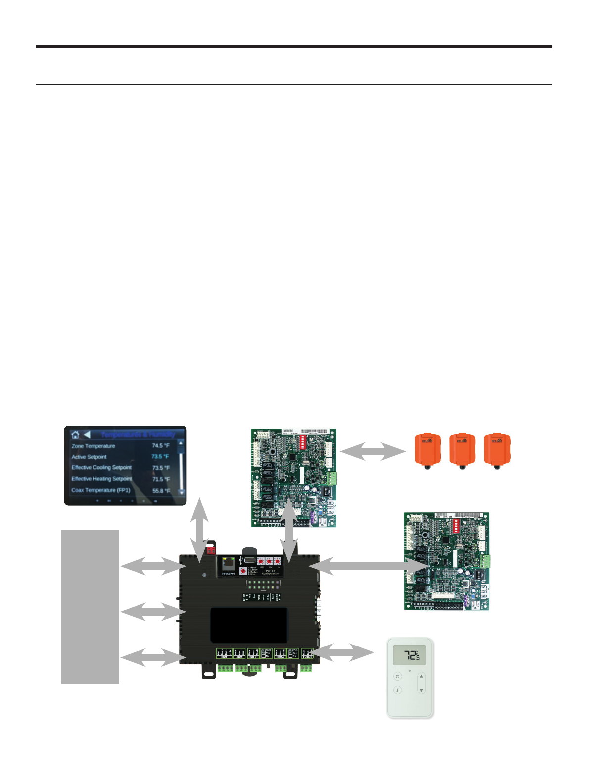
BACnet
ModBus
Stand-alone
BAS
Rnet
Modbus
Modbus
Modbus
AURORA SYSTEM
AURORA PREMIUM
ECONOMIZER & SENSORS
AURORA TOUCH HMI
AURORA
ENERGY
SENSORS
Ethernet
Integrated Controls Platform
The Versatec DOAS unit operates on the Aurora Controls Network (ACN) which brings together different technologies
such as variable speed compressors, direct drive ECM plenum fans, electronic expansion valves, CFM control, and total
energy recovery to provide a complete DOAS unit. The Versatec DOAS control platform consists of the Aurora System
controller, Aurora Energy Control (AEC), and Aurora Premium. The AEC is a complete microprocessor which functions
as the state engine management of the air-to-air energy recovery equipment. It controls the operation of the energy
wheel, bypass dampers, exhaust blowers, and reads any sensors that are enabled on the energy recovery unit. It also
provide safety features of the energy recovery unit. The Aurora Heat Pump control provides state engine management
for the variable speed heat pump system. It will communicate to the supply blower, inverter board, and other communi-
cating devices or sensors that are enabled on the heat pump. The Aurora DOAS controller is the application controller
that provides all the decision making for the DOAS unit, provides setpoints and overrides to the heat pump and energy
recovery units.
• Simplified diagnostics for the DOAS system with
intuitive large touch screen display with the Aurora
Touch Tablet2
• All sensors communicate over modbus and are
reportable to the BAS
• Full Integration with Aurora Controls Network
• Hot gas modulating reheat with head pressure control
• Preheat output signal with configurable outdoor air
temperature limits
• Economizer operation with factory installed outdoor
air and exhaust air bypass dampers.
• Intelligent sensors at each station on the air-to-air
energy recovery device.
• CFM control
• Advanced Dehumidification
• Multi-Zone VAV
• Single Zone VAV
• CAV
• Demand controlled ventilation
• Drybulb/Enthalpy controlled economizer operation
• Supply Air Temperature Reset
• Remote Supply Air Temperature Reset
• Aurora DOAS Controller Secondary Operation
• Building Pressure Control
• BACnet MS/TP and IP capable
• Network controlled CFM

5
INTEGRATED COMMERCIAL AURORA CONTROLS FOR VERSATEC 700 INDOOR DOAS APPLICATIONS
DOAS Applications
100% Outdoor Air
The Versatec DOAS unit is designed to fit a
range of variable air volume (VAV) applica-
tions such as single-zone VAV, multi-zone VAV,
and constant air volume (CAV).
Single-Zone VAV
Single-zone VAV systems have typically been
used in larger zones with higher populated areas
with variable cooling loads such as churches,
meeting rooms, gymnasiums, etc. Single-zone
VAV combines aspects of multi-zone VAV and
constant air volume (CAV) applications to serve a single-
zone/space by using temperature setpoints to enable cooling/heating/dehumidification
mode. This application does not contain VAV boxes and the supply blower will operate to maintain the space temperature
in the zone.
Multi-Zone VAV
For multi-zone applications, the controller is configured to control the supply fan to maintain a duct static pressure setpoint.
The variable speed compressor will operate to either a leaving air temperature or evaporator coil temperature in cases where
the unit is equipped with modulating hot gas reheat. In cases with modulating hot gas reheat, the reheat valve will operate
off of a PID that controls to a leaving air temperature setpoint.
Multi-zone VAV units can be applied in a variety of ways such as operating off of BACnet from a BAS controller or stand-alone
operation with or without a thermostat
Constant Air Volume (CAV)
By adjusting the duct static pressure setpoint in the Aurora Premium control to constant, it can turn the VAV controller into
a CAV control application. With the exception of the blower modulation, the system will control the compressor to a leaving
air temperature and operate with all of the same input configuration points.
Model Shown: DAS360
Multi-zone VAV application for office building
6
INTEGRATED COMMERCIAL AURORA CONTROLS FOR VERSATEC 700 INDOOR DOAS APPLICATIONS
Each Versatec DOAS unit comes with optional controls packages that are included in the energy recovery device which is
represented by the Aurora Energy Controls. These packages are detailed below. Airside economizer functionality can be
added to any of the packages below by adding air bypass dampers.
Aurora Base Energy (“N”)
The Aurora Base Energy is the standard controls package that includes the necessary sensors on the energy recovery
device for DOAS operation. These sensors are listed below.
Aurora Advanced Energy (“P”)
The Aurora Advanced Energy adds additional features to the Aurora Base Energy as described below.
Aurora Premium Energy (“Q”)
The Aurora Premium adds more sensors to the Aurora Advanced as described below.
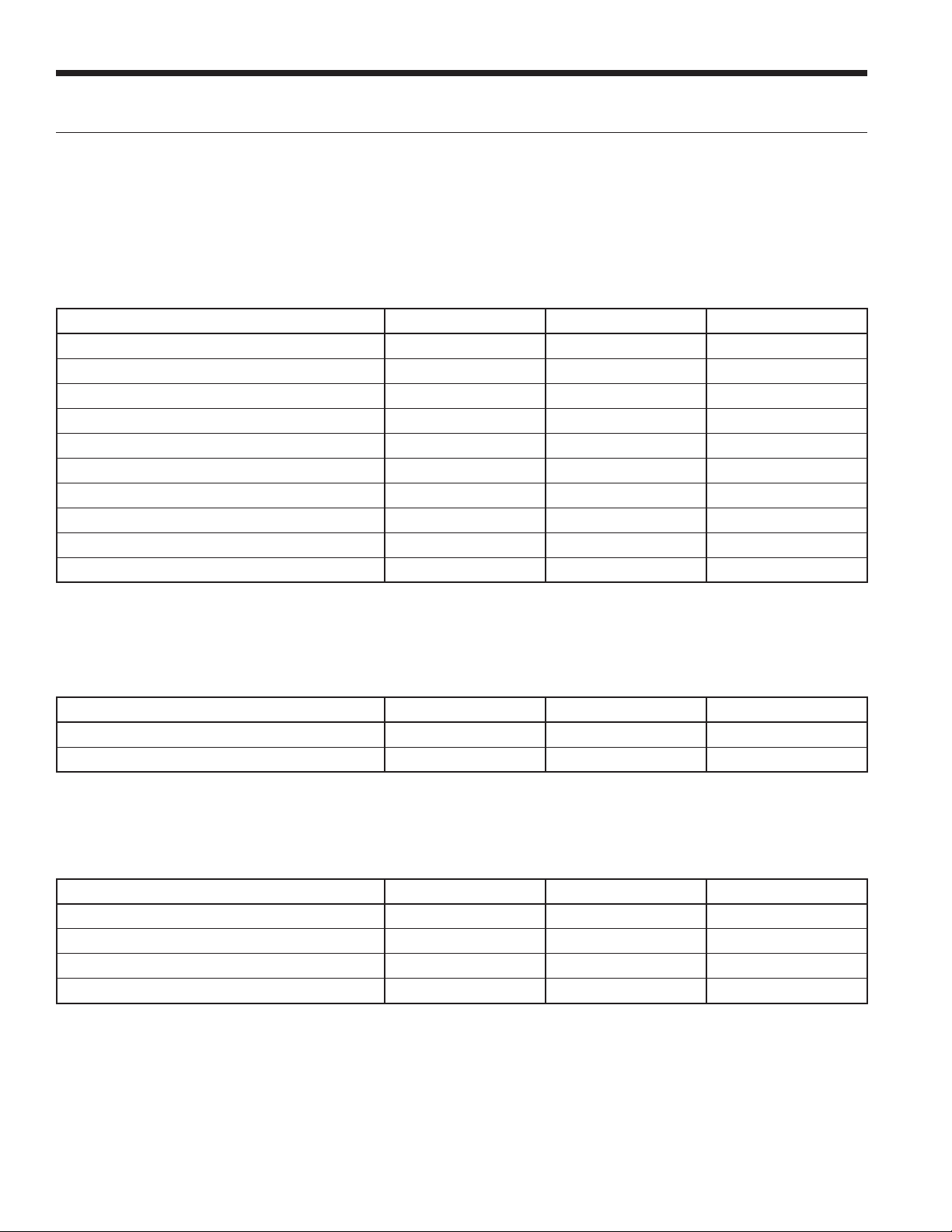
Aurora Energy Control Packages
Description Type ERW FAV
Outdoor Air Enthalpy Sensor AEC/Modbus X
Return Air Enthalpy Sensor AEC/Modbus X
Entering Wheel Temperature AEC/Analog X
Leaving Wheel Temperature AEC/Analog X
Building Static Pressure Variable BAS Network variable
Demand Controlled Ventilation BAS Network variable
Supply Blower CFM Measurement X
Exhaust Blower CFM Measurement X
Preheat Output Signal AEC/24 VAC
Supply Air Temperature Sensor Field Installed RNet
Description Type ERW FAV
Exhaust Air Enthalpy Sensor AEC/Modbus X
Optical Wheel Rotation Sensor AEC/Analog X
Description Type ERW FAV
Exhaust Filter Differential Pressure AEC/Modbus X
CO2 Return Air Sensor AEC/Modbus X
Wheel Differential Pressure AEC/Modbus X
Supply Filter Differential Pressure AEC/Modbus X

7
INTEGRATED COMMERCIAL AURORA CONTROLS FOR VERSATEC 700 INDOOR DOAS APPLICATIONS
Safety Features
The following safety features are provided to protect the
energy recovery device, wiring, and other components from
damage caused by operation outside of design conditions.
Fuse – A 3 amp automotive type plug-in fuse provides
protection against short circuit or overload conditions.
Over/under voltage – An over/under voltage condition
exists when the control voltage is outside the range of 18
VAC to 30 VAC.
Low OAT shutdown – Low OAT shutdown will de-activate
all outputs based on a the Low OAT threshold temperature.
This is a configured setting to prevent operation in
undesirable conditions.

8
INTEGRATED COMMERCIAL AURORA CONTROLS FOR VERSATEC 700 INDOOR DOAS APPLICATIONS
Layout - Aurora Premium (ERW Cabinet)
Layout - Aurora System Controller & AEC (ERW Cabinet)
Aurora Touch HMI
Aurora Energy Control (AEC)Aurora System Controller & AEC (ERW
Cabinet)

9
INTEGRATED COMMERCIAL AURORA CONTROLS FOR VERSATEC 700 INDOOR DOAS APPLICATIONS
Layout - Aurora Premium (FAV Heat Pump Controls)
CC2
Factory
Fault
ALG
ALM
LS
ES
ACC c
Status
AuroraTM Base
Control
RV – K1
CC2
CC – K2
CC Hi – K3
Fan – K4
Alarm – K5
Acc – K6
ACC no
ACC nc
O/B
C
R
LO
G
Y1
Y2
W
DH
3A-Fuse
O/B
C
R
LO
G
Y1
Y2
W
DH
LO
G
HI
CCG
CC
FG
F
R
HP
HP
LP
FP2
FP2
FP1
REV
REV
CFM
PWM
ECM PWM
Factory
Factory Fan Connection
RR
CC
C
C
R
(-)
(+)
RS 485
EH2
C
EH1
C
CO
(+)
(-)
R
C
RS485
Exp Factory
Com1
Com2
Config
G
G
G
YR
SW1 Test
FP1 – 15oF/30oF
JW2 - Alarm
P11
P5
P2 P1
P8
P7
P9
P6
P3
SW2
P13
P4 FP2 – 15oF/30oF
RV – B/O
ACC
– Dip
1
ACC
– Dip
2
CC – Dual/Single
L – Pulse/Continuous
Reheat/Normal
Factory Use
Field ConnectionsField Connections
C
LP
FP1
F
CC
G
Y1
1
2
3
4
5
6
7
8
Off On
N/A
RS485 NET
EH1
LED 1
LED 3
LED 2
LED 5
LED 4
SCT SUC P
HW
HW
MOTOR
RS485
P7
ZONE
P9
ABC
STEPPER ANA SPR DH DIV
NO
COM
K6
NO
COM
K5
C
R
L1
L1
L2
L2
P12 P10 P5 P11
C
R
(-)
(+)
C
R
(-)
(+)
C
R
(-)
(+)
P4 P2
K1
K2K3
HA2 HA1 SGI LOOP PWM VS SLO SLI
P3
V+
C
R
TX
RX
+5
P14
LLT
P1 LATFLOWLWTEWT
CT2
4 3
CT2
4 3
CT1
2 1
CT1
2 1
Status
G
DISCH
P16
P17 P18 P15
(Aurora Expansion Board)
AXB™
See Figure 1 for
DHW wiring.
SW1
Modbus Add. ID
Future Use
1
2
3
4
5
ONOFF
Future Use
Acc 2 – Dip 4
Acc 2 – Dip 5
P8 P6
ABC Control Board Layout AXB Control Board Layout
Compressor Drive
CC2
EH1
Fac t ory
Faul t
ALG
ALM
LS
ES
ACC c
Status
AURORA BASE
CONTROL™
RV – K1
CC2
CC – K2
CC Hi – K3
Fan – K4
Alarm – K5
Acc – K6
ACC no
ACC nc
O/B
C
R
LO
G
Y1
Y2
W
DH
3A-Fuse
O/B
C
R
LO
G
Y1
Y2
W
DH
LO
G
HI
CCG
CC
FG
F
R
HP
HP
LP
FP2
FP2
FP1
REV
REV
CFM
PWM
ECM PWM
Fac t ory
Factory Fan Connection
RR
CC
C
RS 485
EH2
C
EH1
C
CO
(+)
(-)
R
C
RS485 Exp Fac t ory
Com1
Com2
Config
G
G
G
YR
SW1 Test
FP1 – 15oF/30oF
JW2 -
Alarm
P11
P5
P2 P1
P8
P7
P9
P6
P3
SW2
P13
P4 FP2 – 15oF/30oF
RV – B/O
ACC – Dip 4
ACC – Dip 5
CC – Dual/Single
L – Pulse/Continuous
Reheat/Normal
Factory Use
Fi eld ConnectionsFi eld Connections
C
LP
FP1
F
CC
G
Y1
1
2
3
4
5
6
7
8
Of f On
N/A
RS485 NET
LED3
LED2LED1
11111
33322
222
444
KM7
KM4 KM5 KM6 KM1
KM2
KM9
EEV/Power Supply Board Layout

10
INTEGRATED COMMERCIAL AURORA CONTROLS FOR VERSATEC 700 INDOOR DOAS APPLICATIONS
Physical Data
Serial Number
If you need the Aurora System controller (LS-CPU) serial number when troubleshooting, the number is on:
• a sticker on the back of the main translator board
• a Module Status report (modstat) from WebCTRL , or thru the Aurora Touch Interface by accessing the “Module Setup”
menu.
FCC Compliance
This equipment has been tested and found to comply with the limits for a Class A digital device, pursuant to Part 15 of the
FCC Rules. These limits are designed to provide reasonable protection against harmful interference when the equipment is
operated in a commercial environment. This equipment generates, uses, and can radiate radio frequency energy and, if not
installed and used in accordance with the instruction manual, may cause harmful interference to radio communications.
Operation of this equipment in a residential area is likely to cause harmful interference in which case the user will be
required to correct the interference at his own expense.
CAUTION: Changes or modifications not expressly approved by the responsible party for compliance could void the
user’s authority to operate the equipment.
CE Compliance
The Aurora UPC conforms to the following standards. A full Declaration of Conformity is available on request.
Electromagnetic Emissions: EN55022: 1994 Class A Electromagnetic Compatibility:
Immunity for Commercial Environments EN61000-6-1: 2007 Electrostatic Discharge: EN61000-4-2: 2008
Radiated Electromagnetic Field: EN61000-4-3: 2010 Electronic Fast Transient/
Burst Requirements: EN6100-4-4: 2004
Surge Immunity: EN6100-4-5: 2005 Immunity to Conductive Disturbance:
EN6100-4-6: 2008 Power Frequency Magnetic Field Immunity:
EN6100-4-8: 2009 Immunity to Voltage Dips and Variations
EN6100-4-11: 2004 European Low Voltage Directive
Restriction of the Use of Certain Hazardous Substances (RoHS)
BACnet Compliance
BACnet® is a registered trademark of ASHRAE. ASHRAE does not endorse, approve or test products for compliance with
ASHRAE standards. Compliance of listed products to requirements of ASHRAE Standard 135 is the responsibility of the
BACnet manufacturers Association (BMA). BTL certification is pending.
BTL® is a registered trademark of the BMA.

11
INTEGRATED COMMERCIAL AURORA CONTROLS FOR VERSATEC 700 INDOOR DOAS APPLICATIONS
Control Inputs
Direct AEC Inputs:
Leaving Wheel Temperature – The Leaving Wheel Tem-
perature sensor will be a 10kΩNTC thermistor connected to
the FP1 input on the AEC control.
Entering Wheel Temperature – The Entering Wheel Tem-
perature sensor will be a 10kΩNTC thermistor connected to
the FP2 input on the AEC control.
Optical Wheel Sensor – The Optical Wheel Sensor input
will be connected to the LPS input on the AEC control.
Shutdown – The Shutdown input will be a grounded signal
connected to the ES input on the AEC control. The opera-
tion of the Shutdown input will depend on the position of
AEC DIP switch SW6.
Supply Dirty Filter Switch – The Supply Dirty Filter Switch
(SDFS) input will be a 24 VAC input signal connected to
the W input on the AEC control. This switch is optional and
available upon request.
Exhaust Dirty Filter Switch – The Exhaust Dirty Filter
Switch (EDFS) input will be a 24 VAC input signal con-
nected to the DH input on the AEC control. This switch is
optional and available upon request.
Modbus Sensor Inputs:
For all Modbus devices, the device must be “added” to
the AEC Modbus slave device list for the AEC to attempt
communications with the device.
Outdoor Air Sensor – The Outdoor Air Sensor can provide
temperature, humidity, and enthalpy values.
Return Air Sensor – The Return Air Sensor can provide
temperature, humidity, and enthalpy values.
Exhaust Air Sensor – The Exhaust Air Sensor can provide
temperature, humidity, and enthalpy values. The Exhaust
Air Sensor is an optional sensor.
CO2 Return Air Sensor – The CO2 Return Air Sensor can
provide temperature, humidity, enthalpy, and CO2 values.
The optional CO2 Return Air Sensor replaces the standard
Return Air Sensor when present.
Exhaust Blower Differential Pressure –The Exhaust Blower
Differential Pressure Sensor can provide differential
pressure and volumetric flow values.
Building Differential Pressure – The Building Differential
Pressure Sensor can provide a signed differential pressure
value. The Building Differential Pressure Sensor is an
optional sensor.
Wheel Differential Pressure – The Wheel Differential
Pressure Sensor can provide a signed differential pressure
value. The Wheel Differential Pressure Sensor is an optional
sensor.
Supply Filter Differential Pressure – The Supply Filter
Differential Sensor can provide a signed differential
pressure value. The Supply Filter Differential Pressure
Sensor is an optional sensor.
Exhaust Filter Differential Pressure – The Exhaust
Filter Differential Pressure Sensor can provide a signed
differential pressure value. The Exhaust Filter Differential
Pressure Sensor is an optional sensor.
AEC Control DIP Switch Inputs
SW1 – System Configuration SW1 Future use
SW2 – System Configuration SW2 Future use
SW3 – Conditioning Inputs SW3 Future use
SW4 – ACC Relay Operation SW4 On = Track Blower,
SW4 Off = Track Wheel
SW5 – ACC Relay Operation SW5 Future Use
SW6 – Shutdown SW6 On = Emergency
Shutdown, SW6 Off =
Shutdown with Exhaust
SW7 – Alarm Output SW7 On = Continuous,
SW7 Off = Pulsed
SW8 – Future SW8 Future Use
All control system input values may be read from sensors physically connected to the control system, either communicating
or discrete, or they may be alternatively supplied via Modbus from a BAS controller or other appropriate Modbus master
controller.

12
INTEGRATED COMMERCIAL AURORA CONTROLS FOR VERSATEC 700 INDOOR DOAS APPLICATIONS
Control Outputs
Discrete AEC Outputs:
Outdoor Air Damper – The Outdoor Air Damper output
will be a 24 VAC output signal connected to the RV output
on the AEC control.
Energy Recovery Wheel – The Energy Recovery Wheel
output will be a 24 VAC output signal connected to the F
output on the AEC control.
External Preheat – The External Preheat output will be a 24
VAC output signal connected to the CC output on the AEC
control.
Alarm Relay Output – The Alarm Relay output will be a 24
VAC or dry contact output connected to the ALM output of
the AEC control.
Lockout Output – The Lockout Output will be a nominal 24
VDC output signal connected to the LO output of the AEC.
The operation of the output will depend on the setting of
AEC DIP switch SW7.
Modbus Controlled Outputs:
For all Modbus devices, the device must be “added” to
the AEC Modbus slave device list for the AEC to attempt
communications with the device.
Exhaust Blower – The Exhaust Blower is a Modbus
controlled output for an ECM plenum blower. The AEC may
control either one or two exhaust blowers. If the system
has two exhaust blowers, they will always be operated at
the same speed.
Supply Air Bypass Damper – The optional Supply Air
Bypass Damper is a Modbus controlled output for a
modulating actuator. The AEC may control either one or
two supply air bypass dampers. If the system has two
supply air bypass dampers, both actuators will always be
operated to the same position.
Exhaust Air Bypass Damper – The optional Exhaust
Air Bypass Damper is a Modbus controlled output for a
modulating actuator. The AEC may control either one or
two exhaust air bypass dampers. If the system has two
exhaust air bypass dampers, both actuators will always be
operated to the same position.

13
INTEGRATED COMMERCIAL AURORA CONTROLS FOR VERSATEC 700 INDOOR DOAS APPLICATIONS
Configuration Settings
Configuration setting values will be stored in non-volatile
memory and may be adjusted using an Aurora Touch HMI
or through the BAS interface.
Neutral Air Target SAT (NeutTgt)
The Neutral Air Target SAT is the system target SAT with
no active heating or cooling demand. The NeutTgt value
will be in the range of 45°F to 75°F, with a default value of
65°F.
Heating Air Target SAT (HeatTgt)
The Heating Air Target SAT is the target SAT with active
heating demand. The HeatTgt value will be in the range of
65°F to 85°F, with a default value of 80°F.
Cooling Air Target SAT (CoolTgt)
The Cooling Air Target SAT is the target SAT with active
cooling demand. The CoolTgt value will be in the range of
45°F to 65°F, with a default value of 50°F.
Target Supply Air Humidity (SAHtgt)
The Target Supply Air Humidity is the target value for the
supply air relative humidity. The SAHtgt value will be in the
range of 50% to 75% RH, with a default value of 60% RH.
Deadband Temperature Value (DBT)
The Deadband Temperature Value is the temperature
hysteresis value for operational condition activation /
deactivation. The DBT value will be in the range of 0.5°F to
5.0°F with a default value of 2.0°F.
Deadband Humidity Value (DBH)
The Deadband Humidity Value is the humidity hysteresis
value for operational condition activation / deactivation.
The DBH value will be in the range of 1% to 5% with a
default value of 2%.
Deadband Enthalpy Value (DBE)
The Deadband Enthalpy Value is the enthalpy hysteresis
value for operational condition activation / deactivation.
The DBE value will be in the range of 0.1 BTU/lb. to 1.0
BTU/lb., with a default value of 0.3 BTU/lb.
Supply Blower Target (SupBlwTgt)
The Supply Blower Target value is the target nominal
supply blower operating CFM value. The SupBlwTgt
value range and default value will be dependent on the
configuration. The actual operating target CFM may
vary from the nominal setting under certain operating
conditions such as DCV.
Supply Airflow Calculation Multiplier
(kSCFM)
The Supply Airflow Calculation Multiplier value is used to
calculate the airflow for the supply blower based upon
the measured values from the differential pressure sensor.
Appropriate ranges and default values for the kSCFM value
are shown in the BlowConfig table above.
DCV Enable (DCV)
The DCV Enable value is a Boolean control point to enable
or disable demand control ventilation operation. The
default state will be disabled.
CO2 Target for DCV (DCVlimit)
The CO2 Target for DCV is the target level for demand
control ventilation operation. The DCVlimit will be in the
range of 300 ppm to 1500ppm with a default value of 900
ppm.
DCV interval Time (DCVint)
The DCV Interval Time is the time period between potential
adjustments of the supply blower based on the current
CO2 value for demand control ventilation operation. The
DCVint value will be in the range of 15 seconds to 60
seconds, with a default value of 30 seconds. This value
will most likely not be exposed for field modification, but
adjustable for development.
Building Pressurization (BldPres)
The Building Pressurization value is a Boolean control point
to enable or disable building pressurization operation. The
default state will be disabled.
Building Pressurization Target (BPDP)
The Building Pressurization Target value is the target
differential pressure for building pressurization operation.
The BPDP value will be in the range of –0.20 inchWC to
0.20 inchWC with a default value of 0.01 inchWC.
Preheat Temperature Limit (PHtemp)
The Preheat Temp Limit is the activation temperature below
which preheat is activated. The PHtemp value will be in the
range of –25°F to 30°F with a default value of 20°F..
Minimum Ventilation Temperature
(MinVent)
The Minimum Ventilation Temperature is the minimum
allowed ventilation air temperature without the wheel
operating. The MinVent temperature limit will be in the
range of 35°F to 55°F with a default value of 45°F.
Maximum Ventilation Temperature
(MaxVent)
The Maximum Ventilation Temperature is the maximum
allowed ventilation air temperature without the wheel
operating. The MaxVent temperature limit will be in the
range of 75°F to 95°F, with a default value of 85°F.
Absolute Minimum OAT (MinOAT)
The Absolute Minimum OAT is the minimum outdoor
temperature for operation of the system with or without
pre or post heat. The MinOAT will be in the range of –40°F
to 20°F, with a default value of 15°F.

14
INTEGRATED COMMERCIAL AURORA CONTROLS FOR VERSATEC 700 INDOOR DOAS APPLICATIONS
Configuration Settings cont.
Supply Filter Base DP (SFBaseDP)
The Supply Filter Base DP is the differential pressure
value of the Supply Filter Differential Pressure Sensor
with a clean filter. The value will be set at system start-up
by a technician with the system blower operating. The
SFBaseDP value will be in the range of 0.010 inchWC to
0.500 inchWC with a default value of 0.100 inchWC.
Exhaust Filter Base DP (EFBaseDP)
The Exhaust Filter Base DP is the differential pressure
value of the Exhaust Filter Differential Pressure Sensor
with a clean filter. The value will be set at system start-up
by a technician with the exhaust blower operating. The
EFBaseDP value will be in the range of 0.010 inchWC to
0.500 inchWC with a default value of 0.100 inchWC.
Wheel Base DP (WhBaseDP)
The Wheel Base DP is the differential pressure value of the
Wheel Differential Pressure Sensor with a clean wheel. The
value will be set at system start-up by a technician with the
system blowers operating. The WhBaseDP value will be in
the range of 0.010 inchWC to 1.000 inchWC with a default
value of 0.250 inchWC.

15
INTEGRATED COMMERCIAL AURORA CONTROLS FOR VERSATEC 700 INDOOR DOAS APPLICATIONS
System Operation - System Operating Modes
Energy Recovery Cooling
In the energy recovery cooling mode, the bypass dampers
will be closed, the energy wheel will be active, and the
compressors will operate as needed to maintain supply air
conditions.
Economizer
In the economizer mode, the bypass dampers will be open,
the energy wheel will be de-activated, and the compressors
will operate as needed to maintain supply air conditions.
Economizer with Energy Recovery
In the economizer with energy recovery mode, the dampers
will modulate, the energy wheel will be active, and the
compressors will operate as needed to maintain supply air
conditions.
Energy Recovery Heating
In the energy recovery heating mode, the bypass dampers
will be closed, the energy wheel will be active, and the
compressors will operate as needed to maintain supply air
conditions.
Compressor Where Needed
Compressor Where Needed
Energy Recovery
Economizer
Economizer &
Energy Recovery
Energy
Recovery
Cooling Design
Dew Point

16
INTEGRATED COMMERCIAL AURORA CONTROLS FOR VERSATEC 700 INDOOR DOAS APPLICATIONS
System Operation - Target Supply Air Temperature Determination
System Operation - System Blowers
Nominal Target Supply Air Temperature
The Target Supply Air Temperature value will be either
NeutTgt, HeatTgt, or CoolTgt. The Target Supply Air
Temperature value will be determined by either BAS
commands, or in stand-alone operation by physical inputs,
space temperature, or return air temperature.
Supply Blower
When the system is enabled and outdoor air damper is
open, the supply blower will be active. For systems with
multiple heat pumps, the number of blowers operating may
vary depending on airflow requirements. All operating
blowers will operate at the same speeds.
For CAV applications, the supply blower will be controlled
to maintain the target supply airflow. The target airflow
maybe adjusted from the nominal value for demand
controlled ventilation.
For multi-zone VAV applications, the supply blower will be
controlled to maintain the duct static pressure setpoint.
The supply blower may operate at a higher duct static
pressure for demand controlled ventilation.
For single zone VAV applications, the supply blower will be
controlled based on the system heating or cooling demand.
The supply blower may operate at a higher airflow for
demand controlled ventilation
Exhaust Blower
When the system is enabled and outdoor air damper is
open, the exhaust blower will be active. For systems with
multiple blowers, all blowers will operate at the same
speeds.
When configured for building pressurization, the exhaust
blower will operate to maintain the building pressure
setpoint.
When building pressurization is not selected, the exhaust
blower will operate to maintain the target exhaust blower
airflow. The target exhaust airflow maybe adjusted based
on supply blower operation.
Demand Controlled Ventilation
When enabled and active, demand controlled ventilation
will increase the supply blower airflow to maintain CO2
PPM setpoint. When using BAS or space sensor supplied
value, VOC maybe used in place of CO2.
Supply Air Temperature Reset
Supply Air Temperature Reset may adjust the target
supply air temperature from the nominal value. Supply Air
Temperature Reset maybe controlled space temperature,
return air temperature, or outdoor air temperature. Supply
Air Temperature Reset can be enabled for heating, cooling,
or both.

17
INTEGRATED COMMERCIAL AURORA CONTROLS FOR VERSATEC 700 INDOOR DOAS APPLICATIONS
System Operation - Energy Recovery
Outdoor Air Damper
The Outdoor Air Damper output will always be activated
30 seconds prior to the supply blower to allow the damper
to open.
Energy Recovery Wheel
The Energy Recovery Wheel output will operate based on
the current supply air target value and system temperature,
enthalpy, and humidity values. The energy wheel is active
any time the system is in the energy recovery cooling,
economizer with energy recovery, or energy recovery
heating mode.
Supply Bypass Damper
The optional Supply Bypass Damper is closed in the energy
recovery cooling or energy recovery heating mode. It will
be open in the economizer mode and modulate in the
economizer with energy recovery mode.
Exhaust Bypass Damper
The optional Exhaust Bypass Damper is closed in the
energy recovery cooling or energy recovery heating mode.
It will be open in the economizer mode and modulate in the
economizer with energy recovery mode.
Preheat
The Preheat output will operate based on the preheat
setting and OAT when the supply blower is active.
Accessory Output
The Accessory output (ACC) will operate as an accessory
relay tracking the operation of the either the exhaust
blower or energy wheel.
System Fault/Warning Conditions
For all fault conditions all control outputs except the ALM
and LO outputs will be deactivated. When a fault condition
is recognized except the Over/Under Voltage Fault, the
ALM and LO outputs will be activated immediately and
remain active until the fault is no longer active.
For all Warning conditions the system in general will
continue to operate, although some functions will no longer
be fully operational.
All fault and warning conditions can be reset by a fault
reset which is activated by either cycling power to the AEC,
setting the SysMode to Off, or via a Modbus fault reset
value. Some fault and most warning conditions are also
self-clearing conditions if the conditions for activating the
fault or warning are no longer present .blower or energy
wheel.
a. Energy Recovery Wheel Rotation Warning
An Energy Recovery Wheel Rotation Warning will
impact the operation of the bypass dampers and limit
the operation of the system.
If the Energy Recovery Wheel output is active and
wheel rotation is not detected an Energy Recovery
Wheel Rotation Warning condition. The control
logic will maintain the wheel output based on system
operating conditions, and if wheel rotation is once
again detected the Energy Recovery Wheel Rotation
Warning will be cleared and normal operation will
continue.
If an Energy Recovery Wheel Rotation Warning is
active the Supply Bypass Damper and the Exhaust
Bypass Damper will be opened, and the other control
outputs will continue operating normally.
b. Energy Recovery Wheel Rotation Fault
If the Energy Recovery Wheel output is active and
wheel rotation is not detected an Energy Recovery
Wheel Rotation Fault will be recognized.
If an Energy Recovery Wheel Rotation Fault is active, it
will remain active until a fault reset occurs.
c. Entering Wheel Temperature Sensor Warning
If the AEC control does not have a valid Entering
Wheel Temperature (EWhT) value an Entering Wheel
Temperature Sensor Warning will be recognized. The
warning condition will remain until a valid Entering
Wheel Temperature value is present, or a fault reset
occurs.
If an Entering Wheel Temperature Sensor Warning is
active, the current OAT value will be used in place of
EWhT for control logic.
d. Leaving Wheel Temperature Sensor Warning
If the AEC control does not have a valid Leaving
Wheel Temperature (LWhT) value a Leaving Wheel
Temperature Sensor Warning will be recognized. The
warning condition will remain until a valid Leaving
Wheel Temperature value is present, or a fault reset
occurs.
If a Leaving Wheel Temperature Sensor Warning is
active, there will not be modulation of the Supply
Bypass Damper to maintain the supply air temperature.

18
INTEGRATED COMMERCIAL AURORA CONTROLS FOR VERSATEC 700 INDOOR DOAS APPLICATIONS
System Operation - Energy Recovery cont.
e. Over / Under Voltage Fault
An Over/Under Voltage Fault condition exists when
the control voltage is outside the nominal operating
range of 18VAC to 30VAC. For an Over/Under Voltage
Fault condition the LO output will be activated after
5 seconds, and the ALM output will be activated after
the fault condition has been active for 15 minutes. Both
outputs will be turned off as soon as the fault condition
is cleared.
f. Modbus Communication Fault
A Modbus Communications Fault will be recognized
when the AEC does not receive valid communications
from a critical slave device. Normal operation will
resume once communication has been restored and
the fault will be reset. Critical slave devices are any of
the following components:
1) Exhaust Blower or Blowers
2) Outdoor Air Sensor
g. Modbus Communication Warning
A Modbus Communications Warning will be recognized
when the AEC does not receive valid communications
from a non-critical slave device. The warning will reset
once proper communication has been restored. The
following non-critical sensors are listed below:
1) Return Air Sensor
2) Supply Air Sensor
3) Exhaust Air Sensor
4) Supply Bypass Damper or Dampers
5) Exhaust Bypass Damper or Dampers
6) Building Differential Pressure Sensor
7) Wheel Differential Pressure Sensor
8) Supply Filter Differential Pressure Sensor
9) Exhaust Filter Differential Pressure Sensor
10) Supply Blower Differential Pressure Sensor
11) Exhaust Blower Differential Pressure
Sensor
h. Exhaust Blower Fault
An Exhaust Blower Fault will occur if the AEC control
does not detect communication with the exhaust
blower. Normal operation will resume once the fault
condition is removed.

19
INTEGRATED COMMERCIAL AURORA CONTROLS FOR VERSATEC 700 INDOOR DOAS APPLICATIONS
System Operation - Heat Pump
System Operation - Low OAT Shutdown
System Operation - Emergency Shutdown
System Operation - Shutdown with Exhaust
Compressor
The compressor will operate in the appropriate mode
and at the appropriate capacity to maintain the supply
air temperature setpoint when required and modulating
hot gas reheat is not active or present. If compressor is
operating in the cooling mode with modulating hot gas
reheat active, the compressor will operate to maintain the
appropriate target air coil temperature.
Modulating Gas Reheat
When cooling is active and dehumidification is required, the
modulating hot gas reheat valve will modulate to maintain
the supply air temperature setpoint. When enabled, head
pressure control will modulate the system water valve to
maintain a discharge temperature setpoint.
Waterside Economizer
When cooling is required, waterside economizer is
operated prior to mechanical cooling to maintain supply
air temperature setpoint when enabled and available.
If waterside economizer cannot maintain setpoint,
mechanical cooling will also be activated.
When Low OAT Shutdown is active all systems outputs will
be de-activated.
When Emergency shutdown is active all system outputs
will be de-activated.
When Shutdown with Exhaust is active the exhaust bypass
damper will be open, the exhaust blower will operate at the
target exhaust airflow, and all other system outputs will be
de-activated.

20
INTEGRATED COMMERCIAL AURORA CONTROLS FOR VERSATEC 700 INDOOR DOAS APPLICATIONS
System Operation - Standalone Control
Physical Input
When the system occupancy is set to occupied physical
thermostat inputs to the Aurora Energy Control may
operate the system. A “G” input will activate the system to
operate using the NeutTgt Target Supply Air Temperature
value. A “Y1” input will activate the system to operate
using the HeatTgt Target Supply Air Temperature value.
An “O” input will activate the system to operate using the
CoolTgt Target Supply Air Temperature value. If the system
occupancy is unoccupied or both “Y1” and “O” are active,
the system will be off.
Temperature
The system uses the current occupancy status to determine
which set points (Occupied or Unoccupied) it should
control the system from. The effective heating and cooling
set points will reflect the occupancy status, occupancy
override, and any influence from the sensor’s warm/cool
adjustment.
The control temperature for standalone operation may be
either the space temperature, return air temperature, a BAS
supplied value, or the outdoor air temperature.
The system will be active when the occupancy status is
Occupied, and may be configured to be active during
Unoccupied, or only operate in the unoccupied mode when
a control temperature demand is present. If the system is
operating without an active control temperature demand in
the Occupied or Unoccupied mode, the system will use the
NeutTgt Target Supply Air Temperature value.
The current control temperature and effective heating and
cooling set points are used to control the Target Supply
Air Temperature value. If the current control temperature
and effective heating set point result in a heating demand,
the system will operate using the HeatTgt Target Supply
Air Temperature value. If the current control temperature
and effective cooling set point result in a cooling demand,
the system will operate using the CoolTgt Target Supply Air
Temperature value.
Scheduling & Occupancy
The system occupancy may be controlled externally
or using the internal scheduling capability of the
Aurora System controller. Whether internal or external
scheduling is selected, the system may be configured so
the unoccupied mode may be overridden by occupancy
sensors or by temporary overrides from zone sensors.
For external occupancy control the occupancy may be
set using a BACnet MSV to select between Occupied,
Unoccupied, Standby, or Temporary Occupied.
Alternatively, the MSV may be set to unoccupied and the
external occupancy controlled by a BACnet BV.
For internal occupancy control the Aurora System
controller has an internal occupancy schedule that will
allow the system to operate on its own if it has a valid
control temperature. The schedule can be edited with the
Aurora Touch HMI. See the table below for details on the
pre-programmed weekly schedule.
Occupancy Override
For systems with occupancy sensors enabled, the system
occupancy will be set to Occupied when the sensor is
active, regardless of the internal or external occupancy
control values.
For systems with Rnet zone temperature sensors that
incorporate an occupancy override button, the network
established unoccupied status may be temporarily
overridden for a period of 120 minutes. When the “Temp
Occ” button is pressed the Aurora System controller will
report the occupancy status as “Temp OCC” for the current
effective occupancy. Once the temporary occupancy timer
expires the unit will return to the unoccupied mode of
operation until the override button is pressed again.
Internal Schedule Occupied Times Unoccupied Times
Sunday Unscheduled Unscheduled
Monday 7:30am-5pm 5pm-7:30am
Tuesday 7:30am-5pm 5pm-7:30am
Wednesday 7:30am-5pm 5pm-7:30am
Thursday 7:30am-5pm 5pm-7:30am
Friday 7:30am-5pm 5pm-7:30am
Saturday Unscheduled Unscheduled
Table of contents
Popular Control Unit manuals by other brands

Accutrol
Accutrol AccuValve AVT4000 Series Installation & operation manual

INNO
INNO USB-CAN MODULE user manual

Dewetron
Dewetron DAQP-LV Technical reference manual

APARIAN
APARIAN IP Point HART quick start guide

Spirax Sarco
Spirax Sarco MSC-125 Installation and maintenance instructions

Hyperdyne Labs
Hyperdyne Labs Vortex 3 Dark Lord manual


