manuals.online logo
Brands
  1. Home
  2. •
  3. Brands
  4. •
  5. GMV
  6. •
  7. Control Unit
  8. •
  9. GMV NGV-EK Quick start guide

GMV NGV-EK Quick start guide



English
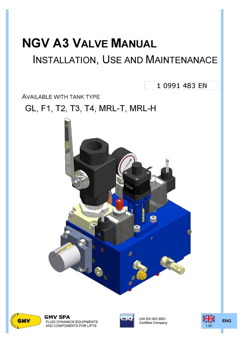
NGV EK VALVE
NGV-EK
V
ALVE
M
ANUAL
I
NSTALLATION
,
U
SE AND
M
AINTENANCE
1 0991 491 EN
A
VAILABLE WITH TANK TYPE
GL, F1, T2, T3, GL Dry, F1 Dry
1 0991 491
EN
-
23.08.2016
1.00 ENG
NGV-EK
V
ALVE
M
ANUAL
I
NSTALLATION
,U
SE AND
M
AINTENANCE
2 / 45
WARNING - IMPORTANT
GMV Spa declines all responsibility in case you do not follow the instructions in this document.
Particularly, may cause safety problems to the system and to the passengers, if you do not respect the
instructions of this manual, about :
- motor/pump power on and power off
- soft stop sequence
- sensors S1, S2 ed S3
WARNING
The automatic return to the landing in event of lack of voltage should be made moving the car to the
lowest floor. Returning to a landing floor that is not the lowest floor, may cause safety problems to the
system and to the passengers
Never move the sensors S1 S2 S3 !
The sensors are installed, adjusted and tested at the factory.
The change of their position should be performed only by authorized and
properly trained people.
Moving the sensors may cause safety problems, to the system and to the
passengers.
Displacing the sensors voids the warranty.
IMPORTAN PARAMETERS
5.11 Mode
The factory setting is : INSTALLATION
It's possible to change the parameter to NORMAL onlyafter you have completed:
•The installation of the main parties (car)
•The connection of all the signals of the shaft
5.4 p_stat min and
5.5 p_stat max
The parameters are adjusted at the factory on the following pressures:
Pmin (P min> = 12) = pressure calculated with empty car
(or Pmin of the motor / pump - 20)
Pmax = pressure with car fully loaded.
After the installation, to check reading the parameter (Menu 1.1), that the values match those entered and if
theyare different correct them with the ones detected.
These values refer to the run curve in NORMAL mode, and they are ignored in INSTALLATION
mode
All other parameters do not affect the installation, but are used to regulate in detail the system
working in NORMAL mode
ALARMS
ALARM ?
To prevent the appearance of some alarms is sufficient that :
•The pressure is at least 7-8 bar (Menu 1.1)
•The oil temperature is at least 5-8 ° C (Menu 1.2)
•he motor / pump will start only after the RUN signal, sent from the card
(Menu 1.5 output parameter N)
In case of alarms see the troubleshooting section of this manual and follow the
directions.
If you do not find a solution to the problem call for service.
SWITCH TO NORMAL MODE AT THE END OF THE INSTALLATION
1. Use the PT01 programmer to modify the parameter value 5.11 Mode = Normal
2. Verify that the following parameters (menu 5 Setting) are correct :
- 5.1 Lift Ratio : must match the value shown on the project layout
- 5.2 Jack Diam : must match the value shown on the project layout
- 5.4 Pstat min : with empty car must be equal to the value of the menu 1.1 Pressure
- 5.5 Pstat max : with car fully loaded must be equal to the value of the menu 1.1
Pressure
ENG
1.00
1 0991 491
EN
-
23.08.2016
3 / 45
NGV-EK
V
ALVE
M
ANUAL
I
NSTALLATION
,U
SE AND
M
AINTENANCE
INDEX
0 GENERAL SECTION 6
0.1
I
NTRODUCTION INFORMATIONS
6
0.1.1
D
EFINITIONS
6
0.1.2
T
ERMS AND SYMBOLS USED
6
0.1.3
R
ULES REFERENCE
6
0.2
D
OCUMENTS RELATED WITH INSTALLATION
6
0.3
S
AFETY PRECAUTION DURING INSTALLATION
6
0.4
T
OOLING
7
0.5
G
ENERAL ORDERS
7
1 FEATURES AND REQUIREMENTS 7
1.1
T
HE
NGV
EK
V
ALVE
7
1.2
L
A S
C
HEDA
NGV-EK01 8
1.3
I
L FLUIDO
8
1.4
H
OW THE
NGV
EK
WORKS
8
1.5
T
HE DOUBLE SAFETY
9
1.6
M
AIN FEATURES
10
2 INSTALLATION OPERATIONS 11
2.1
H
YDRAULIC CONNECTIONS
11
2.1.1
I
NPUT AND OUTPUT
-
POWER UNIT SIDE
1”1/4
VALVE
11
2.1.2
C
ONNECTION OF HYDRAULIC PIPES
11
2.1.2.1
C
ONNECTION WITH FLEXIBLE HOSE
11
2.1.2.2
C
ONNECTION WITH A RIGID PIPE
12
2.2
H
YDRAULIC CIRCUIT
12
2.3
E
LECTRICAL CONNECTIONS
13
2.3.1
C
ONTROL PANEL REQUIREMENTS
13
2.3.2
I
NTERVENTION TIME
13
2.4
O
PERATIONS PRELIMINARY TO CONNECTION
13
2.5
S
CHEMAS OF THE CONNECTIONS TO CONTROL PANELS
13
2.5.1
M
AIN
S
CHEMA
14
2.5.2
C
ONNECTION SCHEMAS FOR
S
IGNALS AND POWER
15
2.5.3
C
ONNECTION SCHEMAS FOR SOFT
-
STOP
16
2.6
C
ONNECTIONS TO THE TERMINAL AND TO THE MOTOR
17
2.6.1
S
UBMERGED MOTOR
17
2.6.2
D
RY MOTOR
17
3 NGV-EK CONTROL BOARD (CARD) 18
3.1
F
EATURES
18
3.1.1
H
OW TO INTERFACE
19
3.1.1.1
M
AIN CONFIGURATIONS
19
3.1.1.2
S
OFT
S
TOP MODE
19
3.1.2
S
IGNALLERS
19
3.2
C
ONNECTIONS
20
3.2.1
C
ONTROL PANEL INTERFACE
20
3.2.2
V
ALVE INTERFACE
21
3.2.3
V
ALVE INPUTS INTERFACE
22
3.2.4
J
UMPERS
22
3.2.5
E
XTENSIONS INTERFACE
22
3.2.6
U
SER INTERFACE
23
3.2.7
M
OTOR PUMP INTERFACE
(MP-ISO) 23
3.3
S
IGNALS AND COMMANDS SEQUENCE
23
3.3.1
U
PWARD AND DOWNWARD DIAGRAM
23
3.4
D
ECELERATION DISTANCES
25
3.5
µ
SD,
P
ARAMETERS AND
S
OFTWARE
25
3.5.1
µ
SD
M
EMORY
25
3.5.2
P
ARAMETERS
27
3.5.2.1
S
TORAGE
27
3.5.2.2
L
OADING
27
3.5.3
S
OFTWARE UPDATE
27
4 ADJUSTMENTS AND TEST 27
4.1
A
DJUSTMENT OF THE OVERPRESSURE VALVE
(OPP/MPS) 28
4.2
R
AM PRESSURE ON THE
VSMA
ADJUSTMENT
29
4.3
P
IPE RUPTURE VALVE
(VC)
TEST
29
4.4
T
EST OF DEVICES THAT PREVENT UNCONTROLLED MOVEMENT
29
1 0991 491
EN
-
23.08.2016
1.00 ENG
NGV-EK
V
ALVE
M
ANUAL
I
NSTALLATION
,U
SE AND
M
AINTENANCE
4 / 45
4.4.1
P
REREQISITES
29
4.4.2
T
EST IN UP DIRECTION
30
4.4.3
T
EST IN DOWN DIRECTION
30
4.5
TEST
OF THE MONITORING SYSTEM
31
5 PROGRAMMING 31
5.1
S
YSTEM PARAMETERS
31
5.2
C
OMPLETE MENÙ
32
5.3
M
ENÙ
33
-
1
-
D
IAGNOSTICS
33
-
2
-
A
LLARMS
34
-
3
-
R
ESET ALLARMS AND FAULT
34
-
4
-
A
DJUSTMENTS
34
-
5
-
S
ETTINGS
35
-
6
-
U
PWARD PARAMETERS
35
-
7
-
D
OWNWARD PARAMETERS
36
-
8
-
O
UTPUT FUNCTIONS
36
-
9
-
T
EST
37
-
10
-
A
DVANCED PROGRAMMING
37
-
11
-
P
ARAMETERS ON
M
ICRO
S
ECUR
D
IGITAL
37
-
12
-
S
OFTWARE UPDATE
38
5.4
C
HART OF OUTPUT PROGRAMMABLE FUNCTIONS
38
5.5
C
HART OF FAILURES
38
5.5.1
F
AULT
A
NALYSIS
39
5.6
A
CCESSORIES
40
6 MAINTENANCE AND FAULT ANALYSIS 40
6.1
P
ROGRAMMED MAINTENANCE
40
6.2
P
ERIODICAL MAINTENANCE
A
ND CHECKS TABLE
40
6.3
M
AINTENANCE SCHEDULES
41
6.4
A
DJUSTING THE SENSORS
42
6.4.1
S
ENSOR
S1 43
6.4.2
S
ENSOR
S2 43
6.4.3
S
ENSOR
S3 43
7 CERTIFICATES 44
7.1
T
YPE EXAMINATION
44
7.2
C
ONFORMITY
44
ENG
All rights reserved.
Any kind of exploitation in any form and by any means is forbidden without a written permission of GMV Spa.
GMV Spa, within technical or manufacturing progress, reserves the right to modify parts or this manual without notice.
Drawings, descriptions and data included in this manual are indicatives.
For all the data not included in this manual refer to the documents of any single part.
To guarantee the products security, do not use spare parts not genuine or not approved by GMV Spa.
GMV Spa will not assume any responsibility if the instructions included in this manual are not observed.
Informazioni e supporto:
GMV SPA
FLUID DYNAMICS EQUIPMENTS AND
COMPONENTS FOR LIFTS
UNI EN ISO 9001
Certified Company
GMV SPA
Via Don Gnocchi, 10 - 20016 PERO – Milano (Italy)
TEL. +39 02 33930.1 - FAX +39 02 3390379
http://www.gmv.it - e-mail: [email protected]
Go to www.gmv.it to check availability
of updates about this file or other informations about GMV products.
ENG
1.00
1 0991 491
EN
-
23.08.2016
5 / 45
NGV-EK
V
ALVE
M
ANUAL
I
NSTALLATION
,U
SE AND
M
AINTENANCE
Main acronyms and abbreviations
1 Regulator of the pressure safety valve (pressure limiter)
5
Shut-off valve / Screw for rupture valve test
6
Shut-off valve for pressure gauge exclusion
7
Regulator of the ram pressure (only 2:1 acting jacks)
10
Regulator of the pressure safety valve (hand pump)
BOX
Interface box (NGV-EK / Control panel)
C1
Chamber of the VRP
C2
Inlet chamber
C3
VB outlet chamber
C4
Chamber of the VRP pilot spool
CARD
NGV A3 control card
D
Downward signal
DAL
Levelling auxiliary device (Micro-Levelling)
DN
Downward
FLT
Filter
ISP
Inspection gauge fitting
J
Jack
K
Non-return valve
M, Ma
Motor
M1
Spool of the VRP
MAN
Pressure gauge
ML
Manual lowering button
MP
Motor / pump
MPS
Maximum pressure spool
NGV-EK
NGV EK Valve (Complete)
OFF
Not powered
ON
Powered
OPP
MPS pilot valve
P
VRP pilot spool
PAM
Hand pump
PT Pressure transducer
QM Control panel
RDY Ready - Ready signal (card output to control panel)
RO Oil heating resistance
R/S
1,2
Shut-off valve
1
/ Silencer
2
RT Motor thermistors
RUN Run - Start signal (card output to control panel)
S1 (VRP) Sensor to control the VRP closing
S2 (VBC) Sensor to control the VB closing
S3 (VBO) Sensor to control the VB opening
SM Stepping motor
TO Oil thermostat
TT Temperature transducer
UP Upward / Up - command of starting upward (card to control panel)
V0 Speed : high
V1 Speed : medium
V2 Speed : inspection
V3 Speed : micro-levelling
VAL
NGV EK Valve
(Valve only)
VB Main flow adjustment valve
VBP
By-pass valve
VC Rupture valve
VMD Downward solenoid valve
VR Non-return valve (flow)
VR1 Non-return valve (inlet)
VR2 Non-return valve (outlet)
VRP Non-return valve - controlled
VS Upward signal
VS1, VS10 Pressure safety valve
1 0991 491
EN
-
23.08.2016
1.00 ENG
NGV-EK
V
ALVE
M
ANUAL
I
NSTALLATION
,U
SE AND
M
AINTENANCE
6 / 45
VSMA Lowering valve manual / electrical
0GENERAL SECTION
0.1 INTRODUCTION INFORMATIONS
0.1.1 DEFINITIONS
In this manual are used the definitions in EN81-2: Safety rules for the construction and installation of lifts,
EN1050: Safety of machinery - Principles for risk assessment, ISO3864: Safety colours and safety signs, and
the following apply:
0.1.2 TERMS AND S MBOLS USED
NOTE
Indicates information which contents must be seriously taken in consideration.
WARNING
Indicates that the described operation is likely to cause, damages to the system or physical damages
if performed without complying with the safety standards.
0.1.3 RULES REFERENCE
For all definitions not included in this manual please refer to rules and local laws in force, following,
particularly:
EN 81-2: Safety rules for the construction and installation of lifts,
EN 1050: Safety of machinery - Principles for risk assessment,
ISO 3864: Safety colours and safety signs.
0.2 DOCUMENTS RELATED WITH INSTALLATION
The documents to use for the installation are those required by the EN81-2:1998 and by the rules in force,
particularly the following:
- T
HIS INSTALLATION MANUAL
- W
IRING AND HYDRAULIC DIAGRAMS
(EN81-2:1998
16.2
A
)
6
AND
7).
All the documentation for a correct and safe installation, must be stored by the installation responsible.
Please remember that this documentation is considered part of the plant and must be complete, well stored
and unabridged in every part.
In order to maintain the readability, the documentation shouldn’t be damaged and shouldn’t have missing
parts. Moreover, do not tear or deteriorate sheets during consulting.
0.3 SAFET PRECAUTION DURING INSTALLATION
WARNING
Before start all kind of installation operation.
ALWAYS verify that al the safety devices, mechanical or electrical, are active and working properly.
ENG
1.00
1 0991 491
EN
-
23.08.2016
7 / 45
NGV-EK
V
ALVE
M
ANUAL
I
NSTALLATION
,U
SE AND
M
AINTENANCE
0.4 TOOLING
Use standard building-yard tooling for the installation.
0.5 GENERAL ORDERS
The valves should be maintained in good working order in accordance with the European Standards.
To this effect, regular maintenance of the installation shall be carried out, to ensure, in particular, the safety
of the installation.
The safety of an installation should take into account the ability to be maintained without causing injury or
damage to health.
Regular maintenance of the installation should be carried out to ensure the reliability of the installation.
The access and the associated environment should be maintained in good working order.
The competence of the maintenance person within the maintenance organization should be continuously
updated.
NOTE
We inform the owner of the installation that the qualification of the maintenance organization needs to
be in conformity with the rules applicable in the country in which the installation operates; if no rules
exist, the qualification can be ensured by a certified EN ISO 9001 quality system supplemented if
necessary to take into account the specific features of the installation.
1FEATURES AND REQUIREMENTS
1.1 THE NGV EK VALVE
The NGV EK valve with:
- the new Fluitronic digital technology.
- the “Stepping System” device
- the possibility to use ecological fluid or traditional mineral oil
- the working pressure between 12 and 45 bar
Guarantees :
- Increased reliability of the control system
- Best performance
- Reduction of costs
- Reduction of the installed power (up to 20%)
- Reduction of consumptions up to 40% (*)
- Reduction of the travel time
- Reduced use of heat exchangers
- Constant downward speed regardless of the load
- Compliance with various regulatory and environmental requirements
(Ex. compliance with the Directive 2006/118/EC on the environment)
- More safety thanks to double lock, already integrated in the product
conforms to the rule EN 81-2:2010
Offer:
- Ideal solution for renovation and MRL systems
- The most advanced system of control for lift
- Technology in line with the latest trends in the control field
- Speed up to 1 m/s
- Downward speed greater than the upward up to +20%
- Ride comfort comparable to a VVVF electric and no consumption in
standby mode
- Maintenance speed adjustable
(*) Maximum value reached under optimal conditions and in combination
with other products GMV
- The driving option
I
NTERNAL
F
EED
B
ACK
(C
AR
L
OAD
/
T
EMPERATURE
)
The choice to immediate savings, interfaced with all, existing and
new systems
Not require encoder, reduce consumption up to 20% *
The valve, stored the operating characteristics, reading changing of
pressure and temperature, make the appropriate corrections to
obtain car speed profiles with low deviations from the ideal profile.
* Compared to a traditional valve
1 0991 491
EN
-
23.08.2016
1.00 ENG
NGV-EK
V
ALVE
M
ANUAL
I
NSTALLATION
,U
SE AND
M
AINTENANCE
8 / 45
1.2 LA SCHEDA NGV-EK01
The NGV-EK01 card
- Is designed for applications where you can not install a power unit with
a standard NGV A3 valve and in particular for those installations
where the interface with the control panel is typical of a power unit
with the 3010 valve or similar.
- Is particularly suitable in event of restructuring, modernization and / or
where the control panel, born to operate with a power unit with 3010
valve or similar, it is not suitable to be used with a standard NGV-A3
valve.
The NGV-EK01 card, also
- Can be extended with an additional device in order to manage the
uncontrolled movement of the car (amendment A3).
The NGV-EK01 card coupled to a power unit with NGV-EK valve, is
advantageous because :
- Can be installed on any system in which the control panel, both
existing and new, does not meet the requirements to control of a
power unit with standard NGV-A3 valve.
- interfaces itself with the control panel only using terminals and do not
requires changes to the electrical/working schema
- the absorbing power is less than two solenoid and does not require
changes to the control panel.
- the use of a bypass valve that allows the starting of the motor-pump
with the VB spool closed, makes easier the interfacing with the control
panel.
- Indicates the alarm status via a single relay contact (exchange
contact).
1.3 IL FLUIDO
GMV use and recommend an hydraulic fluid ISO VG 46 that :
- Thanks to classification as category HEES, as rule ISO-UNI 6743-4
and its biodegradability index > 90%, according to standard CEC L33-
A-93, is acceptable from an environmental point of view.
- Thanks to the synthetic base (ISO VG 46 ) and its viscosity index
(>140), higher than the traditional mineral oil, allowing greater stability,
ensuring better performance against wear and aging on systems as
lifts for persons and goods, in accordance with the environmental
directive 2006/118/EC.
- Thanks to a flash point above 220°C compared to the 140°C of the
traditional mineral oil it is safer and reduces the risk of fire.
1.4 HOW THE NGV EK WORKS
The NGV valve is made with a non-return valve VR, a control spool VB controlled by a stepping motor and by
a system with pilot operated non-return valve VRP - P(moved in opening by the electro-valve VMD).In case of
uncontrolled movement the P spool operates to avoid the lift downward
Valve VR It is a valve that prevent , during the downward, the oil inlet to the pump.
It forces the oil coming from the VRP C2 to pass through the spool VB and then in the C3 and in
the tank T1.
Valve
VRP-P It is the pilot operated non-return valve, requested by rules.
During upward the valve works only as ON/OFF, the spool VRP opens or closes depending on
the oil that comes. Its position is determined by the ratio between the pressure that develops in
the chamber C2 and the one that occurs in chamber C1
During downward, instead, it opens the oil way to the valve block (chamber C2). Its opening is
made by the pushing of the piston P that is opened by the pilot operated VMD valve
Spool VB It’s the main part of the control block.
It adjusts the oil quantity that should be discharged and determines all the movements of the car
Its movement is controlled by a stepping motor coupled to the spool VB, through a screw-nut
coupling (necessary to transform the rotatory motion into translatory).
The spool adjusts both the upward phase (with a direct control of the oil that should be
discharged and, indirectly the oil for the cylinder) than that of downward (directly)
Valve
VBP This solenoid valve controls the fluid flow from the motor-pump towards the valve, and
consequently towards the piston. The VBP, when de-energized deflects the flow in exhaust,
ENG
1.00
1 0991 491
EN
-
23.08.2016
9 / 45
NGV-EK
V
ALVE
M
ANUAL
I
NSTALLATION
,U
SE AND
M
AINTENANCE
(by-pass) when excited directs the flow towards the valve, allowing then to be able to supply the motor
pump with the VB spool closed. The valve is energized after the VB opening and it is de-
energized at the end of Soft Stop or when occurs an advance interruption of the manoeuvre.
All the other valves have features of safety, pilotage, etc. For example :
MPS+OPP Maximum pressure valve with pilot
5 Overspeed screw
VSMA Emergency lowering valve
1.5 THE DOUBLE SAFET
For the double safety the system has two spools in series, the VRP and the VB.
Both work together to stop the car in different ways between upward and downward
UPWARD
The spool VB controls acceleration and deceleration.
During the approach to the landing, the spool VB, will be almost fully open to discharge a quantity of oil
equal to: Qt = Qp - Qc
where
Qt = Oil sent to the drain through the VB, Qp= Pump flow
Qc= Flow to the cylinder, corresponding to the car speed
The car stop at the landing is made by opening completely the VB and bringing the value of Qt = Qp. As a
result Qc becomes zero.
The car stops when the pressure of the chamber C2 become equal to the pressure of the chamber C1
(Static pre
ssure of the system). In this case, the VRP spool closes, because is pushed by the pressure and
by the spring, and the car stops at the landing.
DOWNWARD
The downward phase is simpler and, after the opening of the VRP spool, the car speed is controlled by the
VB spool. To a more opening of the spool corresponds an higher speed of the car
The phase of arrival at the landing is determined by the following events:
The VRP spool is opened by the push of the spools P, controlled by the VMD pilot valve
The VB spool closes to stop the car
The VMD valve, raised the landing, is de-energized and consequently the VRP spool closes.
During standard operation of the system, both upward and downward, the proper working of the two
spools (VRP and VB) acting in series, is controlled by three switches :
One, (S1) installed on the VRP, to control the full close position.
Two (S2, S3) installed on the VB, to control the full close and the full open positions
During all phases the system control that the spools reach the correct open and close position.
If this do not happen, the system send an alarm to the control panel, which must turn the system into the
out of service status.
1 0991 491
EN
-
23.08.2016
1.00 ENG
NGV-EK
V
ALVE
M
ANUAL
I
NSTALLATION
,U
SE AND
M
AINTENANCE
10 / 45
WARNING
Needful prerequisite of the control panel, when the system is outside of the doors unlocking zone, is
that it does not send commands to the card and/or the motor / pump.
1.6 MAIN FEATURES
Valve Type
I.a NGV-EK
Minimum operating pressure
I.b 12 bar
Maximum operating pressure
I.c 45 bar
Test speed
I.d 1 m/s
Temperature operating range
5°C - 70°C
Rated pump flow range
55 - 300 l/min
ENG
1.00
1 0991 491
EN
-
23.08.2016
11 / 45
NGV-EK
V
ALVE
M
ANUAL
I
NSTALLATION
,U
SE AND
M
AINTENANCE
2INSTALLATION OPERATIONS
WARNING
During the installation never exclude the safety devices and never connect the motor/pump directly to
the power supply
2.1 H DRAULIC CONNECTIONS
2.1.1 INPUT AND OUTPUT - POWER UNIT SIDE 1”1/4 VALVE
1"
14
OUT
M8
OUT
1"
14
IN
M8
OUT
M8
OUT
M8
OUT
12x8
PAM
2.1.2 CONNECTION OF H DRAULIC PIPES

55 ÷ 100
1”1/4 1” 1” x M36 1” - 1” x M36 1”
100 ÷ 150 1” x M45 1”1/4 35 1” x M45 1”1/4
180 ÷ 216 1”1/4 1”1/4 x M45 1”1/4 x M45
250 ÷ 300 - 1”1/2 1”1/2 x M52 1”1/2 42 1”1/2 x M52 1”1/2
2.1.2.1 CONNECTION WITH FLEXIBLE HOSE
•Remove the gear and the cutting ring from the terminal
connection of the silencer.
•Ensure that the terminal connection is well fixed on the
silencer.
•Clean and oil the threading and their seats.
•Fix the flexible hose making sure it is thoroughly tightened.
WARNING
Ensure that there is no dirty inside the pipe. These
impurities could damage the sealing of the piston and of
the valve block and inhibit the correct operation of the
system.
1 0991 491
EN
-
23.08.2016
1.00 ENG
NGV-EK
V
ALVE
M
ANUAL
I
NSTALLATION
,U
SE AND
M
AINTENANCE
12 / 45
2.1.2.2 CONNECTION WITH A RIGID PIPE
•Cut at 90° the head of the pipe with a saw (do not use a pipe-cutter)
•Do not let metal residuals fall into the pipe and eliminate the burrs internally and externally.
•Remove the gear and the cutting ring of the terminal connection and insert it on the pipe.
•Ensure that the cutting ring is inserted as indicated in image
•Ensure that the terminal connection is well fixed on the silencer.
•Clean and lubricate the threading and the connection seat with
a slight oil veil.
•Insert the pipe into the cone at 24° up to lay it on the stop limit
of the cone itself.
•Screw thoroughly the gear by hand until it is felt that the cutting
gear lays perfectly to the nut.
•Then screw the nut using a wrench until the cutting edge of the
ring is in contact with the tube and prevents it from rotating.
•Keep the pipe against its stop to avoid the rotation, screw the
fixing nut by 3/4 rev. In doing so the ring engraves with the
necessary depth the external part of the tube and rises a
border in front of its cutting edge.
•Loose the nut and check that the pipe has all around a well
risen border. The border must cover 70% of the front part of
the cutting ring.
•Fix the pipe, close the nut with a wrench until a certain
resistance is felt; from this moment on screw for a further 1/4
turn, contrasting wrench against wrench.
WARNING
Ensure there is no dirty inside the tube. The impurities could damage the sealing of the piston and of
the valve block and inhibit the correct operation of the plant.
2.2 H DRAULIC CIRCUIT
ENG
1.00
1 0991 491
EN
-
23.08.2016
13 / 45
NGV-EK
V
ALVE
M
ANUAL
I
NSTALLATION
,U
SE AND
M
AINTENANCE
2.3 ELECTRICAL CONNECTIONS
2.3.1 CONTROL PANEL REQUIREMENTS
The control panel must send to the power unit at least the following signals:
ID
COMAND
ID
CARD
S
EGNAL
/
COMMAND
F
EATURES
VS
/
MP-ISO
VMP
/
AUX Upward 24…60Vdc/ac 80…180Vdc (230 Vac)
V0 VML High Speed 24…60Vdc/ac 80…180Vdc (230 Vac)
D VD
(VMD) Downward 24…60Vdc/ac 80…180Vdc (230 Vac)
The control panel must to receive and to understand correctly at least the following signals:
ID
COMAND
ID
CARD
S
EGNAL
/
COMMAND
F
EATURES
- 10-11-12 Alarm 1A@250Vac
WARNING
The control panel, when receive a FAULT signal from the NGV-EK card (Connector X1 output
10,11,12), should not send commando to the valve and/or the motor/pump
In FAULT condition the motor/pump group should NOT be active
WARNING
To detect the unintended movement of the car the system use the circuit required by paragraph 7.7.1
and 14.2.1.2 of the rule EN 81-2:2010. This circuit, if it detects a movement of the car, with doors not
closed, outside the unlocking zone, prevents the control panel to send any command to the valve.
The system restore should be performed only by an authorized and properly trained person.
•Distance of setting: ± 200 mm
•Maximum time for the intervention of the circuit 270 ms
For other data or signals sequence see next paragraphs of this manual
2.3.2 INTERVENTION TIME
0
Origin
2
3
6
0
8
7
4
5
1
1
Car speed in the instant of
intervention of the bracking device
≤1,3 m/s
2
Speed
3
Response time of the device that
detects the unintended movement
of the car ≤270 ms
4
Response time of the braking
devices ≤200 ms
5
Time
6
Time from start of the unintended
movement to the instant in which
the car sensor leaves the doors
area (dimension = ± 200 mm)
7
Stoping time of the car ≤500 ms
8
Point in which the car stops
0-8
between 0 and 8 the maximum
distance travelled is ≤100 cm
2.4 OPERATIONS PRELIMINAR TO CONNECTION
0 - OFF
0 - OFF
+
2.5 SCHEMAS OF THE CONNECTIONS TO CONTROL PANELS
In the following pages the schemas of the connections between valve / NGVA3 card and control panels.
1 0991 491
EN
-
23.08.2016
1.00 ENG
NGV-EK
V
ALVE
M
ANUAL
I
NSTALLATION
,U
SE AND
M
AINTENANCE
14 / 45
2.5.1 MAIN SCHEMA
W25
~
~~
--
L
A+
A+A+ N
A-
A-A-
++ +
~
~
18÷30V~
24÷40 V
=
18÷30V~
2200÷4700 F
50V
µ
V
ENG
1.00
1 0991 491
EN
-
23.08.2016
15 / 45
NGV-EK
V
ALVE
M
ANUAL
I
NSTALLATION
,U
SE AND
M
AINTENANCE
2.5.2 CONNECTION SCHEMAS FOR SIGNALS AND POWER
Scheme Mode 0, 1 Scheme Mode 2
H
L
H
LL
H
L
H
VMP CV1 VML CV2 CV2 AUX CV3 CV3
CVCVVD VP EM+EM-
+IN0 0PE X13
X16
J7
J8
J9
X5
X7
J6
X6
4
1
CARD
1
2
VMP 1
2
VML
1
2
VMD1
1
2
VMD
V+
V-
M 0,1
H
L
H
LL
H
L
H
VMP CV1 VML CV2 CV2 AUX CV3 CV3
CVCVVD VP EM+EM-
+IN 0 0PE
X13
X16
J7
J8
J9
X5
X7
J6
X6
4
1
CARD
1
2
VML
1
2
VMD1
1
2
VMD
V+
V-
M 2
U
V
M
MP-ISO
Scheme Mode 3,4 Scheme W25
H
L
H
LL
H
L
H
VMP CV1 VML CV2 CV2 AUX CV3 CV3
CVCVVD VP EM+EM-
+IN 0 0PE X13
X16
J7
J8
J9
X5
X7
J6
X6
4
1
CARD
1
2
VMP
1
2
VML
1
2
VMD1
1
2
VMD
V+
V-
M 3,4
U
V
M
MP-ISO
-+
25W 24 V
DC
= + 5% -20%
PE
H
L
H
LL
H
L
H
VMP CV1 VML CV2 CV2 AUX CV3 CV3
CVCVVD VP EM+EM-
+IN 0 0PE X13
X16
J7
J8
J9
X5
X7
J6
X6
4
1
CARD
W25
1 0991 491
EN
-
23.08.2016
1.00 ENG
NGV-EK
V
ALVE
M
ANUAL
I
NSTALLATION
,U
SE AND
M
AINTENANCE
16 / 45
2.5.3 CONNECTION SCHEMAS FOR SOFT-STOP
Soft Stop Scheme mode 1
CARD
SS1
OS1
OS2
OS3
LS
LD
0V
+24
LC
X3
24...48V / 0V
0V / 16...48V
NO
QM
CFS
CFS =
Upward stop
switch
Soft Stop Scheme mode 2
SS2
X3
16...48V / 0V
0V / 24...48V
NC
QM
CFS
CARD
OS1
OS2
OS3
LS
LD
0V
+24
LC
CFS =
Upward stop
switch
Soft Stop Scheme mode 3
CARD
SS3
CF
QM
10
11
12
21
22
31
32
41
42
SC-
SC1
SC2
SC3
SC-
X1
X2
X4
NC
NC
NO
LS
CL
0V
―
Existing
circuit
―
Changes
to make
ENG
1.00
1 0991 491
EN
-
23.08.2016
17 / 45
NGV-EK
V
ALVE
M
ANUAL
I
NSTALLATION
,U
SE AND
M
AINTENANCE
2.6 CONNECTIONS TO THE TERMINAL AND TO THE MOTOR
2.6.1 SUBMERGED MOTOR
∆
U1
W2
V1
U2
W1
V2
U1
W2
V1
U2
W1
V2
RO2
RO1
TO1
TO2
RT1
RT2
RO2
RO1
TO1
TO2
RT1
RT2
M
3~
TORO RT
150 mm
230-400V 400-690V
230V ∆
Y-
∆
-
400V
Y
∆
Y-
∆
RO - Oil heating resistance
TO - Oil thermostat
RT - Motor thermistors
Y-∆
U1
W2
V1
U2
W1
V2
U1
W2
V1
U2
W1
V2
RO2
RO1
TO1
TO2
RT1
RT2
RO2
RO1
TO1
TO2
RT1
RT2
M
3~
TORO RT
150 mm
Y
U1
W2
V1
U2
W1
V2
U1
W2
V1
U2
W1
V2
RO2
RO1
TO1
TO2
RT1
RT2
RO2
RO1
TO1
TO2
RT1
RT2
M
3~
TORO RT
150 mm
2.6.2 DR MOTOR
∆
U1 W2
V1 U2
W1 V2
RO2
RO1
TO1
TO2
RO2
RO1
TO1
TO2
M
3~
TORO
RT
150 mm
230-400V 400-690V
Impossibile
visualizzare
l'immagine
collegata. È
possibile che il file
sia stato spostato,
rinominato o
eliminato. Verificare
che il collegamento
rimandi al file e al
percorso corretti.
230V ∆
Y-
∆
-
400V
Y
∆
Y-
∆
RO - Oil heating resistance
TO - Oil thermostat
RT - Motor thermistors
Y-∆
U1 W2
V1 U2
W1 V2
RO2
RO1
TO1
TO2
RO2
RO1
TO1
TO2
M
3~
TORO
RT
150 mm
Y
U1 W2
V1 U2
W1 V2
RO2
RO1
TO1
TO2
RO2
RO1
TO1
TO2
M
3~
TORO
RT
150 mm
1 0991 491
EN
-
23.08.2016
1.00
ENG
NGV-EK
V
ALVE
M
ANUAL
I
NSTALLATION
,U
SE AND
M
AINTENANCE
18 / 45
3NGV-EK CONTROL BOARD (CARD)
H
L
H
LL
H
L
H
2012_026 Lc
NGV-EK01
10 11 12 21 22 31 32 41 42
OS1OS2OS3LS LD 0V+24LC
SC- SC1 SC2 SC3 SC- VMP CV1 VML CV2 CV2 AUX CV3 CV3
CVCVVD VP EM+EM-
VBP
CVVMD CV EM+EM-P1+T-T+ P1-P2+P2-+ -S1-S2+-S3+
+IN 0 0PE
4
1
X14 X12 X11 X10 X9 X8 X7
X1 X2 X3 X4 X5
X13
X6
X15
J3 J1 J2
J7 J8 J9
J6
J4
X16
LV1
LR1
CR2030
3.1 FEATURES
The hardware features of the card NGV-EK are:
# DESCRIPTION VALUE
C
ONTROL PANEL INTERFACE
01 Power supply of the card 24V= -5%, +20%
02 Power supply of the card with power supplier (ALM03) 20…180(230) Vdc/(Vac)
Max 30W
03 Maximum consumption 25W
04 Voltage input VMP,VML,AUX, MD, two range selectable by jumper 20...60Vac/dc
80…180 (230) Vdc/(Vac)
05 Voltage input VMD 20…180 (230) Vdc/(Vac)
06 Voltage input VBP (by-pass) 20…180 (230) Vdc/(Vac)
07 Relay output with voltage free contact
according to EN81-2 for distances and isolation up to 250V 24Vdc / 2A (min 20Vdc/10mA)
250 Vac /2A
08 Inputs for well sensors (quantity 2) 24…48Vdc , 10mA max
1 changeover contact
09 Additional inputs AUX (quantity 3) 48…180 (230) Vdc/(Vac)
V
ALVE
I
NTERFACE
10 Input for pressure sensors (quantity 2 for transducers with 2 wires) 12Vdc 4…20mA max
11 Input for fluid temperature sensor (PTC) 1000
Ω
/ 25°C
12 Power voltage sensors VRP and VB
(2 sensors ON/OFF 12V or linear 0...5V, 1 sensor ON/OFF 12V) 12Vdc
13 Step Motor Command with the possibility of monitoring the rated
current and the connection breaking 12...52Vdc, 1,5Arms
U
SER
I
NTERFACE
14 Rj45 port for PT01 / remote Pc Seriale RS232
15 Data and working parameters storage / saving to
µ
SD (up to 8Gb)
16 Updating software from
µ
SD (up to 8Gb)
E
XPANSIONIS
17 I/O extender connector Flat 26 poles
18 Battery for clock / calendar CR2030
ENG
1.00
1 0991 491
EN
-
23.08.2016
19 / 45
NGV-EK
V
ALVE
M
ANUAL
I
NSTALLATION
,U
SE AND
M
AINTENANCE
3.1.1 HOW TO INTERFACE
Different interfacing modes are provided with the various existing configurations of the control panel, settable
by the PT01 programmer through the menu.In case of failure to supply directly the NGV-EK card with the
required voltage, you must use a suitable power supply, type-ALM 03, capable to provide the correct voltage
deriving it from the valve supply voltage available in the control panel. (01-02-03)
The solenoid valve VBP (by-pass) uses the same power supply of the VMD (already available in the control
panel). Consequently, to connect it to the card, just provide only one terminal,since it is busy only for the
upward while VMD is not powered.Therefore,you do no change the circuit layout (05-06)
There are 4 inputs for commands,mutually isolated from each other, signed VMP-VML-AUX-VD, with a
driving voltage independently configurable for each input in one of the two available ranges (04)
In case the control panel is not set for the Soft Stop and the Unintended Car Movement monitoring,just use
the lift shaft signals. On the same connector there is voltage-free changeover contact, to realize the filter-
signal stop for Soft Stop. These signals are combined with those of the existing sensors
WARNING
If the command for the upward solenoid valve (VMP) is not available it is necessary to use the device
MP-ISO in order to detect the motor-pump power.
3.1.1.1 MAIN CONFIGURATIONS
6.9
M
ODE
6.10
S
OFT
S
TOP
P
OWER UNIT TO REPLACE
E
XISTING
C
OMMANDS
C
ONNECTED TO
:
0 0 3010 + VMP + Soft-stop VMD / VML / VMP VD / VML / VMP
1 1,2,3 3010 + VMP VMD / VML / VMP VD / VML / VMP
2 1,2,3 3010 VMD / VML VD+MP-ISO / VML
3 0 3010 + 2CH + Soft-stop VMD / VML / VMP VD+MP-ISO / VML / AUX
4 1,2,3 3010 + 2CH VMD / VML / VMP VD+MP-ISO / VML / AUX
3.1.1.2 SOFT STOP MODE
Using the parameter 6.10 you can set some different Soft Stop working way.
Mode 0 Soft Stop managed from the control panel.
The Soft Stop starts when the VMP signal fails
Mode 1 Soft Stop managed by NGV-EK01, LS normally open.
Soft stop starts when, during the re-leveling, the LS signal becomes active and the
time set with parameter 6.11 is elapsed.
Mode 2 Soft Stop managed by NGV-EK01, LS normally open.
Soft stop starts when, during the re-leveling, the LS signal becomes not active and the
time set with parameter 6.11 is elapsed.
Mode 3 Soft Stop managed by NGV-EK01, SC1 normally open.
Soft stop begins when, during the re-leveling, the SC1 signal becomes active.
Please refer to the application diagrams for details of interfacing (§ 3.3.1)
3.1.2 SIGNALLERS
GREEN LED Power supply
status
O
FF
Not powered
+ -S1-S2+-S3+
X11X12X13
LV1
LR1
J5 BAT1
J2J1
J3 X14
J4
F
LASHING
Power out of range
O
N
Correctly powered
RED LED
Alarm status
O
FF
No alarm
+ -S1-S2+-S3+
X11X12X13
LV1
LR1
J5 BAT1
J2J1
J3 X14
J4
F
LASHING
Alarm that stops the system work
O
N
Alarm that do not stops the system work
PT01
Card status D
ISPLAY
Show errors and settings
1 0991 491
EN
-
23.08.2016
1.00 ENG
NGV-EK
V
ALVE
M
ANUAL
I
NSTALLATION
,U
SE AND
M
AINTENANCE
20 / 45
3.2 CONNECTIONS
3.2.1 CONTROL PANEL INTERFACE
The interfacing with the control panel is made via removable terminal connectors defined as follows:
Connettor X1, step 5,0 mm
Pos. Mark Features Description
2012_026 Lc
NGV-EK01
10 11 12 21 22 31 32 41 42
OS1OS2OS3L S LD 0V+24L C
X1
X2
J5
X15
X3


1 10 Contact NO 1A@250Vac Alarm Output
- insulation 3 mm
2 11 Contact COM
3 12 Contact NC 1A@250Vac
4 21 Contact NO 1A@250Vac Output 21-22 (Out 1)
- insulation 3 mm
5 22 Contact COM
Connettor X2, step 5,0 mm
Pos. Mark Features Description
2012_026 Lc
NGV-EK01
10 11 12 21 22 31 32 41 42 O S1OS2OS3LS LD 0V+24L C
X1
X2
J5
X15
X3


1 31 Contact COM Output 31-32 (Out 2)
- insulation 3 mm
2 32 Contact NC 1A@250Vac
3 41 Contact COM Output 41-42 (Out 3)
- insulation 3 mm
4 42 Contact NC 1A@250Vac
Connettor X3, step 3,5 mm
Pos. Mark Features Description
2012_026 Lc
NGV-EK01
10 11 12 21 22 31 32 41 42 O S1OS2OS3LS LD 0V+24L C
X1
X2
J5
X15
X3


1 OS1 Contact NO 1A@48Vdc Output AUX
- insulation 1,5 mm
- Stop signal filter for SoftStop
2 OS2 Contact COM
3 OS3 Contact NC 1A@48Vdc
4 LS 24...48V= Input mono/bistable LS

5 LD Input mono/bistable LD
6 LC Common Common LS-LD Positive + or
negative -
7 +24 +24Vdc@50mA Output Aux +24Vdc

8 0V Common Common for +24Vdc
Connettor X4, step 5,0 mm
Pos. Mark Features Description
L
H
LL
H
L
H
LD 0V+24LC SC- SC1 SC2 SC3 SC- VMP CV1 VML CV2 CV2 AUX CV3 CV3
+IN0 0PE
X16
J7
J8
J9
X5
X4
J6
X6
41


1 SC- Common Common inputs SC1 / 2 / 3
2 SC1 48…180Vdc (230Vac) Inputs SC1 SC2 SC3
- insulation 3 mm
3 SC2
4 SC3
5 SC- Common Common inputs SC1 / 2 / 3
Connettor X5, step 5,0 mm (see Jumpers for voltage)
Pos. Mark Features Description
L
H
LL
H
L
H
LD 0V+24LC SC- SC1 SC2 SC3 SC- VMP CV1 VML CV2 CV2 AUX CV3 CV3
+IN0 0PE
X16
J7
J8
J9
X5
X4
J6
X6
4
1


1 VMP 24…60Vdc/ac,
80…180Vdc (230Vac)
Input command up direction
2 CV1 Common Common VMP
3 VML 24…60Vdc/ac,
80…180Vdc (230Vac)
Input commad high speed
4 CV2 Common Common VML, bridge with X5.CV1
(2)
5 CV2 Common Common VML, bridge with X5.CV3
(7)
6 AUX 24…60Vdc/ac,
80…180Vdc (230Vac)
Input AUX special functions
7 CV3 Common Common AUX, bridge w. X5.CV2 (5)
8 CV3 Common Common AUX, bridge w. X7.CV (2)
Connettor X6, step 3,5 mm
Pos. Mark Features Description
L
H
LL
H
L
H
LD 0V+24LC SC- SC1SC2SC3SC- VMPCV1VMLCV2CV2AUX CV3CV3
+IN0 0PE
X16
J7
J8
J9
X5
X4
J6
X6
41


1 +IN 24V=, -5% +20%
Max 25W Positive - card power supply
2 0 Common Common - card power supply
3 0 Common Common - card power supply
4 PE PE, ground Ground filter card power supply

Other GMV Control Unit manuals

GMV VC 3006 User manual

GMV

GMV VC 3006 User manual

GMV VC 3006 User manual

GMV

GMV VC 3006 User manual

GMV 3010 Quick start guide

GMV

GMV 3010 Quick start guide

GMV DLV-A3 User manual

GMV

GMV DLV-A3 User manual

GMV GreenLift 3010 2CH A3 User manual

GMV

GMV GreenLift 3010 2CH A3 User manual

GMV NGV A3 Quick start guide

GMV

GMV NGV A3 Quick start guide

Popular Control Unit manuals by other brands

Eaton Vickers FCGT-02-A-11 Series Overhaul manual

Eaton

Eaton Vickers FCGT-02-A-11 Series Overhaul manual

Eddyfi Technologies INUKTUN MINITRAC 8000 user manual

Eddyfi Technologies

Eddyfi Technologies INUKTUN MINITRAC 8000 user manual

VAT 650 Series Installation, operating,  & maintenance instructions

VAT

VAT 650 Series Installation, operating, & maintenance instructions

Amber Wireless BlueNiceCom 4 manual

Amber Wireless

Amber Wireless BlueNiceCom 4 manual

Webstone E-X-P Series installation instructions

Webstone

Webstone E-X-P Series installation instructions

Pilz PNOZ mmc4p operating manual

Pilz

Pilz PNOZ mmc4p operating manual

LOVATO ELECTRIC RGK800 installation manual

LOVATO ELECTRIC

LOVATO ELECTRIC RGK800 installation manual

Mitsubishi Electric EMU4-D65 instruction manual

Mitsubishi Electric

Mitsubishi Electric EMU4-D65 instruction manual

Fisher RSS instruction manual

Fisher

Fisher RSS instruction manual

CAME RIOED8WS instructions

CAME

CAME RIOED8WS instructions

National Instruments SCC-DO01 user guide

National Instruments

National Instruments SCC-DO01 user guide

Pittway NOTIFIER LDM Series manual

Pittway

Pittway NOTIFIER LDM Series manual

HBX ZON-0500 installation manual

HBX

HBX ZON-0500 installation manual

Zinwell Kingray KMS-F1 Multistacker instruction manual

Zinwell

Zinwell Kingray KMS-F1 Multistacker instruction manual

RAFTEC CHROME Series manual

RAFTEC

RAFTEC CHROME Series manual

Infosystem Technology Corporation WM-110 user manual

Infosystem Technology Corporation

Infosystem Technology Corporation WM-110 user manual

CIRCLE CIM315C user manual

CIRCLE

CIRCLE CIM315C user manual

pottorff TICD-50 Series quick start guide

pottorff

pottorff TICD-50 Series quick start guide

manuals.online logo
manuals.online logoBrands
  • About & Mission
  • Contact us
  • Privacy Policy
  • Terms and Conditions

Copyright 2025 Manuals.Online. All Rights Reserved.