Henkel BONDERITE E-CO Series User manual

E-CO Level Control,
120 VAC, One, Two, Three, and Four Points
Operating Manual


i
Table of Contents
1Please Observe the Following ........................................................................................................................ 1
1.1Emphasized Sections ................................................................................................................................ 1
1.2For Your Safety ........................................................................................................................................... 1
1.3Unpacking and Inspection ...................................................................................................................... 2
1.4Items supplied ............................................................................................................................................ 2
1.5Features ........................................................................................................................................................ 2
2Description .......................................................................................................................................................... 3
3Technical Data .................................................................................................................................................... 4
3.1 Utilities ................................................................................................................................................................. 4
3.2 E-CO Level Control Unit Overall & Mounting Dimensions ................................................................ 4
3.3 General Arrangement .................................................................................................................................... 5
4Installation ........................................................................................................................................................... 6
4.1Electrical ........................................................................................................................................................7
4.2Air Probe ...................................................................................................................................................... 8
4.2Solenoid Valves .......................................................................................................................................... 9
5Operation ............................................................................................................................................................ 10
5.1 Indicator Light – color and function ......................................................................................................... 10
5.2 Adjusting Master Air Pressure Switch ...................................................................................................... 10
5.3 Adjusting Regulator Pressure on Master Level Control ..................................................................... 11
5.3 Adjusting Flow Regulator ............................................................................................................................ 11
5.4 Adjusting Air Differential Pressure Switch for Level ............................................................................ 13
5.5 One Point Level Control for Low Level Shut-Off for Drums, Totes, or Day Tanks .................... 14
6Troubleshooting ............................................................................................................................................... 15
7Care and Maintenance ................................................................................................................................... 16

ii
7.1 Master Air Pressure Switch .......................................................................................................................... 16
7.2 Master Air Pressure Regulator/Filter ........................................................................................................ 17
7.3 Flow Regulator ................................................................................................................................................ 17
7.4 Differential Pressure Switch ........................................................................................................................ 18
8Accessories and Spare Parts ......................................................................................................................... 19
9Diagrams ............................................................................................................................................................ 20
9.12251341 REV - E-CO Level MSTR 1 PT - electrical ......................................................................... 20
9.22250048 REV - E-CO Level STD 1 PT - electrical ........................................................................... 20
9.32251340 REV - E-CO Level MSTR 2 PT - electrical ........................................................................ 21
9.42251339 REV - E-CO Level STD 2 PT - electrical ........................................................................... 22
9.58907225 Master Level Control Three Point - electrical ............................................................... 23
9.68907224 Standard Level Control Three Point - electrical .......................................................... 24
9.78907227 Master Level Control Four Point - electrical ................................................................. 25
9.88907226 Standard Level Control Four Point - electrical ............................................................. 26
9.9Level Control Standard and Master Installation Drawing 8907228 ......................................... 27
10Warranty ............................................................................................................................................................. 28

1
1 Please Observe the Following
1.1 Emphasized Sections
Warning!
Refers to safety regulations and requires safety measures that protect the operator or
other persons from injury or danger to life.
Caution!
Emphasizes what must be done or avoided so that the unit or other property is not
damaged.
Notice:
A notice gives recommendations for better handling of the unit during operation or
adjustment as well as for service activities.
1.2 For Your Safety
For safe and successful operation of the unit, read these instructions completely. If
the instructions are not observed, the manufacturer can assume no responsibility.
Do not expose the connecting cable to heat, oil, or sharp edges.
Make sure the Unit is securely mounted in an operator accessible area.
Use only original equipment replacement parts.
Do not operate the Unit if it has damage.
Always disconnect the power supply before servicing the unit.
Observe general safety regulations for the handling of chemicals such as Bonderite®
products. Observe the manufacturer’s instructions as stated in the Safety Data Sheet.
While under warranty, the unit may be repaired only by an authorized Henkel
service representative.

2
1.3 Unpacking and Inspection
Carefully unpack the Bonderite® E-CO Level Control and examine the items contained in
the carton. Inspect the unit for any damage that might have occurred in transit. If such
damage has occurred, notify the carrier immediately. Claims for damage must be made
by the consignee to the carrier and should be reported to the manufacturer.
1.4 Items supplied
1.4.1 E-CO Level Control
1.4.2 Equipment Manual, 8905238
1.4.3 Standard & Master Level Control Installation drawing 8907228
1.5 Features
1.5.1 E-CO Level Control MSTR – Master Level Control has air filter/regulator
1.5.2 E-CO Level Control MSTR – Master Level Control has master pressure
switch for 8 to 25 psig.
1.5.3 Air differential flow regulator
1.5.4 differential pressure switch(s)
1.5.5 Circuit Breaker, internal, 5 Ampere
1.5.6 Indicator lamps

3
2 Description
The Bonderite® E-CO Level Controls are used to maintain liquid levels in operating chemical
tanks. Working on factory air supply, these controls offer a fail-save technique of solution
level control accurate within +/- ¼ inch.
Each level control can be supplied in multi-point configurations for customized
applications.
The system is not affected by agitation in the tanks or by corrosive action of the
contents. No ball floats, needle valves or hazardous electrodes are utilized. Only
the chemically resistant air probe is in direct contact with the process solution.
Batch operation may be accomplished by utilizing the “High-Low” option. A
measured amount of liquid may be added, and chemical additions and/or agitation
then provided. After chemical reaction, the vessel may then be emptied and the
process repeated.
Automatic tank heater and pump protection may also be controlled by the “High-
Low” option.
Common Uses:
o Water Tank Level
o Liquid Process Tank Level
o E-Coat Paint Tank Level
o Dilution of Liquids by Volume
o Sump Pump Operation
o Emergency Low Level Alarm
o Chemical Bulk Tank and Day Tank
o Dirty Screen Alarm
Benefits:
o Provides reliable, accurate, simple and safe liquid level control.
o Eliminates Operator errors that result in dangerous and costly low levels or
unnecessary overflows that often result in lost production.
o Assures an adequate and consistent concentration of operating chemicals
when used as part of a Henkel Automatic Process Control System, aiding in
uniform quality of coating and treatment.
o Saves in unnecessary use of water and excess manpower usage to perform
the consistent checking and adjusting of solution levels.
The level is maintained by detecting slight variations in air pressure due to changes in the
liquid level surrounding an immersed air probe. Immersion depth is typically a minimum
4
of 6” vertical immersion into the process solution. A properly mounted level control is
affected little by wave motion and maintains liquid levels within ¼” at a depth of 1.5 to 5
inches. It is operated by purging a low volume of air (≈ 0.8 cu ft/hr). Clean plant air range
of 30 to 150 psi must be supplied to the master pressure regulator of the system. A low air
pressure switch, filter regulator, pressure regulator and gauge are incorporated into the
master level control assembly. Each master assembly includes a circuit breaker, master
pressure switch, and at least one point of level control. A shutdown or loss of sufficient
plant air will cause an automatic shutdown of the Henkel Level Control System electrical
circuit. The loss of plant air may easily be alarmed by a warning signal which can be
supplied as an option.
The electrical and pneumatic components are housed in an enclosure. Each level control
uses at least one flow control to limit the air volume used and a micro switch to sense the
set-point and operate the load circuits.
3 Technical Data
3.1 Utilities
Operating voltage : 110…120 VAC 50/60 Hz
Air Supply to Master : 30…150 psig, clean shop air
Air Flow Regulation : 0.9…2.1 SCFH
3.2 E-CO Level Control Unit Overall & Mounting Dimensions
Level Control Part Number Overall
W x H x D
Mounting
W x H Mounting Hole
E-CO Level MSTR 1 PT 2251341 11.7 x 14.8 x 7.0 6.5 x 10.75 0.31 x 0.94 slot
E-CO Level STD 1 PT 2250048 9.1 x 14.8 x 7.0 6.5 x 10.75 0.31 x 0.94 slot
E-CO Level MSTR 2 PT 2251340 13.6 x 16.8 x 7.0 8.5 x 12.75 0.31 x 0.94 slot
E-CO Level STD 2 PT 2251339 9.1 x 14.8 x 7.0 6.5 x 10.75 0.31 x 0.94 slot
Master Level Control 3 PT 8907225 17.5 x 20.8 x 7.0 12.5 x 16.75 0.31 x 0.94 slot
Standard Level Control 3 PT 8907224 15.1 x 20.8 x 7.0 12.5 x 16.75 0.31 x 0.94 slot
Master level Control 4 PT 8907227 17.5 x 20.8 x 7.0 12.5 x 16.75 0.31 x 0.94 slot
Standard level Control 4 PT 8907226 15.1 x 20.8 x 7.0 12.5 x 16.75 0.31 x 0.94 slot

5
3.3 General Arrangement
Depicted is a four-point master level control
unit to show the general arrangement of the
level control system features. Configurations
and numbers of components will vary based
on level controller model.
1. Indicator lights (lined up vertically)
2. Master Pressure Regulator (Master Level
Controllers ONLY)
3. Flow Regulator
4. Differential Pressure Switch
5. Master Pressure Switch (Master Level
Controllers ONLY)
6. Circuit Breaker & Electrical Terminal Blocks
1
2
3
4
5
6

6
4 Installation
Before using the equipment for the first time check it carefully for signs of external
damage. If any shipping damage is found DO NOT USE THE EQUIPMENT – return it to your
supplier immediately.
A simple Henkel Level Control System would consist of a Master Level Control Assembly
(required) on the first process tank, with each subsequent tank utilizing a Standard Level
Control Assembly. Each tank would require its own individual normally closed water
solenoid valve.
With the use of multiple standard level control units; the master level control should
be centrally located between standard units to minimize regulated supply air tubing
length.
Installation of the level control system should be arranged by the purchaser and generally
involves the following:
1. Mount the level control assembly.
2. Plumb the solenoid valve (available from Henkel Corporation) to desired water
supply line.
3. Install the immersion air probe, typically 1” pipe (supplied by others).
4. Install plant air shut-off valve and connect plant air to the Master Level Control.
5. Install ¼” tubing, (supplied by others) from Master Control Regulator to all other
Standard Level Controllers.
6. Install ¼” tubing (supplied by others) to all immersion probes.
7. Connect 120 VAC power to the Master Level Control and to downstream Standard
Level Controllers.
8. Electrically connect the solenoid valve(s) to respective level controllers.
Refer to the installation drawing at the end of section 10 of this manual for further
installation details of the Level Control system.
Use with Henkel Automatic Process Control Systems.
If the Master Level Controller is being used in conjunction with a Henkel Automatic
Control System, the power to the Master and Standard Level Controllers may be

7
supplied from the Automatic Control System Panel. Since all Henkel Automatic
Control Systems are custom designed to meet specific customer needs, terminal
wiring will vary. Please consult the system print package supplied to your company.
4.1 Electrical
Input Power Wiring
Wiring the Level Control units must be performed by qualified personal.
Refer to the level control wiring diagrams in Section 10 of this manual for wiring
connections of the Level Control model to be installed.
The 120 VAC line, neutral, and ground wires are connected to the Master Level Control
L1, N, and Ground terminals respectively. Power to the Standard Level Controls is
supplied from the Master Level Control by “daisy chaining” and wiring the downstream
controllers in parallel to terminals 2 and N in the Master Level Control.
Load Wiring
Each level control units have 1 to 4 pressure switches to control separate loads.
Terminal connections vary based on the unit being wired:
The single point controllers, the first “Load” (e.g. solenoid valve) is connected to
terminals 4 and N.
The two and three point level controllers; the first “Load” is connected to terminals 6
and N, the second “Load” is connected to terminals 4 and N, and the third
“Load” is connected to terminals 7 and N.
The four point level controllers; the first “Load” is connected to terminals 10 and N, the
second “Load” is connected to terminals 6 and N, the third “Load” is connected
to terminals 4 and N, and the forth “Load” is connected to terminals 7 and N.

8
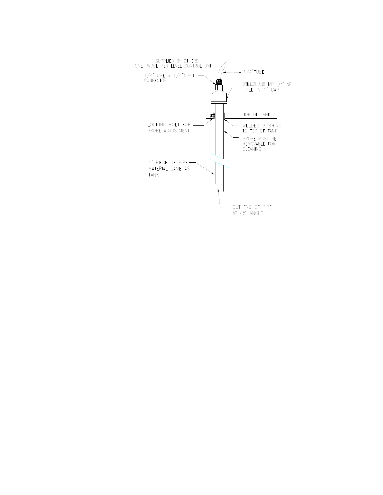
4.2 Air Probe
Supplier
The immersion air probe, is to be supplied by the customer or installation
contractor.
Diameter and Length
The immersion probe shall be at a minimum 1” NPT pipe and be of sufficient
length to extend 6” below the minimum liquid level test point.
Material
The probes should be the same material as the treatment tanks.
Mounting
The air probes may enter from the top or side of the process tank. If
entering from the side the top of the probe should be 6” below that
minimum desired liquid level of the process tank. Installation should ensure
that the probes remain firmly in place and be removable for cleaning if
needed. Ensure that no overhead interferences are present so the probes
may be fully removed vertically.
If the process tank accumulates sludge, the tip of the immersion probe must
be at least 2” above the maximum expected sludge level.
Tubing Runs and Fittings
Tubing (¼ “) is to be run by the installer from each controller to the
respective level control immersion air probe. The tubing shall not be longer
than 15 feet and must not have more than (4) four 90-degree bends. Each
probe must be equipped with a ¼” compression tube fitting for attaching
the tube from the level controller. Tubing is typically copper or
polyethylene. The fittings should be brass or polypropylene when used in
corrosive atmospheres.
9
Level Control Probe Details
4.2 Solenoid Valves
Solenoid valves are electrically activated by the Henkel Level Control installed at
each tank to maintain the desired level. A “Y” strainer shall be installed in the
upstream side of the solenoid valve, and the discharge of the valve should not
protrude below the liquid level of the tank. Valve construction should always be
governed by the liquid passing through it. City water uses brass, De-ionized water
or acidic material requires stainless steel or plastic.

10
5 Operation
5.1 Indicator Light – color and function
Indicator lights table below provides the list of which level control units have the
indicator light. The list is in order of how the indicator lights appear on the level
control panel. Top of the list is top of the panel; bottom of the list is bottom of the
panel. List also shows the which level control units have the indicator light. Only
master level control units have the Master Air Level pressure switch and indicator
light. Standard level control units do not have this feature.
Indicator Label Indicator
Color Indicator ON when 1 PT
Level
2 PT
Level
3 PT
Level
4 PT
Level
Mater Air Low Red no or low air out of
regulator X* X* X* X*
High Level
Alarm Red high level condition X X
Operating Level Green at operating level X X X X
Control Point Amber filling X X X X
Low Level Alarm Red low level condition X X X
Pump Shut
Down Red
pump (or heater)
shut down – server
low level condition
X
* only Master Level Control units have a Master Air Low indicator and internal
pressure switch. Standard Level Controls do not have the Master Air Low
indicator.
Two-point level control unit can be reconfigured as a special for operations
requiring a “Control Point” and “High Level Alarm”. Inquire about this option
with your Henkel representative.
5.2 Adjusting Master Air Pressure Switch
The master air pressure switch changes state based on the set and reset point
adjustment. The pressure switch is adjustable from 8 to 25 psig. The set and reset
points have a fixed difference of 1.8 psig.

11
Adjustment of this pressure switch should be made with the power off and
appropriate lock-out tag-out measures.
The adjustment is made using the adjustment wheel located in the center of the
pressure switch. Approximate pressure setting can be determined by the markings
on the pressure switch calibration scale. Adjustment of the setting is made by
turning the wheel clockwise and counterclockwise.
A more accurate setting of the pressure switch can be made using a multi-meter.
Set the multi-meter to continuity or resistivity and connect the probes to
terminals 1 and 2 of the level control.
Adjust the indicator toward the pressure connection or beyond the desired
pressure set point by turn the adjustment wheel clockwise.
Start with the regulator adjusted to zero. Multi-meter should have
continuity or read 0 ohms.
Adjust the regulator until the pressure gauge reads the desired set point of
the pressure switch.
Turn the adjustment wheel counterclockwise until the switch actuates.
Multi-meter should not have continuity or read open circuit (infinite ohms).
Adjust the regulator to lower the pressure until the switch actuates on from
the decreasing pressure. Multi-meter should have continuity or read 0
ohms.
For a more precise pressure setting; increase and decrease pressure setting
to cycle the pressure switch a few times while making fine adjustments with
the pressure switch wheel.
5.3 Adjusting Regulator Pressure on Master Level Control
Each Master Level Control has a pressure regulator with filter mounted on the side
of the enclosure. A 0…30 psig gauge provides pressure reading of the regulator
outlet to the level controller flow regulators. Outlet pressure must be at least 5 psig
greater than the maximum downstream pressure from the flow regulator.
5.3 Adjusting Flow Regulator
With supply air pressure on adjust the needle valve to produce the desired bubble
rate. The bubble rate is dependent on the volume of air in the system and fluid
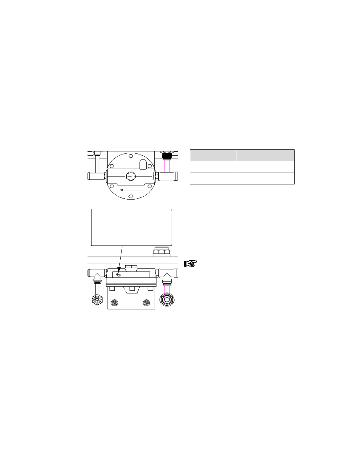
12
level responsiveness. The minimum flow rate of 0.9 SCFH (adjusting screw seated)
can be satisfactory.
If the process tank can have rapid level fluctuations and/or there is much air volume
in the system, the 0.9 SCFH may not have the desired speed of response. Increasing
the bubble rate produces quicker responsiveness to the process tank level changes.
When looking at the level control panel, the flow regulator adjusting screw is
located on the bottom of the flow regulator assembly closest to the outlet. Other
screw next to it is a cleaning wire, furthest from the outlet, is to the right of the
adjusting needle.
It may take a couple of adjustments when
setting the flow regulator to maintain a
minimal bubble rate with an acceptable
response to process tank level changes.
Supply pressure to the flow regulator
must be at least 5 psig greater than the
maximum downstream pressure.
Bubble Rate Adjusting Needle
Increase Counterclockwise
Decrease Clockwise
Adjustment Needle &
Cleaning wire
Bottom of flow regulator
Front of Level Control
Bottom of Level Control

13
5.4 Adjusting Air Differential Pressure Switch for Level
The Henkel Level Controllers have one to four internal differential pressure switches,
depending on model. Adjustment of the differential pressure switch set points are
done the same. Internal springs of the pressure switches may vary for different
process tank level depths.
Consult with Henkel prior to modifying the internal springs. Springs may
need to be replaced in one or more of the pressure switches to achieve
the low or high level operations as required.
Differential pressure switches are not preset for specific process tank level control.
The level settings must be performed on-site to ensure proper operation.
If present, remove the cover from the center of the differential pressure switch
diaphragm housing. Slotted 10-turn adjusting screw will be visible.
Clockwise rotation of the adjusting screw will increase the switch point; raise
the process tank level.
Counterclockwise rotation of the adjusting screw will decrease the switch
point; lower the process tank level.
Before adjusting the differential pressure switches; the level control air probe
must be installed and the bubble rate set.
The process tank should be filled and drained manually during the level set point
adjustment for each differential pressure switch. On recirculating tanks the settings
should be based on the level obtained when the pump is running. The minimum
level setting must be high enough to cover heating coils, and the maximum level
setting must be low enough to prevent overflow when the pump is stopped.
Start adjustments with the differential pressure switch with the lowest fluid
level setting. Work upward towards the pressure switch with the highest
fluid level setting.

14
Adjust the Level Set Point (General Procedure)
1. Turn the adjustment screw clockwise until seated.
2. Turn the adjustment screw counterclockwise 5 complete turns.
3. Fill tank to desired switch level (with recirculating pumps on, if present).
4. Turn adjustment screw slowly until the lamp changes state:
a. If indicator is ON turn the adjustment screw slowly clockwise.
b. If indicator is OFF turn the adjustment screw slowly counterclockwise.
The “Green” and “Amber” indicators are on the Control Point switch.
When one is ON the other is OFF. Adjusting the screw will toggle both
lights.
5. Turn adjustment screw slowly in the opposite direction to change the
indicator state back.
6. Perform number 4 and 5 a couple times stopping with the indicator just
turning OFF. For the Control Point switch, “Green” indicator will be ON and
“Amber” indicator will be OFF.
7. Check switch point by adjust the tank fluid level down and up to change
indicator state. Note tank levels at the indicator state changes.
8. For fine tuning switch point level, repeat steps 3 through 7.
9. Repeat process for next highest process tank level.
5.5 One Point Level Control for Low Level Shut-Off for Drums, Totes, or Day Tanks
One point level control can be used with drums, totes, or day tanks for low level
shutoff of mixers or pumps. The bottom of the probe should be located 1” up from
the bottom of the container. The level control adjustment screw should be turned
full counterclockwise.
Use tubing in place of the immersion air probe when inserting into drums due to
the small drum openings. The tubing needs to be securely fastened to the foot
valve assembly for the chemical feed pump prior to insertion.
15
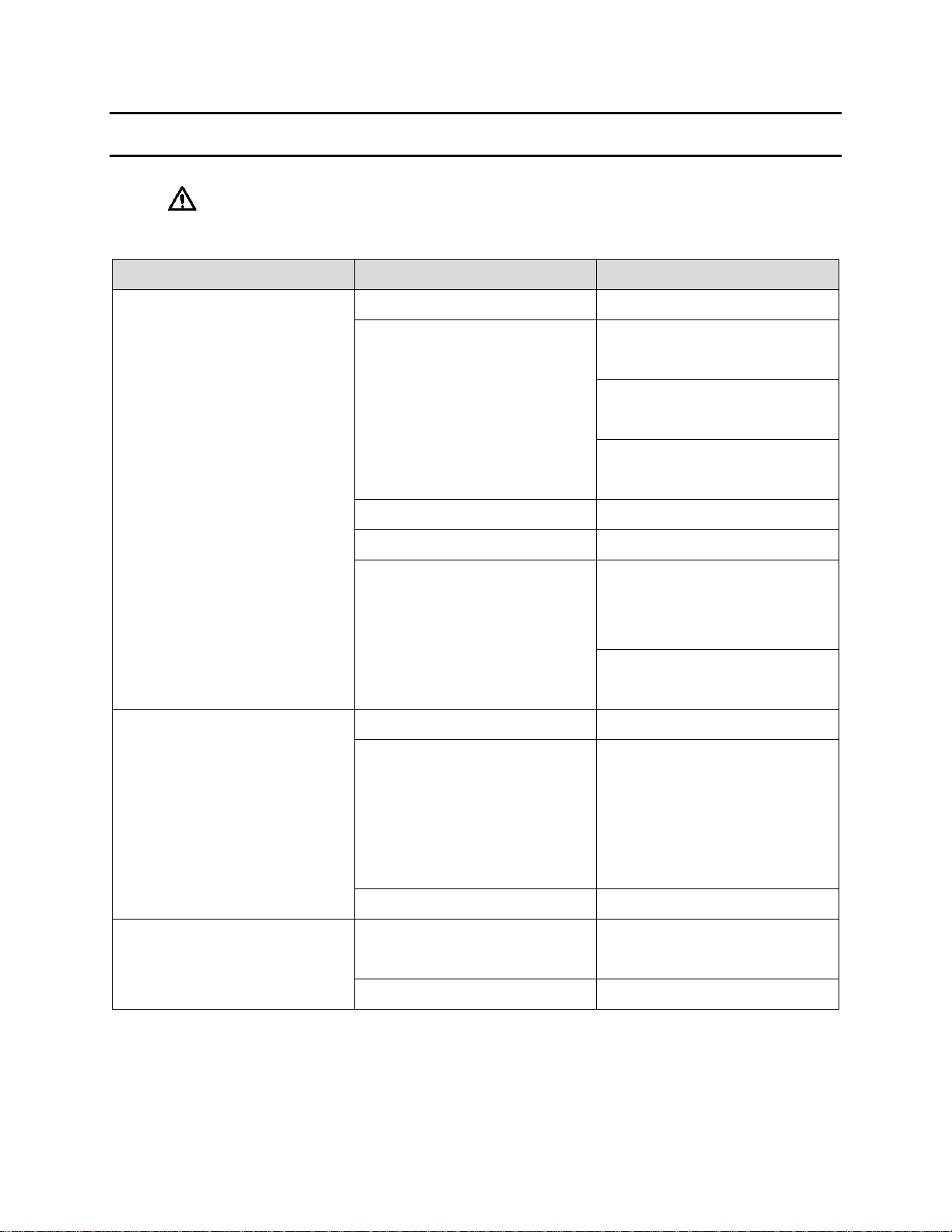
6 Troubleshooting
Before proceeding with any repair or maintenance operation disconnect and turn off
electric and air supplies from the equipment, and discharge any stored energy.
Type of Malfunction Possible Causes Correction
No Bubbles Out of Air Probe
Main Air Supply Off Turn on Main Air Supply
Master Regulator pressure
output too low
Check filter bowl for fluid –
drain and clean
Check filter and clean if
necessary
Adjust Master Regulator
Pressure Higher
Air lines blocked Remove blockage
Air lines collapsed Replace air line
Flow regulator blocked
Verify Master Regulator
pressure setting –
adjust if needed
Clean needle passage of flow
regulator with cleaning wire
Indicators not turning ON
No Power Turn on power
Tripped Circuit Breaker
Inspect loads and wiring for
damage or short circuit –
repair or replace any failed
components before resetting
circuit breaker.
Blown Bulb Replace Bulb
Differential Pressure Switch
not switching
Set Point not set for proper
fluid level Adjust Set Point
Switch Failed Replace Switch

16
7 Care and Maintenance
Before proceeding with any repair or maintenance operation disconnect and turn off
electric and air supplies from the equipment, and discharge any stored energy.
7.1 Master Air Pressure Switch
Ensure proper operation of the pressure switch, periodically cycle the switch by
adjusting the air pressure.
Make sure pressure switch external surfaces are clean and free from foreign matter,
corrosion, or other contamination.
The master pressure switch is not a field repairable item. The entire pressure switch
must be replaced if damaged or not functioning.
Causes of improper operation
Incorrect electrical connection: check leads to switch. Be sure the leads are
properly connected. Switch is marked NO for normally open, NC for
normally closed, and C for common.
Faulty Control Circuit: check the electrical power supply to the switch.
Check for loose or blown fuses, open-circuited or grounded wires, loose
connections at switch. See nameplate for electrical rating and range.
Incorrect pressure: check pressure in system with suitable pressure gauge.
Pressure must be within the range specified on nameplate.
Incorrect Adjustment: check pressure scale to see approximate setting.
Refer to section on Set Point Adjustment of Fixed Deadband Pressure
switch.
External Leakage or Snap Switch Failure: Replace pressure switch, see
Ordering information.
Excessive Vibration or Surges Causing Switch to Operate Undesirably:
Check for pressure fluctuations in system and install pressure surge
suppressor. Check switch mounting and be sure there is no excessive
vibration.
If the operation of the pressure switch cannot be corrected by the above
means, it should be replaced.
This manual suits for next models
8
Table of contents
Other Henkel Control Unit manuals


Popular Control Unit manuals by other brands


M-system
M-system R3-PS3 instruction manual

swissflex
swissflex uni_75RF operating instructions

Audioplex
Audioplex MUSIC MASTER 1 installation manual

Texas Instruments
Texas Instruments ADC12DJ3200 user guide

Nice
Nice mindy TT1N Instructions and warnings for the fitter

TechNexion
TechNexion PICO-IMX8M product manual