Water-Loo Hyper Tough PROJECT CENTER User manual

Ball bearing slides
OPERATOR’S MANUAL
PROJECT CENTER
• The maximum weight for each drawer should be no more than
30 lbs.
• The maximum product weight, including contents, should be no
more than 300 lbs.
F2067 REV A
DANGER is used to indicate a hazardous situation which,
if not avoided, will result in serious injury or death.
WARNING indicates a hazardous situation which,
if not avoided, could result in serious injury or death.
CAUTION is used to indicate a hazardous situation which, if not
avoided, may result in minor injury, moderate injury, or property
damage.
CAUTION: Read and follow all Safety Rules and Operating
Instructions before assembly and rst use of this product.
DANGER
• DO NOT stand on this product. You may fall or cause product
to tip.
• DO NOT open more than one drawer. The product may be-
come unstable and tip.
• DO NOT step in the drawers. You may fall or cause product to
tip.
• DO NOT mount this product on a truck bed or any other mov-
ing object.
• DO NOT move the product prior to closing and locking all the
drawers and chest lid. The drawers could come open and
make the product unstable and tip.
• DO NOT place any objects on top of a closed lid.
LOCATING MODEL # INFORMATION
Model numbers and other information required for service parts is
located on a label on the interior right side of the top most drawer.
• For casters, use high quality bearing grease, (yearly).
• Lubricate the slides with grease or equivalent,(twice yearly.)
• Lubricate lock with graphite, (yearly).
• Periodically the drawer fronts, drawer trim, and other surfaces
should be cleaned with a mild detergent and water.
• Auto wax will preserve the unit’s luster nish. Apply the wax as
to a car. The wax will also help protect the unit against
scratches.
• Grease and oil can be removed with most standard cleaning
uids. For safety, use a nonammable cleaning uid.
• It is recommended that drawer liners be used to protect the n-
ish inside the drawers and to make the drawers easier to clean.
The drawer liners may be cleaned with soap and water.
WARNING
•WEAR SAFETY GLASSES when removing or repositioning
the slides.
• DO NOT pull the unit, push it when moving. Pushing the unit will
prevent serious ankle and foot injuries.
• USE THE BRAKES when not moving this product. This will
prevent the product from rolling.
• DO NOT alter this product in any manner. For example, do not
weld external lockbars or attach electrical equipment.
• Keep the product on level surfaces. The product may become
unstable and tip if stored or moved on an uneven surface.
• BE CAREFUL when closing drawers, the cover or doors.
Remove hands before the cover closes completely.
CAUTION
•This product is not designed to be directly lifted with a fork lift,
or to be towed with any mechanical devices.
• DO NOT exceed the maximum weight capacity for each
drawer or shelf.
• This product should be empty when transporting by vehicle.
Properly secure when transporting.
• DO NOT exceed maximum product weight, including contents.
See Capacities for more information.
• As with all metal products, this product can contain burrs and
sharp edges. Wear protective gloves.
• Use adequate manpower when assembling and moving this
unit. Failure to do so may cause personal injury or product
damage.
Waterloo Industries, 1500 Waterloo Dr., Sedalia, MO 65301
SAFETY
SERVICE PARTS
CAPACITIES
MAINTENANCE
CALL 1-800-833-4405 FOR SERVICE PARTS. Call your local dis-
tributor outside of United States. Refer to Service Parts Drawing
for full listing of Service Parts. Please have model number ready
at time of call.

1/4" Washers (Qty: 7)
#14-10x3/4" Screws (Qty: 7)
Plug (Qty: 1)
Screw
Nut
HARDWARE INCLUDED:
CASTER INSTALLATION
TOOLS REQUIRED:
3/8-in Wrench
7/16-in Wrench
Cross-tip Screwdriver
Items Needed:
1/4 - 20 x 5/8” Screw (Qty: 16)
1/4 - 20 Nut (Qty: 16)
3/8-in Wrench
7/16-in Wrench
PLASTIC TOP INSTALLATION
Items Needed:
#14-10x3/4" Screws (Qty: 7)
1/4" Washers (Qty: 7)
Plug (Qty: 1)
Cross-tip Screwdriver
Process:
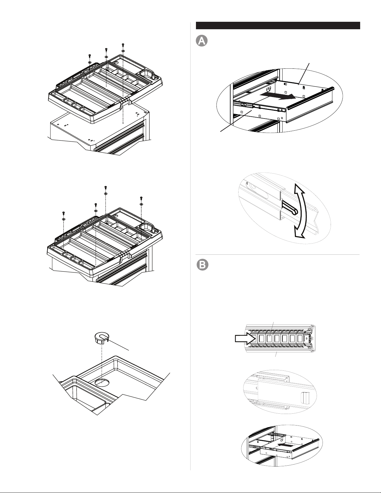
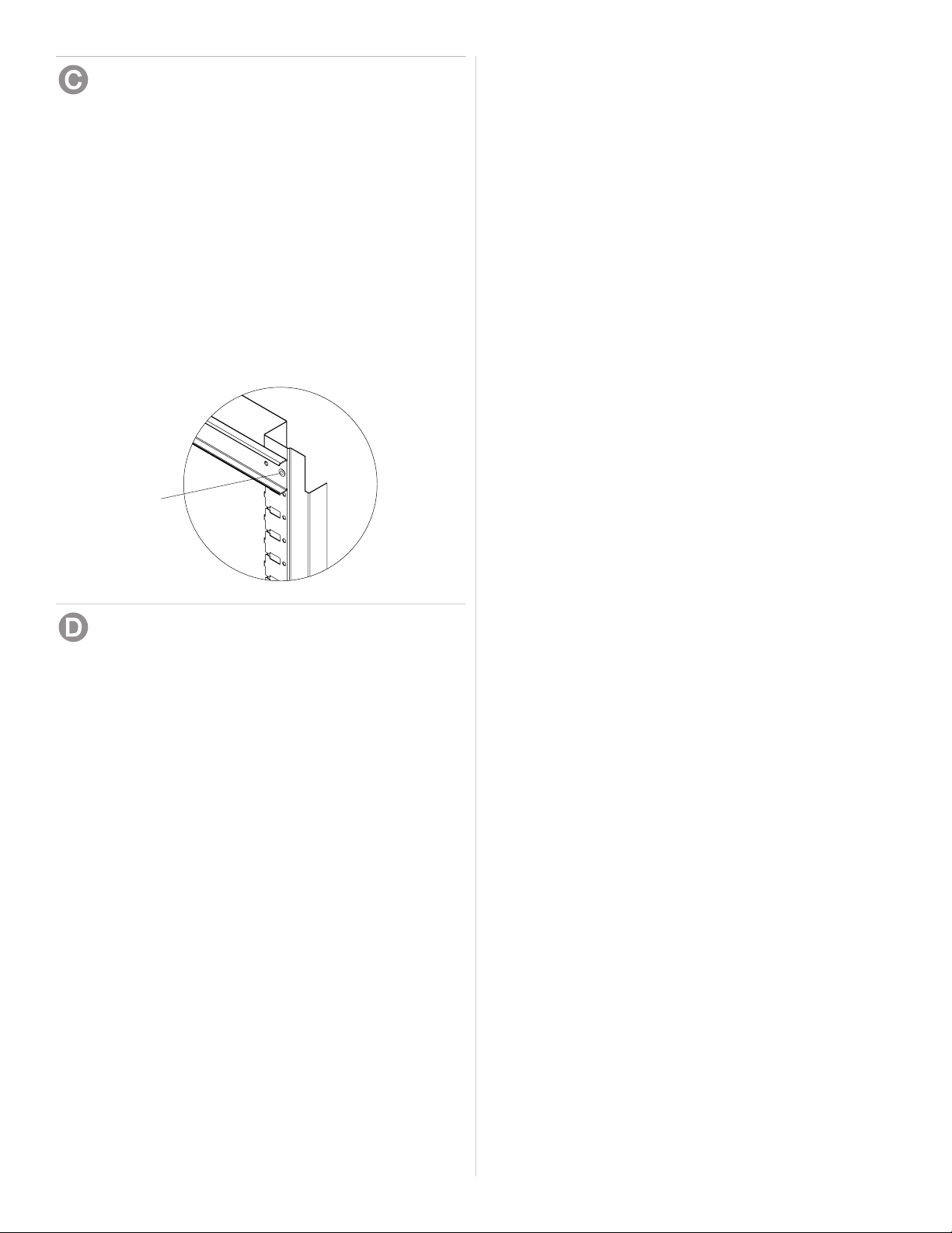
• Slide the two plastic top pieces together and place on the
unit.
Process:
NOTE: Use adequate personnel for this operation.
• Remove the bottom drawer by following the drawer
removal instructions in the operations section.
• Lay the cabinet on its back. Use packaging material to
protect the nish.
• Attach the casters using (4) screws and (4) nuts per
caster. Mount both swivel casters on the same side of
the unit as the side handle.
• Wrench tighten all screws
• Return the unit to its upright position.
• Reinstall bottom drawers.
1/4 - 20 Nut (Qty: 16)
1/4 - 20 x 5/8" Screw (Qty: 16)
2
ASSEMBLY
HARDWARE
Right Release Lever
Left Release Lever
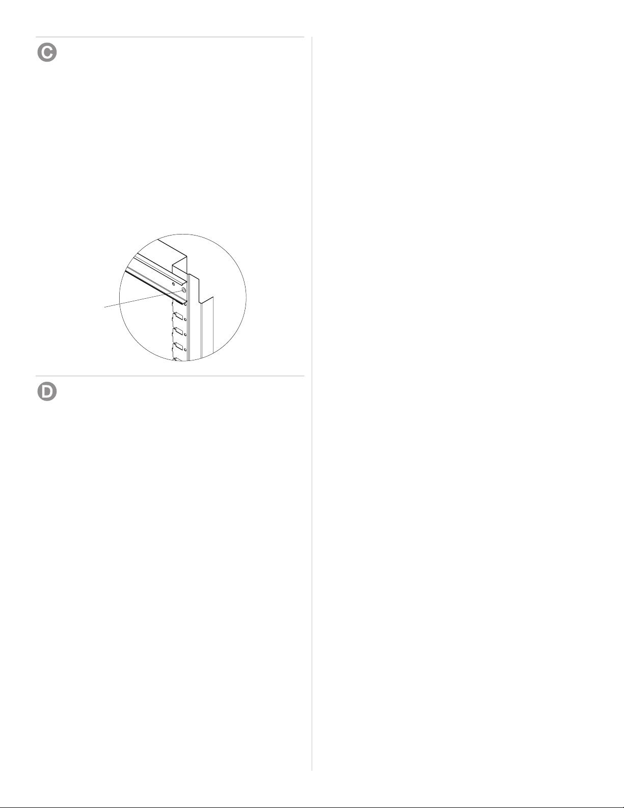
• Empty the drawer.
• Fully extend the drawer.
REMOVING DRAWERS
• Push the lever on the right slide down, lift the lever on
the left side up. Pull out drawer to remove.
• Attach the top to the unit using (3) #14-10x3/4" screws
and (3) 1/4" washers. Be sure the individual tops are
snug against each other.
• Complete top attachment using (4) #14-10x3/4" screws
and (4) 1/4" washers.
• Insert plug into hole in the plastic top. NOTE: To use this
hole for cord management, remove the center portion of
the plug before installing.
• Place wood top on the plastic top.
Remove
3
OPERATION
slide carrier
slide
Ball bearing slide - Pull slides and slide carrier out to fully
extended position (see illustration.) Hold the slide on the
cabinet while aligning it with the slide on drawer. Slightly
insert one side and repeat for the other side. Slowly push
drawer to its fully closed position to engage slide. Open
drawer and reclose to ensure proper operation.
INSTALLING DRAWERS
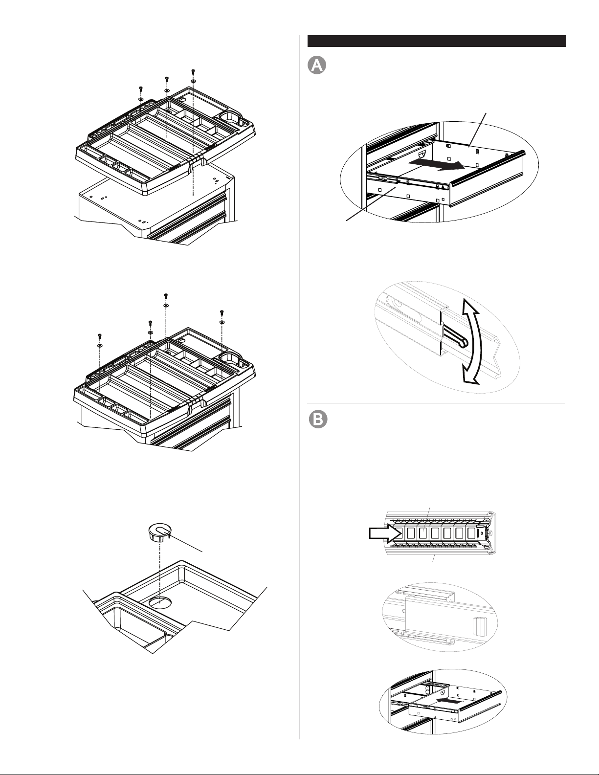
REMOVING AND INSTALLING SLIDES
• To remove the slide from the unit, rst remove the
drawer.
• After removing the drawer check to see if the unit has
rivets located on the front of the slide. To drill out rivets,
use a 5/32-in drill bit. The rivets will need to be replaced
with 5/32-in rivets.
• To reinstall the slide in the appropriate position in the
unit, align front and back lances with mounting holes in
the side of the unit. Pull towards the front of the unit and
downwards until rivet holes in slide line up with holes in
the unit. The rivets will need to be replaced with 5/32-in
rivets.
• For smooth operation, make sure the drawers are
matched with their original slides.
Drill out rivet
DRAWER DETENT
• Easy-gliding ball-bearing drawers are retained by a
detent in order to prevent drawers from opening on their
own. You may have to pull rmly to release the detent
and open drawers.
4

Cojinetes de bolas
MANUAL DE USUARIO
CENTRO DE PROYECTO
• El peso máximo para cada cajón no debe exceder 13.6 kg.
• El peso máximo del producto, incluyendo su contenido, no debe
ser más de 136 kg.
F2067 REV A
PELIGRO se utiliza para indicar una situación peligrosa
que, de no evitarse, resultará en lesiones graves o la muerte.
ADVERTENCIA indica una situación peligrosa que, de no
evitarse, podría producir lesiones graves o la muerte.
PRECAUCIÓN se utiliza para indicar una situación peligrosa que,
de no evitarse, puede derivar en lesiones leves o moderadas, o
en daño a la propiedad.
PRECAUCIÓN: Lea y siga todas las Normas de Seguridad y las
Instrucciones de Funcionamiento antes de ensamblar y de utilizar
por primera vez este producto.
PELIGRO
• NO se ponga de pie sobre esta unidad. Puede caerse u ocasionar
que el producto se vuelque.
• NO abra más de una gaveta. El producto podría quedar inestable
y volcarse.
• NO utilice las gavetas como peldaños. Puede caerse u ocasionar
que el producto se vuelque.
• NO monte este producto en una cama de carro o ninguÌn otro
objeto móvil.
• NO mueva la unidad antes de cerrar y asegurar todas las gavetas
y la tapa del baúl. Las gavetas podrían abrirse y hacer que la
unidad se vuelva inestable y se vuelque.
• NO coloques ningún objeto sobre una tapa cerrada.
UBICACIÓN DE INFORMACIÓN DEL NO. DE MODELO. El
número de modelo y demás información requerida para las pie-
zas de servicio se encuentran en una etiqueta en el lado interior
derecho de la gaveta superior.
• Para las ruedas, utilice grasa para rodamientos de alta calidad
(anualmente).
• Lubrique las guías con grasa o equivalente (dos veces por año).
• Lubrique la cerradura con grato (anualmente).
• Limpie con detergente suave y agua los frontales y los bordes
laterales de los cajones y las demás supercies.
• La cera para automóviles preservará el acabado brilloso de la
unidad. Aplique la cera como lo haría al carro. La cera también
ayudará a proteger la unidad contra raspones.
• La grasa y el aceite pueden retirarse con la mayoría de los
líquidos estándar para limpieza. Por razones de seguridad,
utilice un líquido incombustible para limpieza.
• Se recomienda el uso de revestimientos de cajones para prote-
ger el acabado dentro de los mismos y facilitar su limpieza. Los
revestimientos de cajones pueden limpiarse con agua y jabón.
ADVERTENCIA
•USE GAFAS DE SEGURIDAD al quitar o volver a poner las corred-
eras.
• Si vas a mover la unidad, no la hales, empújala. Empujar la unidad
evitará seria lesiones de tobillos y pies.
• UTILICE LOS FRENOS cuando el producto no esté en movimiento.
Esto impedirá que se deslice.
• NO altere la unidad en modo alguno. Por ejemplo, no suelde las
barras de sujeción externas ni le incorpore equipos eléctricos.
• Mantenga la unidad en supercies niveladas. La unidad puede
tornarse inestable y volcarse si se almacena o se moviliza en una
supercie no nivelada.
• Ten cuidado al cerrar la los cajones, la cubierta o las puertas. Quita
las manos antes de que se cierre la cubierta completamente.
PRECAUCIÓN
•Este producto no está diseñado para ser levantado directamente
con un montacargas, ni para ser remolcado con unidades me-
canizadas.
• No sobrepases el peso máximo para cada cajón o estante.
• Este producto debe estar vacío al ser transportado por algún vehí-
culo. Asegúralo debidamente cuando vayas a transportarlo.
• NO exceda el peso máximo del producto, incluyendo el contenido.
Reérase a las Capacidades para más información.
• Como todos los productos de metal, este producto puede tener
rebabas y bordes losos. Usa guantes protectores al ensamblar.
• Busca la ayuda necesaria al ensamblar y trasladar esta unidad.
No hacerlo puede causar lesiones personales o daños al pro-
ducto.
Waterloo Industries, 1500 Waterloo Dr., Sedalia, MO 65301
SEGURIDAD
PIEZAS DE SERVICIO
CAPACIDAD
MANTENIMIENTO
EN ESTADOS UNIDOS LLAME AL 1-800-833-4405 PARA
PIEZAS DE REPUESTO. Fuera de Estados Unidos llame a
su distribuidor local. Suministre el número de modelo al
comunicarse.

1/4 - Arandella (Cant 7)
#14 - 10 x 3/4 Tornillo (Cant 7)
Retirar (Cant: 1)
Tornillo
Tuerca
PIEZAS INCLUIDAS:
INSTALACION DE LAS RUEDAS
HERRAMIENTAS NECESARIAS:
Llave Inglesa de 3/8 inch
Llave Inglesa de 7/16 inch
Destornillador de Punta en Cruz
Elementos necesarios:
1/4 - 20 x 5/8 Tornillo (Cant: 16)
1/4 - 20 Tuerca (Cant: 16)
Llave Inglesa de 3/8 inch
Llave Inglesa de 7/16 inch
INSTALACIÓN DE LA TAPA DE PLÁSTICO
Elementos necesarios:
#14 - 10 x 3/4 Tornillo (Cant 7)
1/4 - Arandella (Cant 7)
Retirar (Cant: 1)
Destornillador de Punta en Cruz
Proceso:
• Deslice las dos piezas de la tapa de plástico hasta
juntarias y colóquelas sobre la unidad.
Proceso:
NOTA: Use la ayuda de otras personas
para esta operación.
• Quita el cajón inferior siguiendo las instrucciones para
quitar cajones de la sección Operaciones.
• Coloca horizontalmente el gabinete sobre su parte
posterior. Usa el material de empaque para proteger el
acabado.
• Fija las ruedas usando (4) tornillos y (4) tuercas por cada
rueda. Instala ambas ruedas giratorias en el mismo lado
de la unidad que la manija lateral.
• Aprieta con llave todos los tornillos.
• Regresa la unidad a su posición vertical.
• Vuelve a instalar los cajones inferiores.
1/4 - 20 Tuerca (Cant: 16)
1/4 - 20 x 5/8 Tornillo (Cant: 16)
2
ENSAMBLAJE
FERRETERÍA
Palanca de liberación derecha
Palanca de liberación izquierda
• Vacíe la gaveta.
• Abra completamente la gaveta.
REMOCIÓN DE GAVETAS
• Presiona hacia abajo la palanca de la corredera derecha
y levanta la palanca del lado izquierdo.
• Una la tapa con la unidad utilizando (3) tornillos #14-10
x 3/4" y (3) arandelas 1/4". Asegúrese de que las tapas
individuales se ajusten bien la una contra la otra.
• Complete la jación de la tapa utilizando (4) tornillos
#14-10 x 3/4" y (4) arandelas 1/4".
• Inserte la clavija en el agujero del tope de plástico.
NOTA: Para utilizar este agujero en la instalación del
cable, retire la parte central de la clavija antes de realizar
la instalación.
• Coloque la tapa de madera sobre la tapa de plástico.
Retirar
3
FUNCIONAMIENTO
Soporte de las correderas
Corredera
Correderas de rodamientos esféricos - jale hacia afuera
las correderas y el soporte de las correderas hasta que
queden en posición totalmente extendida (ver ilustración).
Sostenga la corredera en el gabinete mientras lo alinea
con la corredera de la gaveta.
INSTALACIÓN DE GAVETAS
INSTALACIÓN Y DESINSTALCIÓN DE CORREDERAS
• Para quitar la corredera de la unidad, primero quite la
gaveta.
• Después de quitar el cajón, comprueba si la unidad tiene
remaches en el frente de la corredera. Para quitar los
remaches con un taladro, usa una broca para taladro
de 5/32 plg. Deberás reemplazar los remaches con
remaches de 5/32 plg.
• Para volver a instalar correctamente la corredera en la
unidad, alinea las lancetas frontales y posteriores con
los oricios de montaje en el lado de la unidad. El tirón
hacia el frente de la unidad y hacia abajo hasta agujeros
de remache en la diapositiva se alinea con agujeros en
la unidad. Deberás reemplazar los remaches con unos
de 5/32 plg.
• Para el buen funcionamiento, asegurese de que los
cajones hacen juego con sus correderas originales.
Saca el remache
con el taladro
TOPE DE CAJÓN
• Los cajones con cojinetes de bola y de fácil desliza-
miento son retenidos por un tope para que los cajones
se abran por sí mismos. Tal vez tengas que halar rme-
mente para liberar el tope y abrir los cajones.
4
Table of contents
Languages:
Other Water-Loo Indoor Furnishing manuals

Popular Indoor Furnishing manuals by other brands

HOPPER STUDIO
HOPPER STUDIO 7190GY415BUY89 Assembly instructions

Hillsdale Furniture
Hillsdale Furniture Kenosha 103703-110944 quick start guide

BOLERO
BOLERO U505 Assembly instructions

Dauphin
Dauphin Stilo owner's manual

wimex
wimex Juist 980070 Assembly instructions

Moduspace
Moduspace Sixth165 Assembly guide


Home Decorators Collection
Home Decorators Collection MARTINGALE 1471410819 Assembly instructions

Invacare
Invacare Softform PREMIER user manual

Home affaire
Home affaire BURANI BU-81 Assembly instructions

DREAMS
DREAMS Addison Bed Double Assembly instructions

Julian Bowen Limited
Julian Bowen Limited Ravello RAV004 Assembly instructions

Forte
Forte NOTE NTEV721L Assembling Instruction