Water Quality Control Systems 2401 Series User manual


2
PROGRAMMING INSTRUCTIONS
SCROLL
UP ARROW
DOWN ARROW
D
Di
is
sp
pl
la
ay
y
Numbers and letters on display in quotation
marks are flashing characters.
Owners Instructions:
The Display should look as follows before you
proceed.
8
8:
:0
00
0
A
AM
M
1
10
00
00
0G
GL
L
The numbers displayed may vary
depending on the model and pervious
programming and time of day.
Press the;SCROLL BUTTON
to locate this display if necessary.
Time Of Day:
PressSCROLL BUTTON
to enter the time of day setting. The display
should read:
S
Se
et
t
"
"8
8:
:0
00
0"
"
A
AM
M
Use the
UP BUTTON
DOWN BUTTON
to program the current time setting.
Holiday Mode:
The holiday mode is used to suspend the
regeneration of the unit during extended
periods on non water usage, The Holiday
mode is deactivated when a flow rate through
the unit of greater that 1.5 gallons per minute
is reached or when it is deactivated by
pressing the:
SCROLL BUTTON
In either case, once a holiday mode has been
activated, the unit will regenerate immediately
upon deactivation. You may advance the
valve through the regeneration manually if
desired (see manual regeneration below).
Manual Regeneration:
To manual regenerate the system the unit
must be in service mode. The display should
read:
8
8:
:0
00
0
A
AM
M
1
10
00
00
0G
GL
L
The numbers displayed may vary
depending on the model and pervious
programming and the time of day.
PressSCROLL BUTTON
SCROLL BUTTON
SCROLL BUTTON
and the display should now read:
R
Re
eg
ge
en
n
i
in
n
9
9
s
se
ec
c
R
Re
eg
ge
en
n
i
in
n
8
8
s
se
ec
c
…
R
Re
eg
ge
en
n
i
in
n
0
0
s
se
ec
c
Seconds will count down from 10 to 0 as
illustrated initiating regeneration. To cancel
the regeneration, scroll past the cycle before
the control counts down to zero. If the control
reaches zero, the system will initiate
regeneration.
To advance the system through regeneration,
press:SCROLL BUTTON
Each time the valve completes indexing to the
next cycle you may continue past each and all
steps in the regeneration cycle until the
control display:

3
8
8:
:0
00
0
A
AM
M
1
10
00
00
0G
GL
L
The numbers displayed may vary
depending on the model and pervious
programming and the time of day.
Delayed Regeneration: The display should
read:
8
8:
:0
00
0
A
AM
M
1
10
00
00
0G
GL
L
The numbers displayed may vary
depending on the model and pervious
programming and the time of day.
Press:SCROLL BUTTON
SCROLL BUTTON
SCROLL BUTTON
SCROLL BUTTON
The control will display:
R
Re
eg
ge
en
n
a
at
t
2
2
0
00
0
A
AM
M
The numbers displayed may vary
depending on the model and pervious
programming and the time of day
Leaving the unit in this mode will initiate a
regeneration at the time indicated on the
display. You must program the time of day
for this time to be accurate.
Installation Programming:
Entering Installers Level:
Press the down arrow and hold in for 5
seconds. The words "System Check" will be
displayed.
S
Sy
ys
st
te
em
m
C
Ch
he
ec
ck
k
Now enter the code to proceed to the
programming options menu below. The code
must be entered within 10 seconds, or the
control will return to the time of day display.
The code is as follows,
DOWN BUTTON
DOWN BUTTON
SCROLL BUTTON
DOWN BUTTON
{Press the DOWN ARROW twice. Then
press the SCROLL button. Finally press the
DOWN ARROW once more}
Use the
SCROLL BUTTON
to advance through the different settings.
Use the
UP BUTTON
DOWN BUTTON
to program the desired setting.
The following is the programming
options menu.
1. Capacity: The control will typically display:
C
Ca
ap
pa
ac
ci
it
ty
y:
:
1
10
00
00
0G
GL
L
The number displayed may vary depending
on the model and pervious programming.
This mode may not be available under
certain conditions
Program the volume of gallons before
regeneration, The value to be entered can
usually be calculated by dividing actual
capacity of the system by the compensated
hardness to be removed. It can be
programmed in a range from 100 to 999,990
gallons.
Use the;
UP BUTTON
DOWN BUTTON
to enter the value of capacity required.
Press the;
SCROLL BUTTON
to move to the nest setting.
R
Re
es
se
et
t
F
Fl
lo
ow
w?
?
"
"N
NO
O"
"
2. Reset flow:
Displays No. If yes is selected the peak flow
rate is set to zero and average volume per
day is set to 25% of capacity. This setting is
entered immediately when the scroll button is
pressed. Its usually not necessary to use this
setting on initial start-up.
Use the;

4
UP BUTTON
DOWN BUTTON
to change the value of this setting.
Press the:
SCROLL BUTTON
to move to the next setting.
3. Reserve:
The unit should now display:
R
Rs
sr
rv
v
"
"V
Va
ar
ri
ia
ab
bl
le
e"
"
OR
R
Rs
sr
rv
v
2
20
00
0G
GL
L
"
"F
Fx
xd
d"
"
The number displayed may vary depending
on the model and pervious programming.
This mode may not be available under
certain conditions
Use the;
UP BUTTON
DOWN BUTTON
to change the value of this setting between
variable and fixed reserves.
3a. Fixed Reserve:
The control must display:
R
Rs
sr
rv
v
2
20
00
0G
GL
L
"
"F
Fx
xd
d"
"
Before proceeding. The default reserve level
is 200 gallons. The reserve value is the
number of gallons of capacity required to
operate during one days usage. In a
residential application it is typically calculated
by multiplying the number of occupants using
the system by an arbitrary daily water usage
{65} To change the amount of reserve, press
SCROLL BUTTON
The unit should display:
R
Rs
sr
rv
v
"
"2
20
00
0"
"G
GL
L
The number displayed may vary depending on the
model and pervious programming. This mode may
not be available under certain conditions.
UP BUTTON
DOWN BUTTON
to change the value of this setting.
Pressing the:
SCROLL BUTTON
again moves you to 4. Time Of
Regeneration below .
3b. Variable Reserve:
The variable reserve is automatically set at
25% of capacity + 75 gallons. This feature
automatically monitors the water used and
fine tunes the reserve on an ongoing basis.
selected or immediate regeneration is
selected in the manufacture mode.
Pressing the:
SCROLL BUTTON
again moves you the next setting.
4. Time Of Regeneration:
This is the time of the day that the unit will
regenerate. The display should look as
follows:
R
Re
eg
ge
en
n
@
@
"
"2
2:
:0
00
0
A
AM
M"
"
The number displayed may vary depending
on the model and pervious programming.
This mode may not be available under
certain conditions
.Use the;
UP BUTTON
DOWN BUTTON
to change the time that the unit will normally
regenerate.
Pressing the:
SCROLL BUTTON
again moves you the next setting
5. Override:
This feature helps keep the unit clean during
extended periods of low water usage.
O
Ov
ve
er
rr
ri
id
de
e:
:
"
"O
OF
FF
F"
"
OR
O
Ov
ve
er
rr
ri
id
de
e:
:
"
"1
12
2"
"
d
da
ay
ys
s
The number displayed may vary depending
on the model and pervious programming.
This mode may not be available under
certain conditions
The unit can be programmed to regenerate
from one to thirty days in the absents of a
volume initiated regeneration. To change or
disable this feature use the:
UP BUTTON
5
DOWN BUTTON
to change the maximum number of days
between regenerations. Setting to off disables
this feature.
Pressing the:
SCROLL BUTTON
again moves you the next setting
The next series of steps are critical to
the valve operation. Only experienced
operators familiar with this units
operation should adjust these settings.
Improper settings of these features may
cause damage to this unit not covered
under warranty. To bypass these setting
press. SCROLL BUTTON
until the display reads
E
Ex
xi
it
t
Then press DOWN BUTTON. The
display should look as follows:
8
8:
:0
00
0
A
AM
M
1
10
00
00
0G
GL
L
Valve Regeneration Set-up
6. Backwash.
The display should be:
B
BA
AC
CK
KW
WA
AS
SH
H:
:
"
"1
10
0"
"
m
mi
in
n
The number displayed may vary depending
on the model and pervious programming.
This mode may not be available under
certain conditions
The backwash time can be programmed from
1 to 99 minutes. The Backwash cycle is used
to remove particulate matter that is
mechanically trapped and restratify in the bed.
Use the:
UP BUTTON
DOWN BUTTON
to change the time that the unit will normally
backwash during regeneration. Pressing the
SCROLL BUTTON
again moves you the next setting
7. Brine and Rinse:
The display should read:
B
BR
RN
N/
/R
RN
NS
S:
:
"
"6
60
0"
"
m
mi
in
n
The number displayed may vary depending
on the model and pervious programming.
This mode may not be available under
certain conditions
The Brine and Rinse cycle is the time when
the brine is drawn into the unit and rinsed to
drain. The Brine and Rinse time can be
programmed form 1 to 99 minutes.
Decreasing the length of this cycle may cause
brine to remain in the bed after regeneration.
Care should be taken when adjusting this
cycle.
Use the:
UP BUTTON
DOWN BUTTON
to change the time that the unit will normally
Brine and Rinse during regeneration. Pressing
the: SCROLL BUTTON
again moves you the next setting.
8. Fill and Rinse:
The display should read:
F
FI
IL
LL
L/
/R
RN
NS
S:
:
"
"5
5"
"
m
mi
in
n
The number displayed may vary depending
on the model and pervious programming.
This mode may not be available under
certain conditions
This Cycle performs two important functions.
1. Controls the amount of water used to
make the brine solution for the next
regeneration.
2. Rinsing and repacking the bed before it is
returned to service.
Adjusting this cycle may result in changing the
amount of brine used during regeneration and
so care should be taken with this adjustment..
The Fill and Rinse time can be programmed
from 1 to 99 minutes. Use the:
UP BUTTON
DOWN BUTTON
to change the time that the unit will normally
Brine and Rinse during regeneration. Pressing
the SCROLL BUTTON
6
again moves you the next setting.
9. Exit:
The display should read:
E
Ex
xi
it
t
The Exit cycle is the confirmation that tells the
unit the changes you have made are to be
accepted by the valve. If you are confident
about the changes you have made then press
the: UP BUTTONOR
DOWN BUTTON
to return to the service mode and burn in the
new settings.
If you want to return to the previous settings
wait for one minute without touching the
control panel and the valve will revert
automatically.
In order for these new settings to become
active, it is necessary to execute a
regeneration. Stepping through
regeneration manually or allowing it to
complete automatically will accomplish this.
Checking the Diagnostics
Diagnostic Mode (Viewing Only)
Press
UP BUTTON
and hold for 5 seconds.
The diagnostics menu will display beginning
with Regen days ago. Press
SCROLL BUTTON
to advance to each diagnostic. If no button is
pressed within 60 seconds, the display will
return back to the time of the day.
Regeneration Days Ago:
Displays how many days ago the unit last
regenerated.
In Service:
Displays how many days the control has been
in service.
Number of Regenerations:
Displays the number of regenerations that
have taken place since the control was
installed.
Total Volume:
Displays the total volume of water used since
installation.
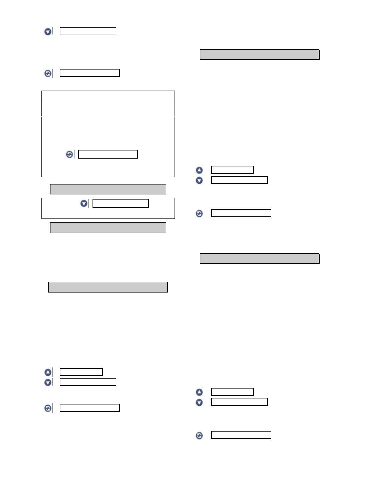
Typical Installation

7
Last Regeneration:
Displays the amount of water used before the
last regeneration.
Peak Flow:
Displays the peak flow rate since the last
regeneration..
Note: This function resets back to zero after
every regeneration.
Average Daily Volume:
Displays the average daily water
consumption.
Capacity/System:
If the control is programmed for Volume, the
display will read CAPACITY along with the
maximum volume of water to be used. When
the control is programmed for hardness, the
display will read SYSTEM along with the
maximum grain capacity of the system.
Hardness:
Displays the amount of hardness programmed
into the control (will not display when control is
programmed for volume).
Reserve:
Displays whether the control is programmed
for fixed or variable reserve.
Note: Will not display when programmed for
immediate regeneration.
Regeneration Time:
Displays the time of day the unit will
regenerate.
Override:
Displays the override mode by reading OFF,
or the number of days programmed into the
control.
Backwash:
Displays the minutes of backwash
programmed into the control
Note: Not applicable on all models.
Brine and Rinse:
Displays the minutes of brine and rinse
programmed into the control.
Fill and Rinse:
Displays the minutes of fill and rinse
programmed into the control.
Note: Not applicable on all models.
Units:
Displays the mode of measurement,
ENGLISH or METRIC.
Meter:
Displays whether the control is programmed
as STANDARD METER, NO METER or
VOLUME/PULSE setting.
Capacity Volume/Hardness:
Displays whether the control is programmed
for a CAPACITY VOLUME or CAPACITY
HARDNESS setting.
Regeneration:
Displays the programmed regeneration type.
DELAYED, IMMEDIATE or
DELAYED/IMMEDIATE.
Valve Type:
Displays the type of valve the factory
programmed into the control.
M P Resets:
Displays how many times the programs have
been reset.
Corrupt Memory:
Manufacturers troubleshooting data.
4000 VTL REV:
Manufacturers troubleshooting data.
8
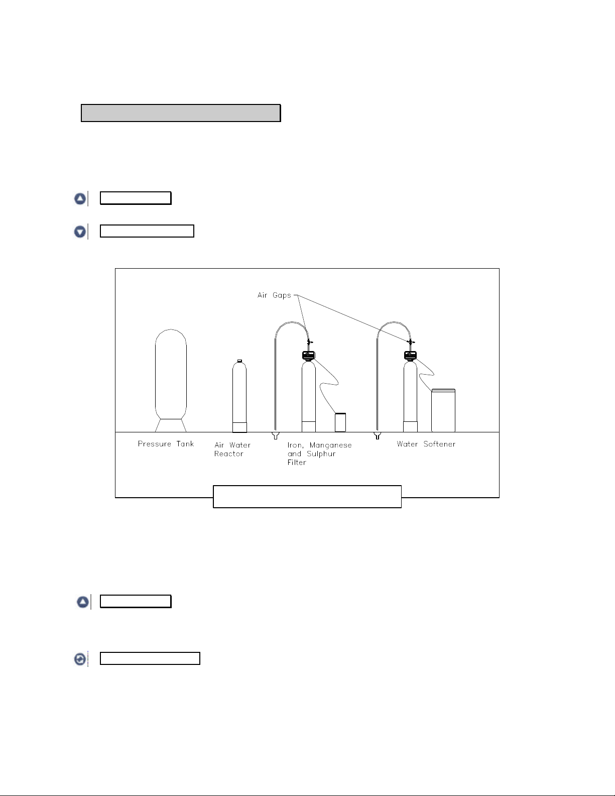
Drain Connection:
Drainpipe should be 1/2"
Hose or larger and
terminated in a manner that
is acceptable to local
codes.
Outlet Connection:
Standard fittings are 3/4"
Male Copper Tubing
Inlet Connection:
Standard fittings are 3/4"
Male Copper Tubing
Safety Overflow:
If the brine tank is located in an
area that could be damaged by a
salt water overflow this fitting
should be connected without
reduction to a gravity flow drain
capable of 1 U.S.G.P.M. minimum
continuous flow.
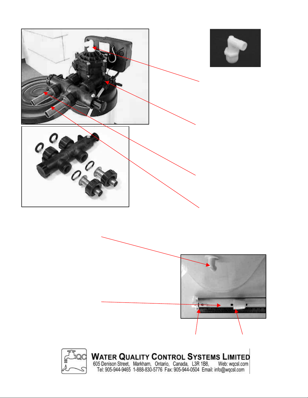
Brine Valve Setting:
( This is a factory setting. Only
adjust when required. )
Measure from the top of the
crown nut (1) to the bottom of the
bell float (2). Consult factory for
settings. (1). Crown Nut (2). Bottom of Bell
Typical Drain Fitting (not included)
Gasket and Fitting position
To Softener
To Plumbing
Brine Connection:
Plastic hose from the brine
tank connects here. Insert
hose into connector to the
depth of the nut and hand
tighten. Tug-test to 15
pounds.
By-Pass Valve Not
Included
Table of contents
Popular Water Dispenser manuals by other brands


Elkay
Elkay VRCGNDWS C Series Installation, care & use manual

BRIO
BRIO CLPOU520UVRO4B Installation and operation manual

MUHLER
MUHLER WD-15 instruction manual

Symphony
Symphony 25CI400A/W Installation, operation and service manual

DOCRILUC
DOCRILUC ENFRIADOR-AGUA USER AND MANTINANCE MANUAL

Elkay
Elkay EMABF8 1B Series Installation, care & use manual

Water Right
Water Right Impression Plus Series Installation instructions & owner's manual

swiftech
swiftech MCW60 installation guide

Primo Water
Primo Water 900115 owner's manual

Fleck
Fleck 9100TS Upflow Service manual

Cosmetal
Cosmetal J Class 30 WG EC Installation, use and maintenance handbook

PUR
PUR PPT711W owner's manual