Water Tec WS1TA User manual

Water Tec of Tucson
• Water Tec of Tucson • www.water-tec.com •
• 4601 S. 3RD Avenue • Tucson, AZ 85714 • (520) 790-1512 • Fax (520) 745-0549 •
WS1TA
Twin‐AlternangWatersoener

MAINCOMPONENTS
YourwatertreatmentsystemisaTwin‐Altpointofentry(POE)systemcomposedoffourcomponents:
A.Thecontrolvalveandcomputerassembly
Thefiberglasstankassembly'sincludingthewatertreatmentmedium
Thebrinetankassemblyincludingsafetyfloat.
Eachoftheseassemblieshasaspecificfunconasdescribedbelow:
ControlValveAssembly…Automacallymonitorswaterusagepaerns,iniatesregeneraonandmovesthevalve
throughthestepsofregeneraon.
MediaTankAssembly…Afiberglassvessels,whichcontainsthewatersoeningmedia,intheproperdiameteranddepth
ofthemediaandevenlydistributesthefeedwaterthroughoutthemediatankassembly.
BrineTankAssembly…Apolyethylenevessel,whichisusedtodissolvesaltandtoholdtheproperamountofbrineforthe
nextregeneraon.Abrinevalvekeepsthecontrolvalvefromdrawingairintothesystem.
STEPSOFOPERATION
Service…Hardwaterflowsdownwardthroughthewatersoeningresinwherethehardnessminerals,calciumandmagnesium,as
wellasdissolvediron,areremovedfromthewaterandarecollectedontheresin.Theamountofresinandthesaltdosage
givesresinacertaincapacityforhardnessandironremoval.
Backwash1…Duringthecyclethewaterflowsupwardthroughtheresinbedandwashescollectedsedimentorotherforeignma‐
terialtothedrain.
BrineandRinse…Thebrinesoluonisdrawnfromthebrinetankandslowlyflowsdownwardthroughtheresincollecngthehard‐
nessandironasitgoes.Thebrinecarriesthehardnessandironwithitandrinsesthemtothedrain.
Backwash2…Sameasbackwash1abovebutofslightlyshorterduraon.
FastRinse…Waterflowsdownwardthroughtheresinandtothedraincarryingwithittheremainingtracesofbrine.
BrineTankRefill…Apredeterminedvolumeofwaterflowsintothebrinetankanddissolvesacalculatedamountofsaltcreang
brineforthenextgeneraon.ThisoccursattheonsetofthenextServicecycle.Besurethatthereisalwaysun‐dissolved
saltremaining.Sincethefrequencyofregeneraonisreasonablyconsistent,aregularaddionofsaltshouldbesched‐
uled.Approximately6"‐8"ofsaltmustbeinbrinetank.Insomecasestheinstallaontechnicianmaydecideapre‐brine
refillmaybeappropriate.Ifsobrinerefillwilloccur2hourspriortoregeneraonandwillresultinminimalwaterinthe
brinetankassemblyduringserviceposion.
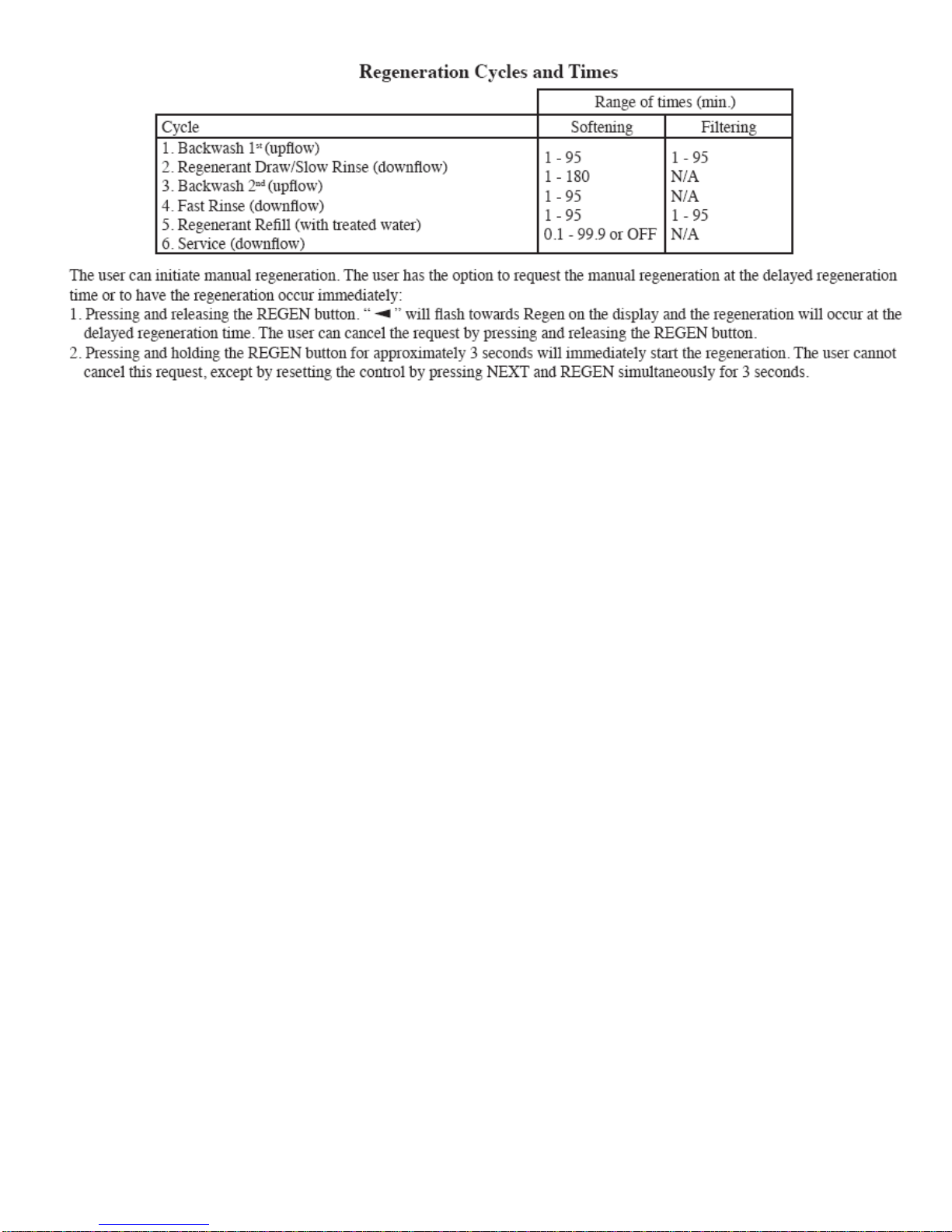
TotalRegeneraonTime(Backwash1throughFastRinse)canbeanywherebetween57and107minutesdependingonseng
madeforcertainwatercondions.

GENERALCAREANDMAINTENANCEINFORMATION
Thefollowingguidelinesarerecommendedforyoutoobtainmaximumefficiencyfromyourwatertreatmentsystem:
ControlValve…Trytokeepfreeofdirtanddebrisbothonvalvebodyandundercover.Nolubricaonisrequired.
BrineTank…Amajorcleaningisrecommendedeverytwoyears.Thisintervalmayneedtobeadjusteddependingonthe
amountofinsolublematerialinthesaltbeingused.
Allowsaltleveltobecomeverylowsothereisliletoremove.Scoopoutun‐dissolvedsalt.
Disconnectandremovebrinevalve.Thereisnopressureorsucononthislineexceptduringaregeneraon.
Removeinternalpartsofbrinetank,ifany.
Cleanbrinetankinteriorwithamildcleaningagent(dishsoap)andrinsethoroughly.
Replacebrinevalveandinternalparts.
Pourfivegallonsofwater(soenedifavailable)intothetank(Addonlytwogallonsifpre‐brinerefilloponisused).
Addsalt.
Replacecover.
Allowtwohoursforconcentratedbrinetobemadebeforenextregeneraon.
Itisrecommendedthat…amanuallyiniatedregeneraonshouldbestartednow.SeeManualRegeneraon.
GENERALINSTALLATION&SERVICECAUTIONS
The control valve, fittings, and/or bypass are designed to accommodate minor plumbing misalignments they are not de-
signed to support the weight of a system or the plumbing.
DonotuseVaseline,oils,otherhydrocarbonlubricants,orsiliconesprayanywhere.Donotusesiliconeonredorclearlip
seals.
Donotusepipedopeorothersealantonthreads.Teflontapemustbeusedonthethreadsofthe1"NPTelbow,its¼"
NPTconnecons,andonthethreadsforthedrainlineconnecon.Teflontapeisnotusedonthenutconneconsorcaps
becauseo‐ringsealsareused.Thenutsandcapsaredesignedtobeunscrewedorghtenedbyhandorwiththespecial
plascServiceWrench,CLV‐V3193(modelswithClackcontrolvalves).Ifnecessary,plierscanbeusedtounscrewthenut
orcap.Donotuseapipewrenchtoghtennutsorcaps.Donotplacescrewdriverinslots,oncaps,and/ortapwitha
hammer.
SITEREQUIREMENTS
‐WaterPressure,20‐125psi‐Currentdrawis0.25amperes
‐WaterTemperature,40º‐110ºF‐A15.powercordisfurnished
‐Thetankshouldbeonafirmlevelsurface ‐Theplug‐intransformerisfordrylocaons
‐Electrical:Usea115/120V,60Hzuninterruptedonly.
outlet.‐Baeriesarenotused.

Thedistancebetweenthedrainandthewatercondionershouldbeasshortaspossible.
Sincesaltmustbeperiodicallyaddedtothebrinetank,thetankshouldbelocatedwhereitiseasilyaccessible.
Donotinstallanywatercondionerwithlessthan10feetofpipingbetweenitsoutletandtheinletofawaterheater.
Donotlocateunitwhereitoritsconnecons(includingthedrainandoverflowlines)willbesubjectedtotemperaturesatorbelow
34ºF.
Theuseofresincleanerinanunventedenclosureisnotrecommended.
Donotinstallequipmentinlocaonsthatwouldreceiverainrun‐offfromroof.
INLET/OUTLETPLUMBING:Connecttoasupplylinedownstreamofoutdoorspigots.Installaninletshutoffvalveandplumbtothe
unitsbypassvalveinletlocatedattherightrearasyoufacetheunit.Whenassemblingtheinstallaon‐fingpackage(inlet
andoutlet),connectthefingtotheplumbingsystemfirstandthenaachthenut,splitringandO‐ring.Heatfromsoldering
orsolventcementswilldamagethenut,splitringorO‐ring.Solderjointsshouldbecoolandsolventcementsshouldbeset
beforeinstallingthenut,splitringandO‐ring.Avoidgengsolderflux,primer,andsolventcementonanypartoftheo‐rings,
splitrings,bypassvalve,orcontrolvalve.Ifthebuilding’selectricalsystemisgroundedtotheplumbinginstallacopper‐
groundingstrapfromtheinlettotheoutletpipe.Plumbingmustbedoneinaccordancewithallapplicablelocalcodes.
DRAINLINE:First,besurethatthedraincanhandlethebackwashflowofthesystem.Solderjointsnearthedrainmustbelocated
priortoconnecngthedrainlineflowcontrolfing.Leaveatleast6"betweenthedrainlineflowcontrolfingandsolder
joints.Failuretodosocouldcauseinteriordamagetotheflowcontrol.Installa3/8"‐1/2"I.D.flexibleplasctubetotheDrain
LineAssemblyordiscardthetubingnutandusethe¾"NPTfingforrigidpipe.Ifthebackwashrateisgreaterthan7gpm,
usea¾"drainline.Rundraintubetoitsdischargepointinaccordancewithplumbingcodes.Payspecialaenontocodesfor
airgapsandantsiphondevices.
9.BRINETANKCONNECTION:Installa3/8"O.D.polyethylenetubefromtheRefillElbowtotheBrineValveinthebrinetank.
10.OVERFLOWLINECONNECTION:
ANOVERFLOWDRAINLINEISRECOMMENDEDANYWHEREABRINEOVERFLOWCOULDDAMAGEFURNISHINGSORTHEBUILD‐
INGSTRUCTURE.
Yoursoenerisequippedwithabrinetanksafetyfloat,whichgreatlyreducesthechanceofanaccidentalbrineoverflow.In
theeventofamalfuncon,anOVERFLOWLINECONNECTIONwilldirectthe“overflow”tothedraininsteadofspillingonthe
floor.Thisbarbtypefingshouldbeonthesideofthecabinetorthebrinetank.
To connect the overflow fitting, locate the hole inside of brine tank. Insert overflow fitting into tank and tighten with plastic
thumbnut from the inside. Attach a length of ½" I.D. tubing (not supplied) to the fitting and run to drain. Do not elevate overflow
line higher than 3" below bottom of overflow fitting. Do not connect this tube into the drain line of the control valve. Overflow
should be a direct, separate line from overflow fitting to drain, sewer, tub, or appropriate outdoor location. Allow an air gap as
per the drain line instructions.
IMPORTANT:
Never insert a drain line directly into a drain, sewer line, or trap. Always allow an air gap between the drain line and the
wastewater to prevent the possibility of sewage being back-siphoned into the water conditioner.

Brinetank
connecon
SecondTankAdaptor
Inter–connector
Inlet Outlet
Drain
***DonotremoveredclipsonBrineTankconneconorDrainconnecon,theseclipsareretainerclipsand
mustbeinstalledforproperoperaon.
InstallaonandStartup
1)Connectsecondtanktomaincontrolvalve.
2)ConnectBrineTank
3)ConnectDrain
4)Connectinlet&Outlet
5)ProgramRegeneraonCapacityingallons(seenextpage)
**AllcontrolprogrammingwiththeexceponoftheRegenCapacityisdoneatthefactory.
6)PerformamanualBackwashandrinseCycleoneachtank.PressandholdREGENbuonfor5secondstostartare‐
generaonletthefirstbackwashcompleteandthenskiptheBrine&RinsecyclebypressingtheRegenbuonwhenmer
startscounngdown.AllowthenextcycletocompletethenskiptheFillCycleforthefirsttank.Repeatthesestepsforthesec‐
ondtank(DONOTskipthefillcycleonthesecondtank).
Thesystemisnowreadyforuse.
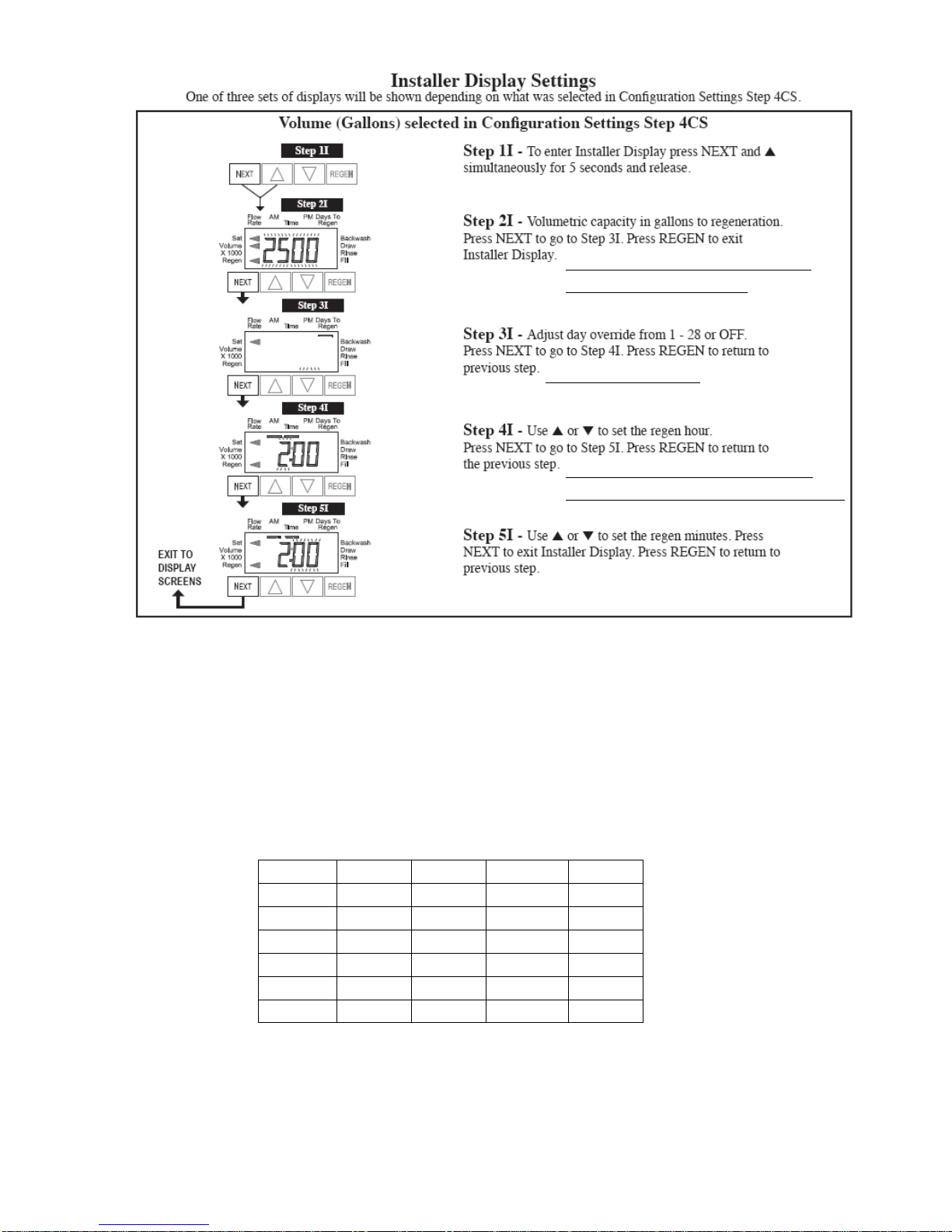
UsecalculaonBELOWtosetcapacity
usingthetestedHARDNESS.
**OFF**Factoryseng
**2:00AM**Theunitwillregenerate
whenthemeterreaches0**Factoryseng
Unitcapacity/hardness=VolumetricCapacity
UnitCapaciesbasedontanksize
OFF
TANKSIZECAPACITY TANKSIZECAPACITY
08X3512,000 12X5248,000
08X4018,000 13X5460,000
09X4824,000 14X6472,000
10X3524,000 16X6596,000
10X4430,000 18X65120,000
10X5436,000 21X62144,000

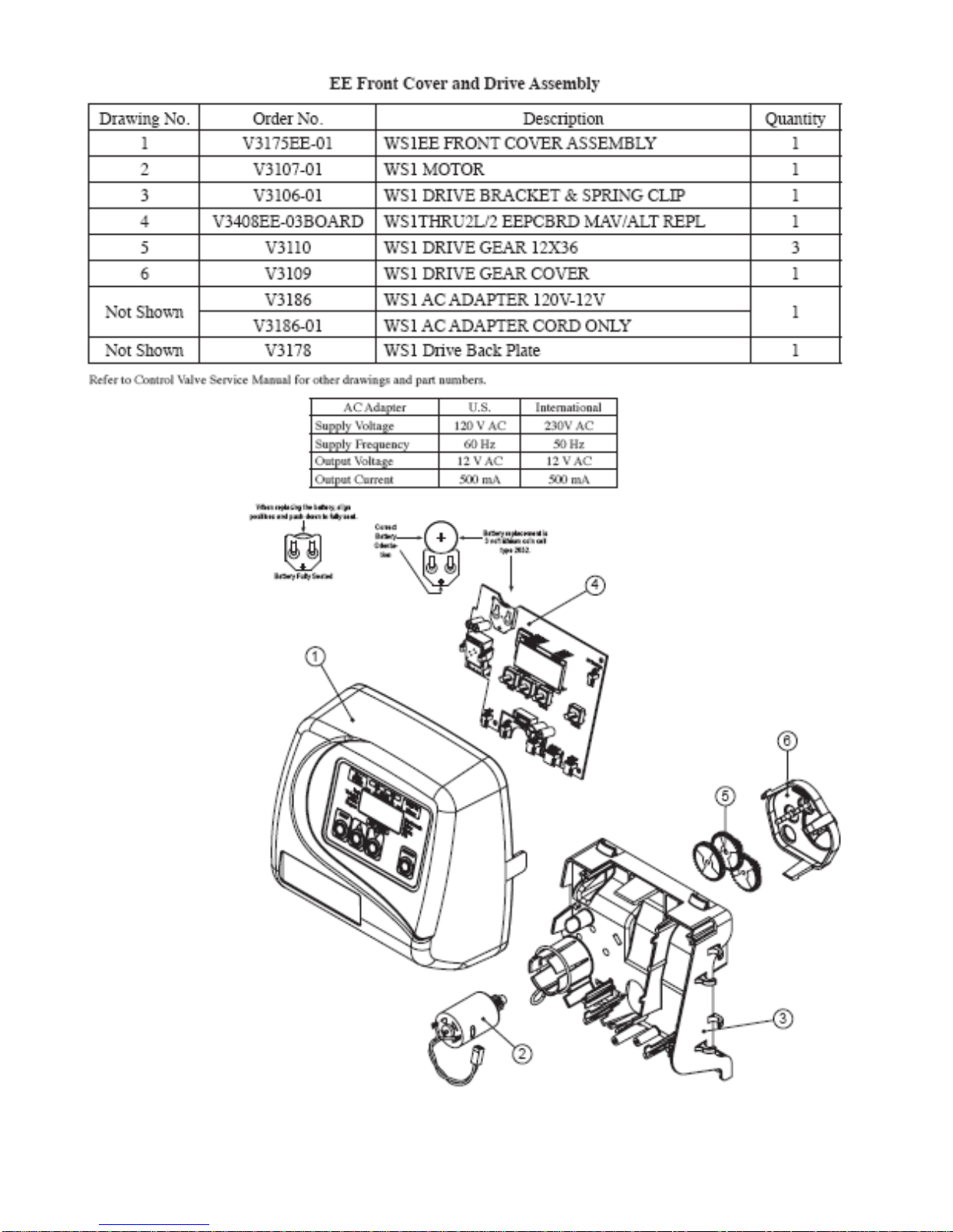

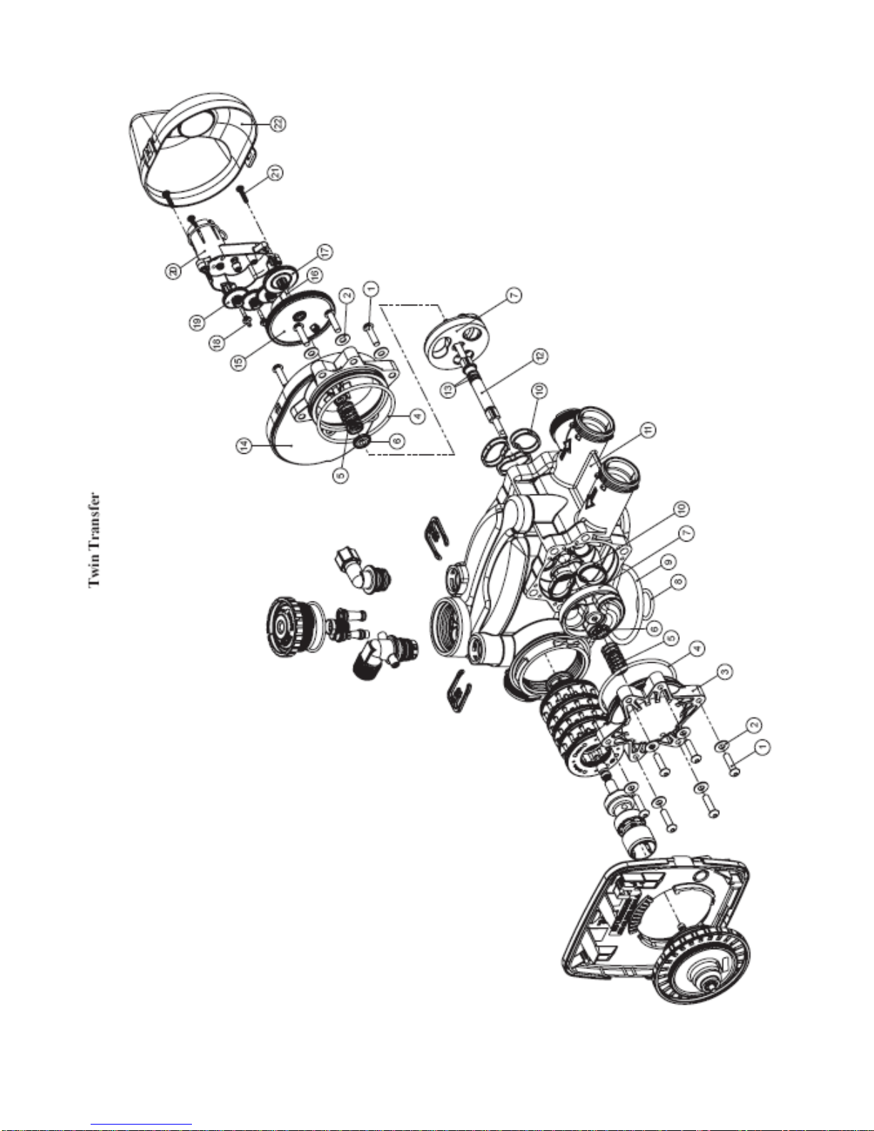


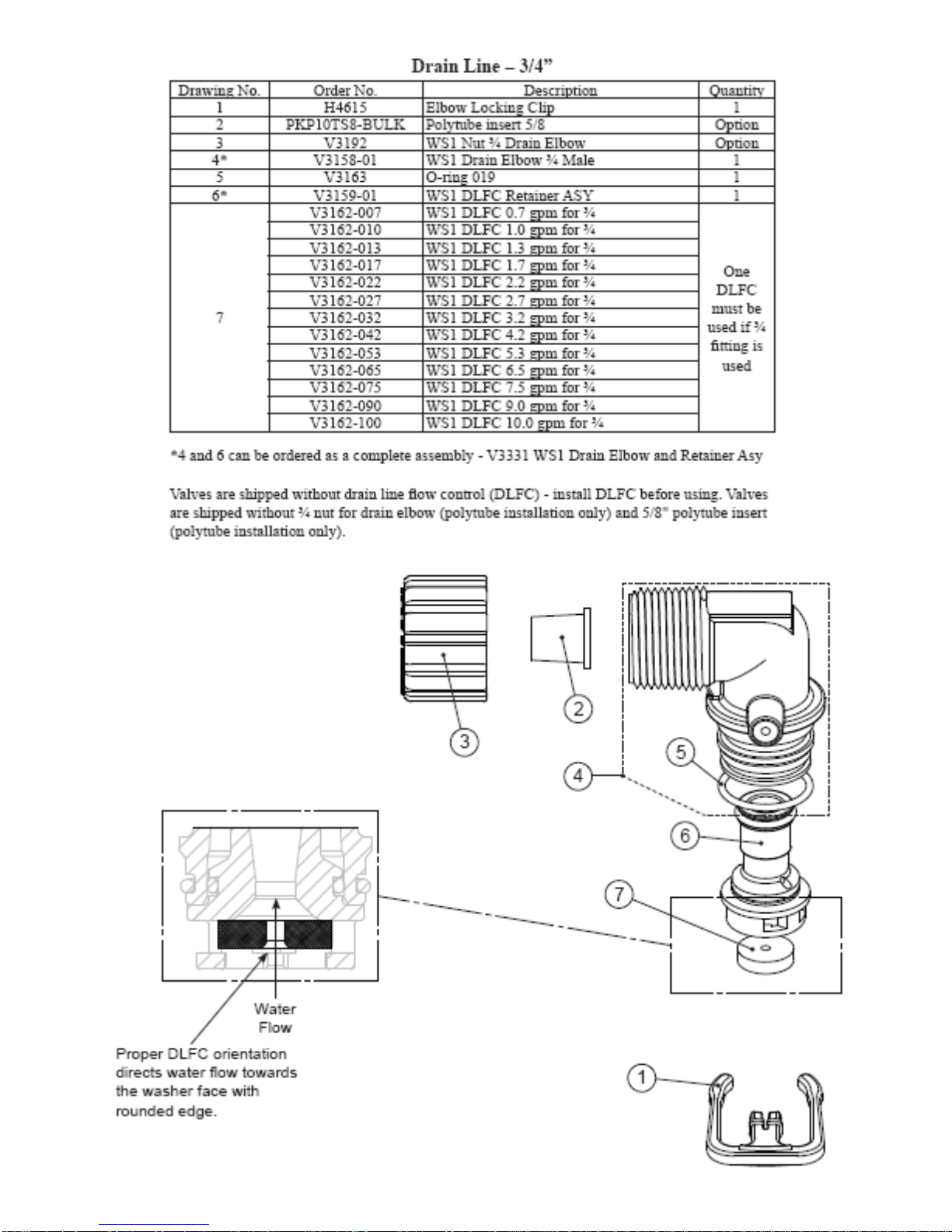
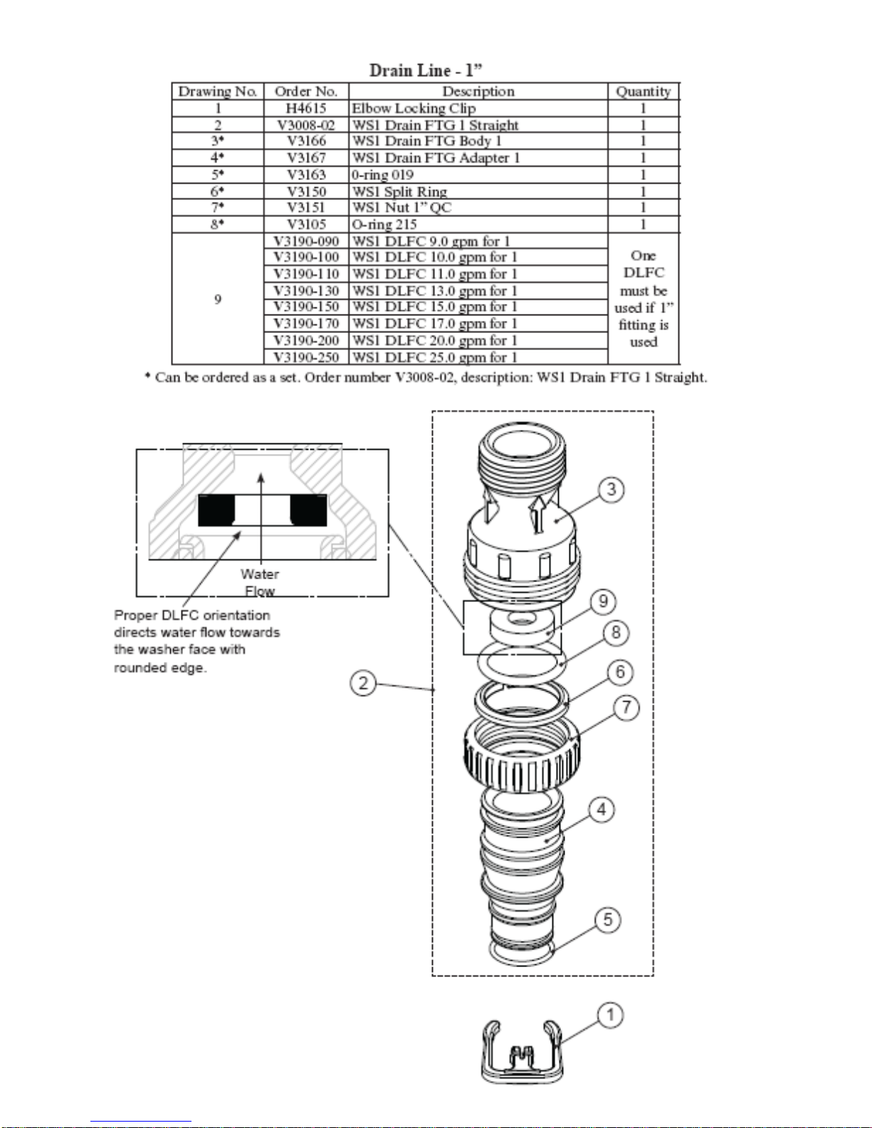
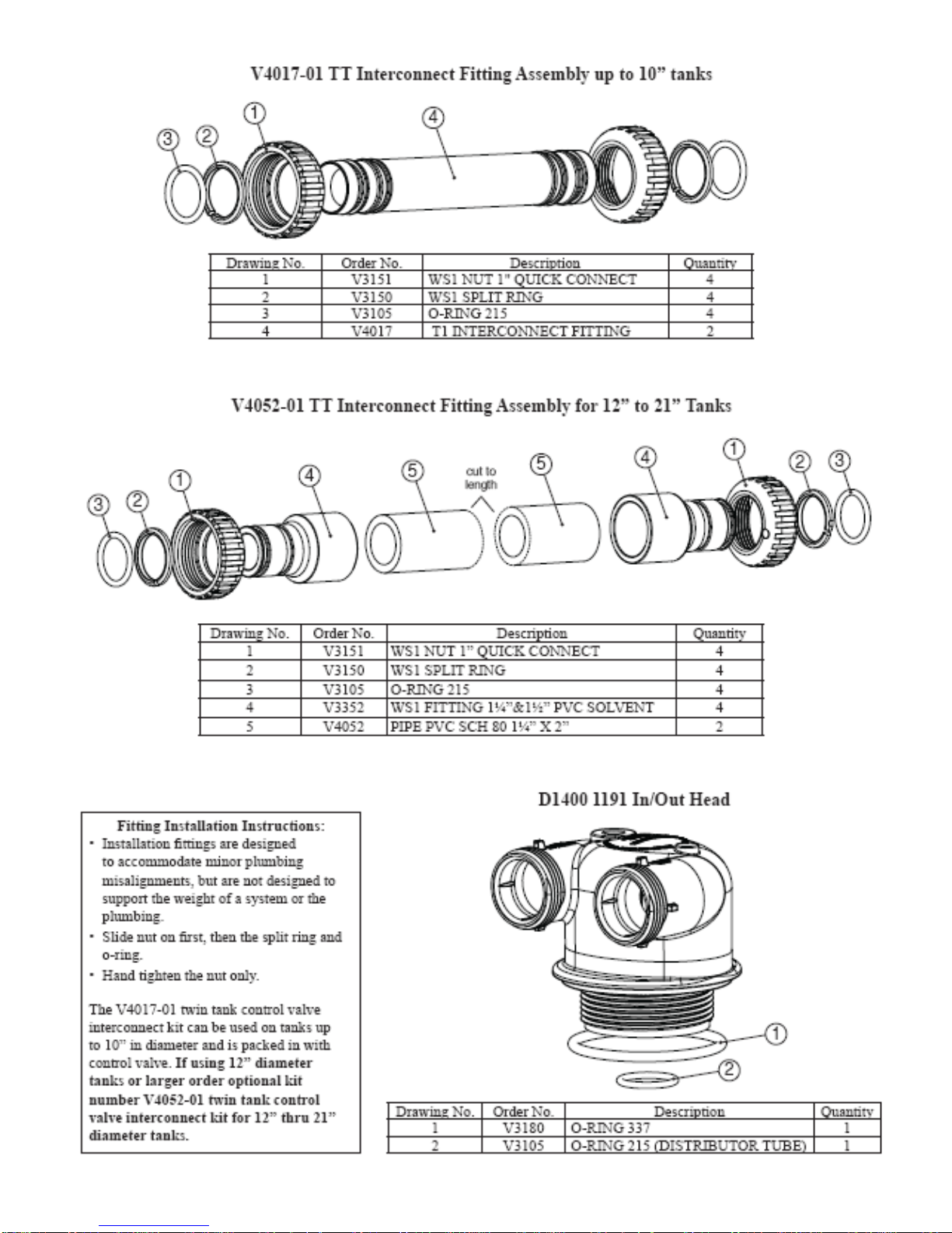

Table of contents
Popular Water Dispenser manuals by other brands


mysoda
mysoda Oasis Evo instruction manual

Water Care
Water Care CareSoft Series Installation instructions & owner's manual

Aquapure
Aquapure AP1610SS Installation and operating instructions

Proficook
Proficook PC-HWS 1145 instruction manual

Eco Pure
Eco Pure EP31 Installation and operation manual

Pure Water
Pure Water 200 Series owner's manual

Halsey Taylor
Halsey Taylor HCRF-ER owner's manual

Kenwood
Kenwood KTLD60X15 Installation instructions manual

SCHLIESSMANN
SCHLIESSMANN AQUA Compact User instructions

Permaflo
Permaflo Purity installation instructions

Wowtech
Wowtech OLK-W-01 Eco Laundry user manual

Hague
Hague HFFE-1054 Owner's manual and installation guide