MURDOCK MFG. • 15125 Proctor Avenue • City of Industry, CA 91746 USA
Phone 800-453-7465 or 626-333-2543 • Fax 626-855-4860 • www.murdockmfg.com
CONTEMPORARY WATER COOLERS
I N S TA L L AT I O N / M A I N T E N A N C E I N S T R U C T I O N S
CONTEMPORARY DRINKING FOUNTAINS
4 of 11
7020-898-001 Revised: 06/01/2023 A
IMPORTANT:
1. Waste P-Trap, Water Supply Service Angle Stop Valve and 2” x 4” Electrical Plug-In Receptacle to be supplied
by others in accordance with local codes. A P-Trap (by others) must be used for the drain connection.
2. Provide 4” minimum clear space on fixture sides to allow for proper ventilation through cabinet louvers.
3. Water supply is 3/8” Outside Diameter copper tube. Waste is 1-1/4” Outside Diameter.
4. Completely flush supply lines of all foreign debris before connecting to fixture. Water cooler designed to not
affect taste, odor, color, or sediment. Optional water filter (WF1 or WF3) is available should any of these
problems arise from the water supply.
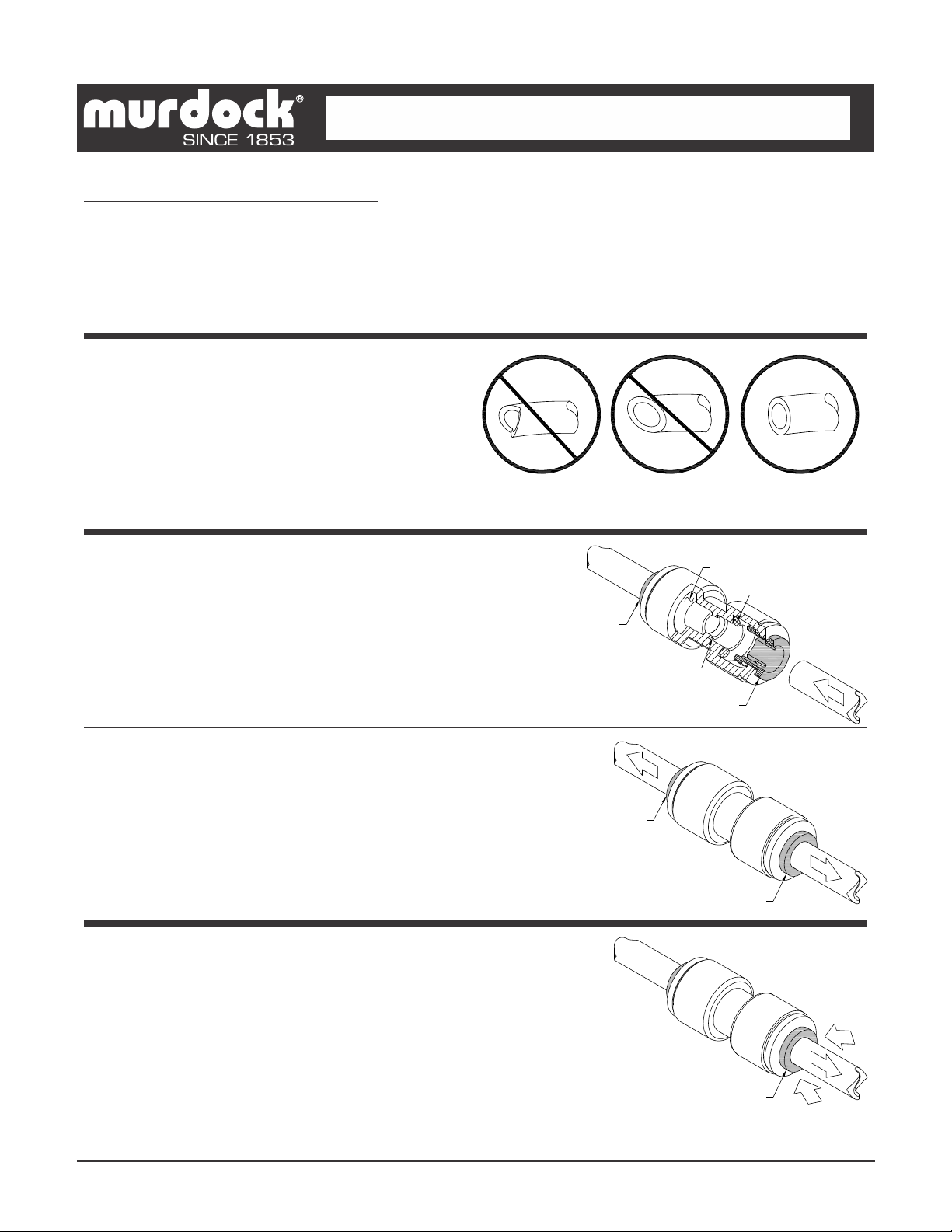
5. Do NOT solder copper tube when inserted into the coupler as damage to the o-ring will result.
6. All burrs must be removed from outside of cut tubes before inserting into coupler or other components.
7. Power supply must be identical in voltage, cycle and phase to that specified on the cooler data plate.
Electrical outlet and furnished power cord with plug must be used to supply power to fixture. Do NOT wire
compressor directly to the power supply.
8. This unit must be grounded per the requirements of applicable electrical codes.
9. Warranty is voided if installation is not made following current Murdock Manufacturing installation
instructions and if components are assembled to the fixture that is not approved by Murdock Manufacturing.
10. Fixture is to operate within a water pressure range of 20 PSIG (138 kPa) to 105 PSIG (724 kPa). Warranty is
void if the unit is allowed to operate outside the range of 20 PSIG (138 kPa) to 105 PSIG (724 kPa). Consult
with UPC and local codes for maximum allowable water pressures.
11. Due to cold waste water, Acorn Engineering recommends that p-trap supplied by installer be insulated to
prevent excessive condensation.
12. Per UPC 609.10- All building water supply systems in which quick acting valves are installed shall be provided
with devices to absorb the hammer caused by high pressure resulting from the quick closing of the valve.
These pressure-absorbing devices shall be approved mechanical devices. Water pressure-absorbing devices
will be installed as close as possible to the quick closing valve.
INSTALLATION:
1. Mount Hanger Brackets to wall horizontally level as shown in Roughing-In and Dimensional Drawing. NOTE:
Adjust height of Bracket if Bubbler outlet height is required to vary from that shown /indicated. Hanger Brackets
MUST be securely anchored to wall with fasteners sufficient to support 3 times the weight of Water Cooler.
NOTE: If wall cannot provide adequate support, order and install Fixture Support Carrier (By others).
NOTE: If replacing a competitors Water Cooler you may be able to use existing mounting bracket
2. Remove the Bottom Cover from the Water Cooler and set aside in a safe place. Save the screws in a secure
location for re-use in later stages of installation.
3. Hang the Water Cooler on the hanger brackets ensuring the bracket tabs engage AND seat in the slots in the
back of the Water Cooler. NOTE: Verify Water Coolers are level, left to right AND front to back from bottom of
unit. CAUTION: The Bubbler stream may be adversely affected if units are not square and level. Bottom of
units and louvers should be used as reference to verify unit is square and plumb.
4. Anchor the Water Cooler to the wall at the lower mounting points of the back panel. Shim lower mounting points
to level unit if necessary.
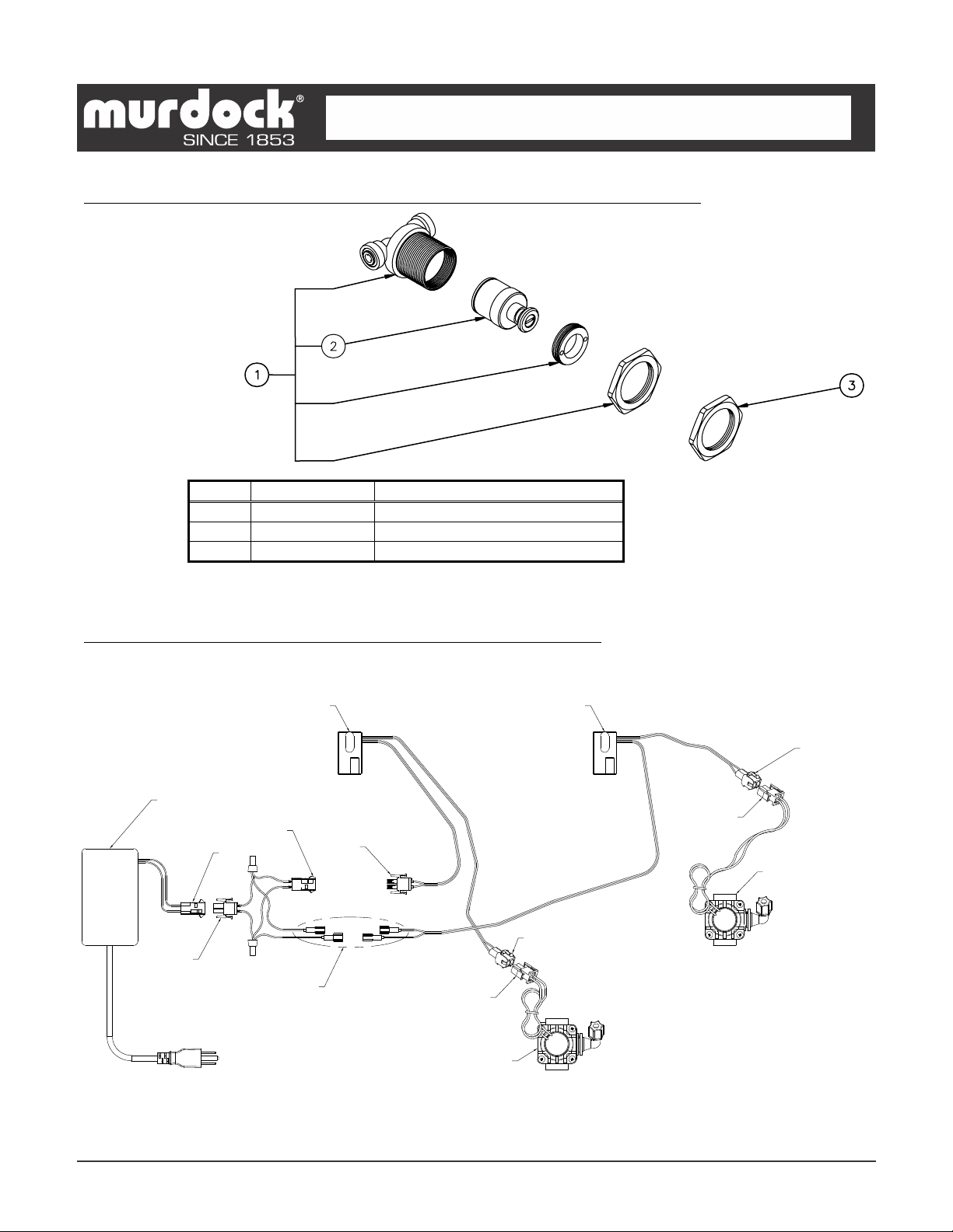
5. Outlet tube from Evaporator has an in-line tee with a tube going to the refrigerated unit's valve and the "TEE"
not connected. Connect the loose Supply Tube from refrigerated unit to the "TEE".
6. Thoroughly flush the 3/8” O.D. supply line and then connect water cooler to water supply angle stop valve (by
others) with supplied 3/8” O.D. copper tube.
7. Make up 1-1/4” O.D. p-trap waste connection. Waste p-trap by others.
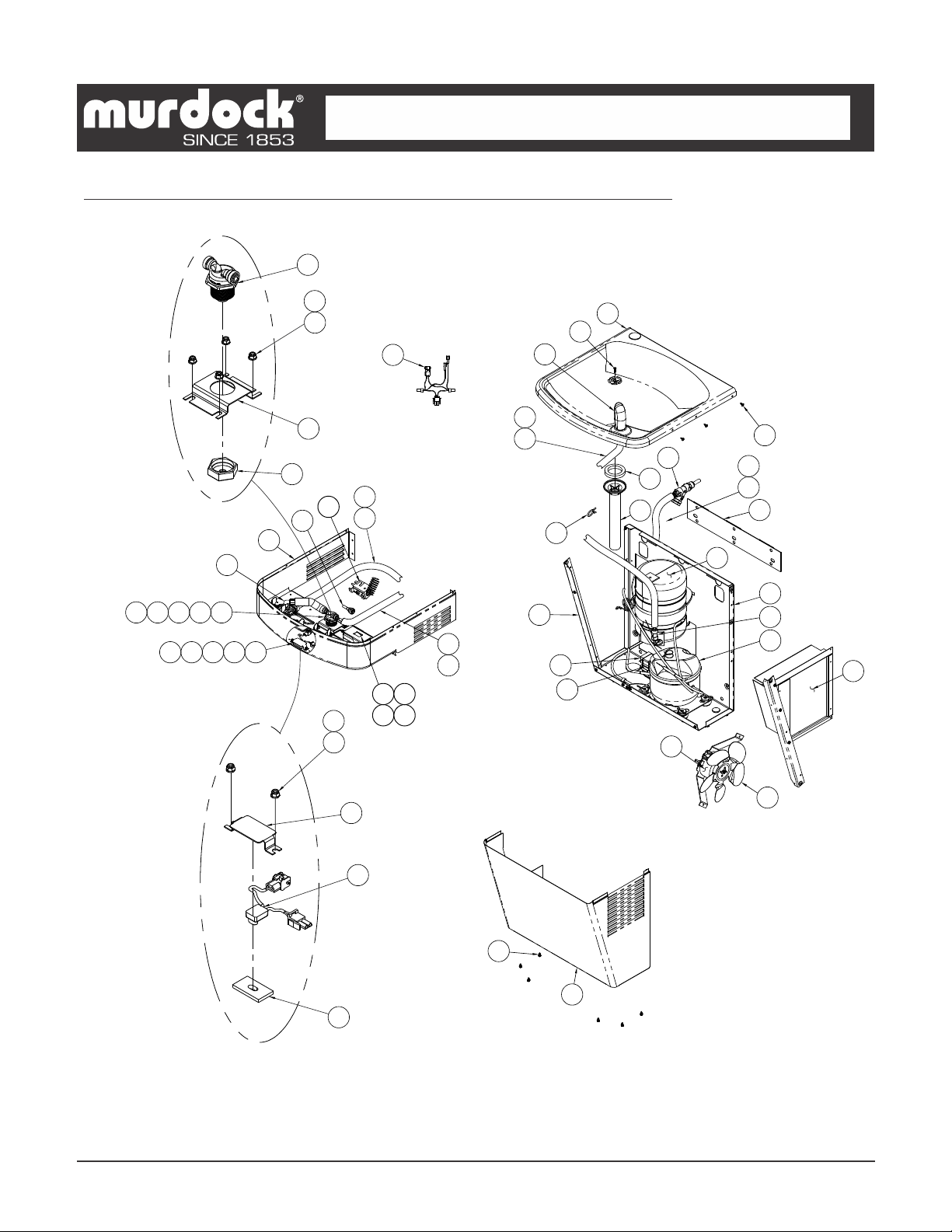
A171.8-UG SERIES REFRIGERATED WALL MOUNTED WATER COOLER INSTALLATION