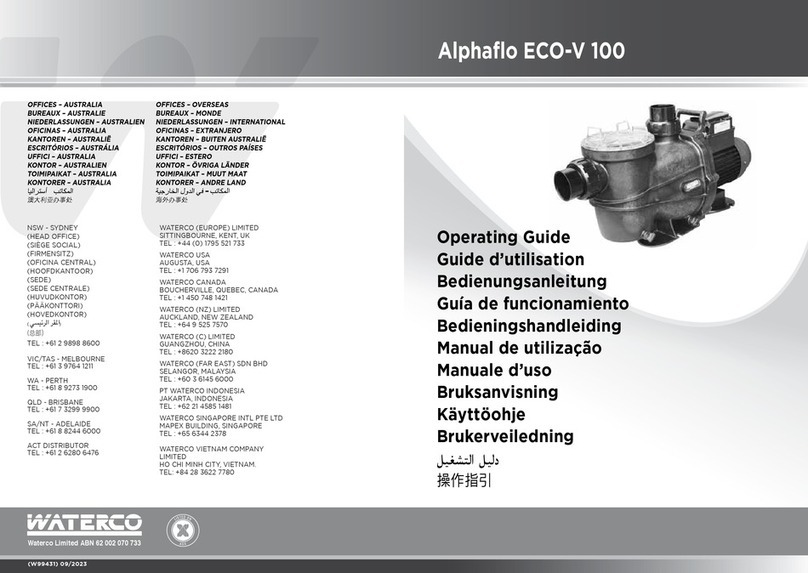
Waterco INFINIUM ECO-V150 User manual

CUSTOMER SERVICE / TECHNICAL SUPPORT
Customer Service and Technical Support, USA
(8:00 A.M. to 5:00 P.M. — Eastern/Pacific Times)
Phone: (706)-793-7291
Fax: (706)-790-5688
Web site
WWW.WATERCO.US
Waterco Limited ABN 62 002 070 733
www.waterco.com
243150A-VS_12/2016
INFINIUM ∞ ECO-V150
Variable Speed Pump
INSTALLATION
AND USER’S GUIDE
NOTICE TO INSTALLER
THIS MANUAL CONTAINS IMPORTANT INFORMATION ABOUT THE INSTALLATION,
OPERATION AND SAFE USE OF THIS PRODUCT. ONCE THE PRODUCT HAS BEEN
INSTALLED THIS MANUAL MUST BE GIVEN TO THE OWNER/OPERATOR OF
THIS EQUIPMENT.
THIS EQUIPMENT MUST BE INSTALLED AND SERVICED BY A QUALIFIED TECHNICIAN.
IMPROPER INSTALLATION CAN CREATE ELECTRICAL HAZARDS WHICH COULD
RESULT IN PROPERTY DAMAGE, SERIOUS INJURY OR DEATH.
IMPROPER INSTALLATION WILL VOID THE WARRANTY.

INFINIUM ∞ ECO-V150 Variable Speed Pump I pg 01
IMPORTANT PUMP AND SAFETY
INSTRUCTIONS ------------------------- x
Pump Overview ------------------------- x
Pump Controller Features ------------- x
General Features ----------------------- x
Installation Instructions ---------------- x
Pump Location ------------------------- x
Pump Mounting ------------------------ x
Plumbing -------------------------------- x
Pipe and Fittings ------------------------ x
ELECTRICAL WIRING INSTALLATION - x
Wiring Diagrams ----------------------- x
Table 1: Mains Connection ------------ x
Table 2: Communication Connection - x
Digital Inputs ---------------------------- x
Operating Instructions ------------------ x
Start-Up & General Operation -------- x
Priming Pump --------------------------- x
Maintenance ----------------------------- x
Storage/Winterization ------------------- x
Programing ------------------------------- x
Introduction ---------------------------- x
Navigation Overview ------------------ x
LED and Function Overview ---------- x
Quick Start Instructions ---------------- x
Quick Start Guide ---------------------- x
(Using the factory default schedule)
Quick Start Guide ----------------------- x
(User-defined custom schedule)
Overview ----------------------------- x
User Interface Key Pad Overview ---- x
Set the Schedule ------------------------ x
Table 3: Factory default schedule ------ x
IMPORTANT PUMP AND SAFETY INSTRUCTIONS
When installing and using this electrical equipment, basic safety precautions should
always be followed, including the following:
•
!
WARNING – Read and follow all instructions in this owner’s manual and on the
equipment. Failure to follow instructions can cause severe injury and/or death.
•
!
WARNING – To reduce the risk of injury, do not permit children to use this product
unless they are closely supervised at all times.
•
!
WARNING – Risk of Electric Shock. Connect only to a branch circuit protected by
a ground-fault circuit-interrupter (GFCI). Contact a qualied electrician if you cannot verify
that the circuit is protected by a GFCI.
•
!
WARNING – The unit must be connected only to a supply circuit that is protected by
a ground-fault circuit-interrupter (GFCI). Such a GFCI should be provided by the installer
and should be tested on a routine basis. To test the GFCI, push the test button. The GFCI
should interrupt power. Push the reset button. Power should be restored. If the GFCI fails
to operate in this manner, the GFCI is defective. If the GFCI interrupts power to the pump
without the test button being pushed, a ground current is owing, indicating the possibility
of an electric shock. Do not use this pump. Disconnect the pump and have the problem
corrected by a qualied service representative before using.
•
!
CAUTION – This pump is for use with permanently-installed pools and may also be
used with hot tubs and spas if so marked. Do not use with storable pools. A permanently-
installed pool is constructed in or on the ground or in a building such that it cannot be
readily disassembled for storage. A storable pool is constructed so that it is capable of
being readily disassembled for storage and reassembled to its original integrity.
• Do not install within an outer enclosure or beneath the skirt of a hot tub or spa.
•
!
WARNING – It is required that licensed electricians do all electrical wiring. Risk of
Electric Shock. Hazardous voltage can shock, burn, cause death or serious property
damage. To reduce the risk of electric shock, do NOT use an extension cord to connect
unit to electric supply. All electrical wiring MUST be in conformance with applicable local
and national codes and regulations. Before working on pump or motor, turn off power
supply to the pump.
THE USE OF UNAPPROVED COVERS OR ALLOWING USE OF THE POOL OR SPA
WHEN COVERS ARE MISSING, CRACKED OR BROKEN CAN RESULT IN BODY OR
LIMB ENTRAPMENT, HAIR ENTANGLE- MENT, BODY ENTRAPMENT, EVISCERATION
AND/OR DEATH.
Schedule Tables ------------------------- x
Running INFINIUM ECO V-150 -------- x
from Keypad
OVERRIDE ------------------------------- x
Schedule Advance ---------------------- x
Key Lockout ----------------------------- x
Motor Pause ----------------------------- x
Temporary Stop with Digital / --------- x
Serial Input
Reset Factory Defaults ----------------- x
Priming ----------------------------------- x
Freeze Protection ----------------------- x
Control with Digital Inputs ------------- x
DIP Switches -------------------------- x
Care and Maintenance ----------------- x
FAULT Status -------------------------- x
Troubleshooting Guide --------------- x
Pump Performance Curves ------------ x
SPECIFICATIONS ----------------------- x
TABLE OF CONTENTS

INFINIUM ∞ ECO-V150 Variable Speed Pump I pg 03
• PUMPS IMPROPERLY SIZED OR INSTALLED OR USED IN APPLICATIONS OTHER THAN
FOR WHICH THE PUMP WAS INTENDED CAN RESULT IN SEVERE PERSONAL INJURY
OR DEATH. THESE RISKS MAY INCLUDE BUT NOT BE LIMITED TO ELECTRIC SHOCK,
FIRE, FLOODING, SUCTION ENTRAPMENT OR SEVERE INJURY OR PROPERTY
DAMAGE CAUSED BY A STRUCTURAL FAILURE OF THE PUMP OR OTHER SYSTEM
COMPONENT.
•
!
WARNING – To reduce the risk of Entrapment Hazards:
• When outlets are small enough to be blocked by a person, a minimum of two
functioning suction outlets per pump must be installed. Suction outlets in the same
plane (i.e. oor or wall), must be installed a minimum of three feet (3’) [0.91 meter]
apart, as measured from near point to near point.
• Dual suction ttings shall be placed in such locations and distances to avoid “dual
blockage” by a user.
• Dual suction ttings shall not be located on seating areas or on the backrest for such
seating areas.
• The maximum system ow rate shall not exceed the values shown in the “Pipe Sizing
Chart” found at the bottom of page 5 of this manual.
• Never use pool or spa if any suction outlet component is damaged, broken, cracked,
missing, or not securely attached.
• Replace damaged, broken, cracked, missing, or not securely attached suction outlet
components immediately.
• In addition to two or more suction outlets per pump installed in accordance with latest
IAF (formerly NSPI) standards and CPSC guidelines, follow all national, state, and local
codes applicable.
• Installation of a vacuum release or vent system, which relieves entrapping suction, is
recommended.
The Virginia Graeme Baker (VGB) Pool and Spa Safety Act creates new requirements for
owners and operators of commercial swimming pools and spas. Commercial pools or
spas constructed on or after December 19, 2008, shall utilize:
• A multiple main drain system without isolation capability with suction outlet covers that
meet ASME/ANSI A112.19.8a Suction Fittings for Use in Swimming Pools, Wading
Pools, Spas, and Hot Tubs and either:
• A safety vacuum release system (SVRS) meeting ASME/ANSI A112.19.17 Manufactured
Safety Vacuum Release systems (SVRS) for Residential and Commercial Swimming
Pool, Spa, Hot Tub, and Wading Pool Suction Systems and/or ASTM F2387
Standard Specication for Manufactured Safety Vacuum Release Systems (SVRS)
for Swimming pools, Spas and Hot Tubs or
• A properly designed and tested suction-limiting vent system or
• An automatic pump shut-off system.
•
!
WARNING – Suction Entrapment Hazard. Suction in suction outlets and/or suction
outlet covers, which are damaged, broken, cracked, missing, or unsecured cause severe
injury and/or death due to the following entrapment hazards:
• Hair Entrapment - Hair can become entangled in suction outlet cover.
• Limb Entrapment - A limb inserted into an opening of a suction outlet sump or suction
outlet cover that is damaged, broken, cracked, missing, or not securely attached can
result in a mechanical bind or swelling of the limb.
• Body Suction Entrapment - A pressure applied to a large portion of the body or limbs
can result in an entrapment.
• Evisceration/ Disembowelment - A negative pressure applied directly to the intestines
through an unprotected suction outlet sump or suction outlet cover which is damaged,
broken, cracked, missing, or unsecured can result in evisceration/disembowelment.
• Mechanical Entrapment - There is potential for jewelry, swimsuits, hair decorations,
ngers, toes, or knuckles to be caught in an opening of a suction outlet cover resulting
in mechanical entrapment.
General Warnings
• Never open the inside of the drive motor enclosure. There is a capacitor bank that holds a
230 VAC charge even when there is no power to the unit.
• The pump is not submersible.
• The pump is capable of high ow rates; use caution when installing and programming to
limit pumps performance potential with old or questionable equipment.
• Code requirements for the electrical connection differ from state to state. Install equipment
in accordance with the current National Electrical Code and all applicable local codes and
ordinances.
• Before servicing the pump; switch OFF power to the pump by disconnecting the main
circuit to the pump.
• This appliance is not intended for use by persons (including children) of reduced physical,
sensory or mental capabilities, or lack of experience and knowledge, unless they have
been given supervision or instruction concerning the use of the appliance by a person
responsible for their safety.
NOTE:
• ALL SUCTION PLUMBING MUST BE INSTALLED IN ACCORDANCE WITH THE LATEST
NATIONAL AND LOCAL CODES, STANDARDS AND GUIDELINES.
• THIS PUMP PRODUCES HIGH LEVELS OF SUCTION AND CREATES A STRONG VACUUM
AT THE MAIN DRAIN AT THE BOTTOM OF THE BODY OF WATER. THIS SUCTION IS SO
STRONG THAT IT CAN TRAP ADULTS OR CHILDREN UNDER WATER IF THEY COME IN
CLOSE PROXIMITY TO A DRAIN OR A LOOSE OR BROKEN DRAIN COVER OR GRATE.

INFINIUM ∞ ECO-V150 Variable Speed Pump I pg 05
Commercial pools and spas constructed prior to December 19, 2008, with a single
submerged suction outlet shall use a suction outlet cover that meets ASME/ANSI
A112.19.8a and either:
• A SVRS meeting ASME/ANSI A112.19.17 and/or ASTM F2387, or
• A properly designed and tested suction-limiting vent system, or
• An automatic pump shut-off system, or
• Disabled submerged outlets, or
• Suction outlets shall be recongured into return inlets.
Pump Overview
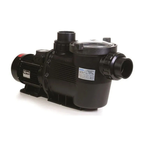
The perfect choice for all types of pools,
the Innium Eco-V Variable Speed Pump as
specically designed to be your best choice
for a variety of in-ground pools.
Thick walled body parts, a heavy duty TEFC
motor, and highly engineered hydraulics
make this rugged and tested design perfect
for any pool, spa, water feature, or fountain.
All pumps from Waterco incorporate
innovative hydraulic engineering that has
been rened for over 40 years.
Compact, rugged, and easy to maintain, the
Innium Eco-V pump will deliver years of
reliable service.
Pump Controller Features
Simple user interface
Motor design reduces noise emissions
UV and rain-proof enclosure
Manual OVERRIDE
High efciency electromechanical motor and
control design
General Features
Extremely quiet operation
Unionized ttings (1.5” and 2”) for simple
replacement
Screw on lid for easy cleaning and
maintenance
Heavy-duty TEFC motor for long life
Integral volute and pot reduce hydraulic
noise
See-through lid permits easy inspection of
strainer basket
Self-priming for quick, easy start-up
IAPMO Listed and tested to UL 1081

INFINIUM ∞ ECO-V150 Variable Speed Pump I pg 07
INSTALLATION INSTRUCTIONS
Pump Location
• Locate pump as close to pool as practical and run suction lines as direct as possible to
reduce friction loss. Suction lines should have continuous slope upward from lowest point
in line. Joints must be tight (but not over-tightened). Suction line diameter must equal or be
larger than the discharge line diameter.
• Though the pump is designed for outdoor use, it is strongly advised to protect the electrical
components from the weather. Select a well-drained area, one that will not ood when it
rains. Do NOT install pump in a damp or non-ventilated location. Keep motor clean.
Pump motors require free circulation of air for cooling.
Pump Mounting
• Install pump on a rm, level base or pad to meet all local and national codes. Fasten pump
to base or pad with screws or bolts to further reduce vibration and stress on pipe or hose
joints. The base MUST be solid, level, rigid, and vibration free.
o Pump mount must:
• Allow pump inlet height to be as close to water level as possible.
• Allow use of short, direct suction pipe (to reduce friction losses).
• Allow for isolation valves in suction and discharge piping.
• Be protected from excess moisture and ooding.
• Allow adequate access for servicing pump and piping.
IMPORTANT NOTES -These instructions contain information for a variety of pump models
and therefore some instructions may not apply to a specic model. All models are intended
for use in swimming pool applications. The pump will function correctly only if it is properly
sized to the specic application and properly installed.
IMPORTANT NOTES -
• All work must be performed by a qualied service professional, and must conform
to all national, state, and local codes.
• No system should allow any higher than 8-ft/sec [2.44 meters/sec] water velocity. It
is recommended that a minimum length of piping, equivalent to 10 pipe diameters,
be used between the pump suction inlet and any plumbing ttings.
Plumbing
• The INFINIUM ECO V-150 comes equipped with external and internal threads. External
threads are designed to be used with the supplied union adapter only and seals with
an O-ring. No thread sealant is used when using the union connectors. When using the
internal threaded ports, This will require a threaded tting and must be supplied by the
installer. This will require the use of Teflon tape to seal threaded connections on molded
plastic components. All plastic ttings must be new or thoroughly cleaned before use.
NOTE - Do NOT use Plumber’s Pipe Dope as it may cause cracking of the plastic
components.
• When applying Teflon tape to plastic threads, wrap the entire threaded portion of the male
tting with one to two layers of tape. Wind the tape clockwise as you face the open end
of the tting, beginning at the end of the tting. The pump suction and outlet ports have
molded-in thread stops. Do NOT attempt to force hose connector fitting past this stop.
It is only necessary to tighten ttings enough to prevent leakage. Tighten tting by hand
and then use a tool to engage tting an additional 1 ½ turns. Use care when using Teon
tape as friction is reduced considerably; DO NOT over-tighten fitting or you may cause
damage. If leaks occur, remove connector, clean off old Teon tape, re-wrap with one to
two additional layers of Teon tape, and re-install connector.
Pipe and Fittings
• Small Pipe and inefcient Fittings restrict ow. For better efciency, we recommend the use
of 2” or larger plumbing. use the fewest possible ttings (but at least two suction outlets).
Avoid ttings that could cause an air trap. Pool and spa ttings MUST conform to the
International Association of Plumbing and Mechanical Ofcials (IAPMO) standards. Use a
non-entrapping suction tting in pool (multiple drains) or double suction (skimmer and main
drain).

INFINIUM ∞ ECO-V150 Variable Speed Pump I pg 09
WARNING!
ELECTRICAL WIRING INSTALLATION
RISK OF ELECTRICAL SHOCK OR ELECTROCUTION. The Innium Eco-V Variable
Speed Pump must be installed by a licensed or certied electrician or a qualied service
professional in accordance with the National Electrical Code and all applicable local codes
and ordinances. Improper installation will create an electrical hazard which could result
in death or serious injury to users, installers, or others due to electrical shock, and may
also cause damage to property.
Always disconnect power to the pump at the circuit breaker before servicing the pump.
Failure to do so could result in death or serious injury to service people, pool users or others
due to electric shock and/or property damage. Read all servicing instructions before working
on the pump.
Wiring Diagrams
1. Be sure all electrical breakers and
switches are turned off before wiring
motor.
2. Insure the supplied power supply
matches the motor Voltage, Cycle,
and Phase found on the motor data
plate. Voltage must be within 10% of
the specied voltage on the data plate.
If they do not match, the motor can
overheat and cause damage.
3. Choose a wire size for the pump in
accordance with the current National
Electrical Code and all applicable local
codes and ordinances. When in doubt
use a heavier gauge (larger diameter)
wire. Heavier gauge will allow the motor
to run cooler and more efcient. Use
copper conductors only.
4. Be sure all electrical connections are
clean and tight.
5. Cut wires to the appropriate length
so they do not overlap or touch when
connected to the terminal board.
6. Prior to connecting the power supply to
the motor, permanently ground the motor
using the ground screw located on the
inside rear of the controller interface, see
figure 3.
7. Use the correct wire size and type
specied by the current National
Electrical Code. Be sure the ground wire
is connected to an electrical service
ground and never ground to a gas line.
8. Prior to connecting the power supply to
the motor, Bond the motor to the pool
structure in accordance with the current
National Electrical Code. UL requires
use of a solid copper bonding conductor
not smaller than 8 AWG. For Canada, a
6 AWG or larger solid copper bonding
conductor is required.
9. Connect the wire from the accessible
wire connector on the motor to all metal
parts of the swimming pool, spa, or
hot tub structure and to all electrical
equipment, metal conduit, and metal
piping within 5 feet (1.5 M) of the inside
walls of the swimming pool, spa, or hot
tub.
10. The pump should be permanently
connected to a GFCI circuit breaker, use
a dedicated circuit breaker that has no
other electrical loads.
11. Connect the pump permanently to a
circuit. Make sure no other lights or
appliances are on the same circuit.
Note: When the pump is started and stopped
by removing power with a relay or timer, a
two-pole device should be used to apply
and remove power to both POWER LINE
TERMINALS.
!
WARNING
Power should be turned off when installing, servicing, or repairing electrical components.
Observe all warning notices posted on the existing equipment, INFINIUM ECO V-150 and in
these installation instructions.
Pin # Wire Color Description
L1 Black Hot 1
L2 Red or White Hot 2
Green screw Green Earth
Table 1 : Mains Connection
Pin # Wire Color Description
J201 - 1 Red +12V
J201 - 2 Black A
J201 - 3 Yellow B
J201 - 4 Green COM
Table 2 : Communication Connection
Figure 3 : Mains Connection Diagram
L2
(RED OR WHITE)
L1
(BLACK)
EARTH
EARTH
208-230V POWER
SOURCE

INFINIUM ∞ ECO-V150 Variable Speed Pump I pg 11
Operating Instructions
Start-Up & General Operation
Digital Inputs
!
WARNING
Access to these terminals is in close proximity to the mains connectors which carry line
voltage capable of causing personal injury or damaging the equipment if contact is made.
Power should be turned off when accessing this area.
Figure 4 : Wiring Diagram for Digital Inputs
Figure 5 : Digital Inputs connector
!
CAUTION - Before removing strainer cover:
• STOP PUMP before proceeding.
• CLOSE VALVES in suction and outlet pipes.
• RELEASE ALL PRESSURE from pump and piping system using filter
manual air relief valve. See filter owner’s manual for more detail.
!
CAUTION - All suction and discharge valves MUST be OPEN, as well as filter air
relief valve (if available) on filter, when starting the circulating pump system. Failure to
do so could result in severe personal injury.
NEVER OPERATE THE PUMP WITHOUT WATER.
Running pump dry may damage seals, causing leakage, flooding, and voids warranty.
DO NOT add chemicals to pool/spa system directly in front of pump suction or in
Pump Strainer housing. Adding undiluted chemicals may damage pump and voids
warranty.
Priming Pump
• Remove Strainer cover by turning the lid Counter Clockwise.
• Fill strainer housing with water up to the suction pipe level.
• If water source is higher than the pump, pump will prime itself when suction and
outlet valves are opened. Always verify the strainer housing is full of water. If water
source is lower than the pump, the pump must be filled.
• Clean and lubricate strainer cover O-ring with “Silicone based O-ring Lube” each
time it is removed. Inspect O-ring and re-install on strainer cover.
• Replace strainer cover on strainer housing; turn clockwise to tighten cover. NOTE -
Tighten Lid by hand only (no wrenches).
• Turn on power and wait for pump to prime, which may take up to five (5) minutes.
Priming time will depend on vertical length of suction lift and horizontal length of
suction pipe. If pump does NOT prime within five minutes, stop motor and determine
cause. Be sure all suction and discharge valves are open when pump is running. See
Troubleshooting Guide.
!
ATTENTION – Wait five (5) seconds before re-starting pump. Failure to do so
may cause reverse rotation of motor and consequent serious pump damage.
• Close filter manual air relief valve after pump is primed.
EXTERNAL SUPPLY
Automation System or
Solar System Controller
UI DIGITAL
INPUT CONNECTOR
J202
Vac or
VDC
GND
STEP 1
(pin 1)
STEP 2
(pin 2)
STEP 3
(pin 3)
OVER RIDE
(pin 4)
COMMON
(pin 5)
External Supply Range:
18-30V AC (24V AC +/- 20%)
9-30V DC (12/24V DC +/- 20%)

INFINIUM ∞ ECO-V150 Variable Speed Pump I pg 13
Programing
Introduction
The INFINIUM ECO V-150 uses a premium efciency variable speed motor that provides
tremendous program exibility in terms of motor speed and time settings. The variable speed
motor is intended to enable running at the lowest speeds needed to maintain a sanitary
environment, which in turn minimizes energy consumption. Pool size, the presence of additional
water features, chemicals used to maintain sanitary conditions, and environmental factors will
impact optimal programming necessary to maximize energy conservation.
The integrated electronics interface controls the speed settings as well as the run durations.
The INFINIUM ECO V-150 can run at speeds ranging between 600 and 3450 RPM and is rated
for 208-230 Vrms at an input frequency of 60 Hz.
Navigation Overview
>+, - Increases/decreases selected value
>Pressing any key following a change accepts the current value displayed inside the setting
Note: The START button must be pressed for the INFINIUM ECO V-150 to operate. The START
LED will illuminate after the button has been pressed indicating the INFINIUM ECO V-150 is
capable of operating. Pressing the stop button will turn off the START LED and stop the motor
if running
Maintenance
• Clean strainer basket regularly. Do NOT strike basket to clean. Inspect strainer cover
gasket regularly and replace as necessary.
• Waterco pumps have self-lubricating motor bearings and shaft seals. No lubrication
is necessary.
• Keep motor clean. Insure air vents are free from obstruction to avoid damage. Do
NOT use water to hose off motor.
• Occasionally, shaft seals must be replaced, due to wear or damage. Replace with
genuine Waterco seal assembly kit.
Storage/Winterization
!
!
WARNING – Separation Hazard. Do not purge the system with compressed air.
Purging the system with compressed air can cause components to explode, with risk
of severe injury or death to anyone nearby. Use only a low pressure (below 5 PSI),
high volume blower when air purging the pump, filter, or piping.
!
!
ATTENTION – Allowing the pump to freeze will void the warranty.
!
!
ATTENTION – Use ONLY propylene glycol as antifreeze in your pool/spa system.
Propylene glycol is non- toxic and will not damage plastic system components; other
anti-freezes are highly toxic and may damage plastic components in the system.
!
!
WARNING – To avoid dangerous or fatal electrical shock hazard, turn OFF power
to motor before draining pump. Failure to disconnect power may result in serious
personal injury or death.
Storing Pump For Winterization
• Drain water level below all inlets to the pool.
• Drain all water from pump and piping when expecting freezing temperatures or when
storing pump for a long time (see instructions below).
• Remove drain plugs from bottom of strainer body, and remove strainer cover from
strainer housing.
• Disconnect pump from mounting pad, wiring system (after power has been turned
OFF), and piping system.
• Keep motor dry and covered during storage. To avoid condensation/corrosion
problems, do NOT cover or wrap pump with plastic film or bags.
Figure 1 : V-Green 165 User Interface Button Descriptions

INFINIUM ∞ ECO-V150 Variable Speed Pump I pg 15
INFINIUM ECO V-150 Features
• Simple user interface
• Digital inputs for compatibility with pool automation systems
• Motor design reduces noise emissions
• UV and rain-proof enclosure
• Freeze Protection
• Manual OVERRIDE
• High efciency electromechanical motor and control design
LED and Function Overview
Key for LEDs
X Solid ON Indication
* Blinking @ 1 sec
** Alternates between DURATION and SPEED
# Blink for three times @ 1 sec
Power START FAULT STEP1 STEP2 STEP3 OVERRIDE SPEED
SETTING
DURATION
SETTING BARGRAPH
Power On X
Keypad Functions
Step1 X X X * * * * * *
Step2 X X X * * * * * *
Step3 X X X * * * * * *
Override X X X * * * * * *
Keypad lock X * * *
Keypad Unlock X X X X
Schedule Advance X * X X
Restore Default
settings X # (All LED)
Motor pause X * * X X
Temporary stop X * (0 RPM)
Digital Input Functions
DI1 ON X * X X
DI2 ON X * X X
DI3 ON X * X X
DI4 ON X * X X
Serial Communication Functions
Serial Communication X *
Motor spinning X * X
Freeze Protection
Freeze Protection X * X
Fault Handling
UI fault X *
X X
Figure 6: LED Functionality Table
!
CAUTION - If power is connected to the INFINIUM ECO V-150 motor, pressing
any of the following buttons referred to in section 3 could result in the motor starting.
Failure to recognize this could result in personal injury or damage to equipment.
Button Duration
(In Hours)
Speed
(In RPM)
STEP 1 4 3100
STEP 2 4 2600
STEP 3 8 1600
OVERRIDE 2 3450
Quick Start Instructions
Quick Start Guide (Using the factory default schedule)
The following table describes the factory default settings for DURATION and SPEED order:
Pressing the START key will start the INFINIUM ECO V-150 based on the factory default
schedule.
NOTE: If power is cycled to the INFINIUM ECO V-150 and the user does not press the
STOP key, the INFINIUM ECO V-150 will automatically start and run the programmed
default schedule shown in the chart above. This feature ensures that the INFINIUM ECO
V-150 will re-start in the event of a power outage.
Quick Start Guide (User-defined custom schedule)
A user can set the program DURATION and SPEED for STEP 1, STEP 2, STEP 3 &
OVERRIDE keys.
NOTE: INFINIUM ECO V-150 must be Stopped (Press STOP Key) for programming
DURATION and SPEED of the STEP 1, STEP 2, and STEP 3 keys. OVERRIDE DURATION
and SPEED can be programmed when the INFINIUM ECO V-150 is either stopped or
running.
Press the STEP 1 key. The STEP 1 button and DURATION setting LEDs will illuminate.
The bar graph will show default DURATION for STEP 1.

INFINIUM ∞ ECO-V150 Variable Speed Pump I pg 17
Overview
Program customization may require some trial-and-error to determine the most satisfactory
settings as dictated by the conditions. In all cases, setting the INFINIUM ECO V-150 at the
lowest speed for the longest duration is the best strategy to minimize energy consumption.
However, conditions may require running the INFINIUM ECO V-150 at a higher speed for
some duration of time each day to maintain proper ltration to achieve satisfactory sanitation.
The User Interface is located on top of the INFINIUM ECO V-150 to the right of the STEP
buttons is the OVERRIDE button. This button can be used to operate the INFINIUM ECO
V-150 at speeds outside of the normal operating schedule.
1. Press UP (+) or DOWN (-) arrows to change the DURATION
2. Press the STEP 1 key again to change the SPEED setting. The SPEED setting LED will
illuminate. The bar graph will show default SPEED for STEP 1.
3. Press UP (+) or DOWN (-) arrows to change the SPEED.
4. Press any STEP or OVERRIDE key to save the DURATION and SPEED settings for STEP 1.
If the user decides not to save the settings, pressing the STOP key will revert back to the
previously stored setting.
5. Press STEP 2, STEP 3, or OVERRIDE key. Repeat steps 1- 4 to program the corresponding
DURATION and SPEED for each button.
6. Press START to run the INFINIUM ECO V-150 based on the programmed 24 hour schedule.
7. Pressing the STOP button will stop the INFINIUM ECO V-150.
Figure 2: INFINIUM ECO V-150 Overview
NOTE: The INFINIUM ECO V-150 can only be set to operate on a 24-hour schedule. If a user
attempts to program a schedule with a combined duration for all three steps greater than
24 hours, the INFINIUM ECO V-150 software will retain the current STEP time duration only,
and will zero out the other two STEP time settings. As an example, if STEP 1 equals eight (8)
hours, STEP 2 equals nine (9) hours, and STEP 3 equals eight (8) hours – for a combined 25
hours – the INFINIUM ECO V-150 will retain the setting for the current Step being programed
and zero out the remaining two. For details regarding the set-up of the three steps as part of
a 24-hour schedule, see section 6.
NOTICE
The INFINIUM ECO V-150 can and should be optimized to suit individual pool conditions.
Specic conditions including pool size, other devices, features, and environmental factors
can all impact the optimal settings.

INFINIUM ∞ ECO-V150 Variable Speed Pump I pg 19
Schedule Tables
Use the tables below to record a personalized operating schedule. Recording the planned
schedule in the table below will make the programming process easier and will help the user
remember the custom settings in case of inadvertent loss of schedule. The user interface will
not allow the user to program an overlap between different STEPs of the schedule. The STEP
currently being set will always take priority over any previous settings. In the event a user
attempts to program with a combined duration greater than 24 hours, the current STEP setting
will be retained whereas the other two STEP settings will be cleared to zero hours requiring the
user to reset them. Prior to beginning the actual programming process, it is advisable for the
user to review the planned schedule as outlined in chart form to ensure the cumulative duration
is not greater than 24 hours and no overlaps exist. It is always a good idea to double check
your programmed settings for accuracy once you have completed the programming process.
Running INFINIUM ECO V-150 from Keypad
1. Press the START key and the INFINIUM ECO V-150 will run the programmed 24 hour
duration schedule. The START event will be stored in the controller. Should a power outage
occur, the INFINIUM ECO V-150 will automatically re-start at STEP 1 when power is
restored.
2. The INFINIUM ECO V-150 will always run the PRIMING sequence when it starts from the
OFF state, including when it automatically restarts following a power outage. The default
Prime setting is dened in the “Priming” section of this document.
3. The INFINIUM ECO V-150 then starts running in STEP 1 at the programmed DURATION
and SPEED. The “ACTIVE LED” for STEP 1 will turn ON. The DURATION and SPEED
setting LEDs along with the respective bar graph LED will blink back and forth every three
(3) seconds.
User Interface Key Pad Overview
1. STEP 1 (Set Schedule) -> DURATION and SPEED
2. STEP 2 (Set Schedule) -> DURATION and SPEED
3. STEP 3 (Set Schedule) -> DURATION and SPEED
4. OVERRIDE (Settings) -> DURATION and SPEED
5. START
6. STOP
Set the Schedule
Set the DURATION and SPEED for the INFINIUM ECO V-150 using the keys on the User
Interface. The schedule is based on a 24-hour schedule and will repeat each day of the week.
The highest speed rating for the INFINIUM ECO V-150 is 3450 RPM and the lowest is 600 RPM.
Unless a new user-dened schedule is entered, the INFINIUM ECO V-150 will operate based on
the following factory default schedule:
!
CAUTION
If power is connected to the INFINIUM ECO V-150 motor, pressing any of the following
buttons referred to in this section 6.2 could result in the motor starting. Failure to recognize
this could result in personal injury or damage to equipment.
!
CAUTION
If power is connected to the INFINIUM ECO V-150 motor, pressing any of the following
buttons referred to in this section 6.3 could result in the motor starting. Failure to recognize
this could result in personal injury or damage to equipment.
Table 3: Factory default schedule
Button Duration
(In Hours)
Speed
(In RPM)
STEP 1 4 3100
STEP 2 4 2600
STEP 3 8 1600
OVERRIDE 2 3450
Setup #1
STEP 1 STEP 2 STEP 3
Duration
Speed
Setup #2
STEP 1 STEP 2 STEP 3
Duration
Speed
Table 4: Custom Schedule
!
CAUTION
If power is connected to the INFINIUM ECO V-150 motor, pressing any of the following
buttons referred to in this section 6.4 could result in the motor starting. Failure to recognize
this could result in personal injury or damage to equipment.

INFINIUM ∞ ECO-V150 Variable Speed Pump I pg 21
4. This sequence will then repeat for STEP 2 and then STEP 3 with- out the INFINIUM ECO
V-150 stopping.
5. At the end of STEP 3, the INFINIUM ECO V-150 will wait if necessary for the completion of
the 24-hour schedule. During this waiting period (if applicable), all of the “active step LEDs”
will remain OFF. However, the START LED will still be illuminated. After completion of the
24 hour schedule, the system restarts at STEP 1 and this cycle will repeat indenitely until
the user presses the STOP key.
NOTE: Pressing a STEP key other than for the STEP currently running will cause an immediate
transition to the newly selected STEP. The INFINIUM ECO V-150 will continue with the
programmed schedule from that point forward.
NOTE: If STOP is pressed during normal schedule operation, the 24 hour schedule will stop.
When START is pressed again, the 24 hour schedule will start from STEP 1.
NOTE: If power is lost while the INFINIUM ECO V-150 is running a 24 hour schedule, upon
restoration of power the INFINIUM ECO V-150 will start the 24 hour schedule from STEP 1.
NOTE: If a digital input (provided from an external source) is detected, the INFINIUM ECO
V-150 will start running on the STEP 1, STEP 2, STEP 3, or OVERRIDE speed corresponding
to the digital input. Upon removing the digital input (provided from an external source), the
INFINIUM ECO V-150 will stop and the user will need to press START to begin the 24 hour
schedule operation. However, if START was already pressed prior to receiving a digital input,
then the INFINIUM ECO V-150 will resume running the 24 hour schedule once the digital input
is removed.
NOTE: Pressing STOP at any time turns the INFINIUM ECO V-150 OFF and clears the start time
for the 24 hour schedule.
OVERRIDE
The INFINIUM ECO V-150 is equipped with an OVERRIDE feature, which can be engaged
to temporarily run at higher or lower speeds ranging between 600 to 3450 RPM. Once the
OVERRIDE duration has elapsed, the INFINIUM ECO V-150 will automatically return to the
programmed schedule.
1. Pressing the OVERRIDE key while the INFINIUM ECO V-150 is running will cause
the INFINIUM ECO V-150 to start running in the OVERRIDE mode at the programmed
DURATION and SPEED. The “active LED” for OVERRIDE will illuminate. The DURATION
and SPEED setting LEDs along with its respective bar graph LED will blink back and forth
at three (3) second intervals.
2. The UP (+) / DOWN (-) arrows allow the user to congure OVER RIDE DURATION and
SPEED. These settings can be changed while the INFINIUM ECO V-150 is running. These
settings are stored each time the UP (+) / DOWN (-) arrows are pressed.
NOTE: When the OVERRIDE duration ends, the INFINIUM ECO V-150 resumes the 24 hour
schedule at the point in the currently programmed 24 hour schedule where it normally would be
running at that time. The OVER- RIDE duration will not affect the start or stop times of the 24
hour schedule. For example, if OVERRIDE runs during a period overlapping with a later part of
STEP 1 and an early part of STEP 2, the start time of STEP 3 is not affected.
NOTE: Pressing/Holding OVERRIDE key for more than three (3) seconds will cancel OVERRIDE
mode.
NOTE: During the OVERRIDE mode, the INFINIUM ECO V-150 will not start with the priming
sequence.
NOTE: It is recommended that you do not set the OVERRIDE duration to 0 HRS. Setting the
OVERRIDE duration to 0 HRS will not allow you to change the duration setting while the motor
is running. The motor will have to be stopped in order to change the OVERRIDE settings if the
duration is set to 0 HRS.
Schedule Advance
The Schedule Advance mode allows the user to press the START button at one time of the day,
with the 24-hour schedule starting at a different time of day. The INFINIUM ECO V-150 can
run in the Schedule Advance mode (by using the OVERRIDE button) and upon completion will
begin the programmed 24 hour schedule at STEP 1 DURATION and SPEED.
The following steps should be followed to set Schedule Advance mode:
1. With the INFINIUM ECO V-150 stopped, press and hold the START key for more than three
(3) seconds. The START LED will blink at a rate of one second per pulse. The DURATION
setting LED and respective bar graph LED will remain turned ON until the Schedule
Advance mode is complete.
2. Press the UP (+) or DOWN (-) arrows to set the desired delay time after which the 24-
hour schedule should start. The Schedule Advance mode will automatically start after the
desired delay time is selected. The Schedule Advance mode can be canceled by pressing
the STOP key.
NOTE: The OVERRIDE button will still function when the Schedule Advance mode is active.
This will allow the user to run the INFINIUM ECO V-150 during the period of the Schedule
Advance mode.
NOTE: While the INFINIUM ECO V-150 is in the Schedule Advance mode, if a user presses
STEP 1, STEP 2, STEP 3 or the START key, the system will start the normal schedule and the
Schedule Advance mode will be canceled.
NOTE: While the INFINIUM ECO V-150 is in the Schedule Advance mode, if a user presses the
STOP key, then the Schedule Advance mode is canceled.
NOTE: If power is lost while the INFINIUM ECO V-150 is in the Schedule Advance mode, then
the 24-hour schedule will automatically start when power is restored.
!
DANGER
Do not perform any maintenance on the motor while the motor is in Schedule Advance
Mode. The motor may start without warning. This event could cause death or serious
personal injury.

INFINIUM ∞ ECO-V150 Variable Speed Pump I pg 23
Key Lockout
The INFINIUM ECO V-150 user interface has a “key lockout” feature to prevent unwanted
changes to the settings.
To lock the keys, hold down the ”STEP 1, STEP 2, and STEP 3” buttons all at the same time
for at least three seconds. The “active LEDs” for STEP 1, STEP 2, and STEP 3 will blink for 30
seconds indicating that the keypad is locked.
The user can unlock the keys by holding down the same three STEP buttons for at least
three seconds. The “active LEDs” for STEP 1, STEP 2, and STEP 3 will illuminate temporarily
indicating the keypad is un- locked.
NOTE: While operating in “key lockout” mode the motor can still be stopped by pressing the
stop key. If no digital or serial input is present the motor will remain stopped. If the motor is
being controlled by a digital or serial input the motor will only temporarily stop for 4 minutes.
See section 6.9 for more information on temporary stop.
Motor Pause
The INFINIUM ECO V-150 user interface has a “motor pause” feature that will allow the user to
temporarily stop the INFINIUM ECO V-150 for maintenance work without disrupting the 24 hour
schedule (i.e., for backwashing the lter). If the INFINIUM ECO V-150 is currently running, the
user can press and hold the START button for more than three (3) seconds and the INFINIUM
ECO V-150 will stop and remain off until the user presses and holds the START button again for
more than three (3) seconds. The START and OVERRIDE buttons will blink once every second
indicating that the “motor pause” feature is enabled. These LEDs will stop blinking once this
feature is canceled.
Temporary Stop with Digital / Serial Input
The INFINIUM ECO V-150 has a “temporary stop” feature that will immediately stop the
INFINIUM ECO V-150 when being controlled by a serial or digital input. The user can press
the STOP button while the INFINIUM ECO V-150 is running and the INFINIUM ECO V-150 will
stop and stay off for four (4) minutes. Once this time has elapsed, the INFINIUM ECO V-150
will return to normal operation and accept an input from digital or serial input source. Refer to
section 9 for additional details on digital inputs.
NOTE: If the INFINIUM ECO V-150 is operating from serial or digital input, the ‘0 RPM’ LED
of the bar graph will blink once every second indicating the “temporary stop” feature has
been activated. After the specied time period, the INFINIUM ECO V-150 will return to normal
operation and accept an input from any digital or serial input source. Refer to section 9 for
additional details on digital inputs.
Reset Factory Defaults
The INFINIUM ECO V-150 user interface has a “Reset to Factory Defaults” feature to restore the
schedule settings back to the original values programmed at the factory. The user must press
and hold the STOP and OVERRIDE buttons for three (3) seconds to reset the settings back to
factory defaults. All of the UI bar graph LED’s will ash three (3) times to conrm the settings
were restored to factory defaults.
Priming
The INFINIUM ECO V-150 will always run the PRIMING sequence when starting from the OFF
state, except when starting in OVERRIDE. The factory Prime settings are 2600 RPM for three
(3) minutes.
!
DANGER
Temporary stop functionality only works while the INFINIUM ECO V-150 is being controlled
by a digital or serial input. If the motor is being controlled by the integrated key pad and
STOP is pressed, the motor will stop and remain stopped.
!
CAUTION
Key lockout will not prevent the motor from being stopped by pressing the STOP button. If
the motor is operating in “key lockout” mode, and being controlled through a digital or serial
input, the motor will only temporarily stop (4 min.) it will then restart.

INFINIUM ∞ ECO-V150 Variable Speed Pump I pg 25
The items below describe the functionality of the digital inputs:
1. If the user provides any one of the 4 digital inputs, then the corresponding ACTIVE STEP
LED will blink every one (1) second. The SPEED LED and corresponding bar graph LED will
be illumi- nated to indicate the Digital Input is functioning properly.
2. The START LED will be OFF when a digital input is present.
NOTE: A generic wiring diagram is provided in gure 7 for connecting the INFINIUM ECO V-150
to a “System Level Controller”. This concept can be applied to a solar system or any other type
of control system.
NOTE: There is no schedule for digital inputs. The timing for each speed is controlled directly
by the digital inputs.
NOTE: The digital inputs have the highest priority amongst all the inputs (i.e., keypad, serial, or
digital). Therefore the serial commands as well as the User Interface inputs will be ignored when
a digital input is present.
NOTE: If more than one digital input (switch) is present, then the INFINIUM ECO V-150 will give
priority to the highest number digital input. Therefore OVERRIDE has highest priority followed
by STEP 3, then STEP 2, then STEP 1.
NOTE: If no digital input is detected, the INFINIUM ECO V-150 will automatically start the 24
hour schedule if the START key was pressed prior to the application of a digital input.
!
WARNING
Access to these terminals is in close proximity to the mains connectors which carry line
voltage capable of causing personal injury or damaging the equipment if contact is made.
Power should be turned off when accessing this area.
Freeze Protection
In the event that the outside air temperature drops below a set threshold, the INFINIUM ECO
V-150 will automatically turn on (assuming the START button has been pressed) and circulate
the pool water. The Freeze Protection will run according to the following conditions (utilizing the
factory default settings):
Freeze Protection turn ON temperature = 39°F Freeze Protection Duration = 8 Hours
Once this eight (8) hour period has elapsed, the INFINIUM ECO V-150 will check the ambient
temperature again. If the temperature is still below the set threshold, the INFINIUM ECO V-150
will run for an additional 8 hours. If the temperature is above the threshold, the INFINIUM ECO
V-150 will automatically return to the 24-hour based schedule.
Control with Digital Inputs
The user can run the INFINIUM ECO V-150 at the programmed STEP 1, STEP 2, STEP 3, or
OVERRIDE speeds by utilizing the four digital inputs. STEP 1, STEP 2, STEP 3, or OVERRIDE
are equivalent to Digital Input 1, 2, 3 or 4 respectively.
NOTE: The controller is rated to accept digital inputs of 18V-30V AC (24V AC+/- 20%) and
9-30V DC (12/24V DC +/- 20%).
NOTE: The INFINIUM ECO V-150 will detect either a 50/60Hz for AC input or an active low
signal for DC digital inputs.
NOTE
The freeze protection function will NOT operate if the START button is not pressed. This can
be conrmed by verifying that the START LED is illuminated.
!
WARNING
Access to these terminals is in close proximity to the mains connectors which carry line
voltage capable of causing personal injury or damaging the equipment if contact is made.
Power should be turned off when accessing this area.

INFINIUM ∞ ECO-V150 Variable Speed Pump I pg 27
Switch # Function
1 Power output on/off
2 Not Used
3 Not Used
4 Not Used
5 Not Used
Table 5: DIP Switch Functions
Figure 8: DIP Switches
!
WARNING
While the FAULT LED is illuminated the motor will not run, upon clearing the fault, the motor
may automatically resume running depending on where in the schedule the FAULT occurred.
This may cause personal injury or damage to the equipment.
!
WARNING
Diagnosing certain symptoms may require close interaction with, or in close proximity to,
components that are energized with electricity. Contact with electricity can cause death,
personal injury, or property damage. When trouble shooting the INFINIUM ECO V-150
diagnostics involving electricity should be cared for by a licensed professional.
DIP Switches
The DIP switches can be used to congure different settings for the INFINIUM ECO V-150. Each
DIP switch and their corresponding function is dened in Table 5.
Care and Maintenance
The INFINIUM ECO V-150 is both reliable and robust in harsh environments. However, this
product does contain electronics that are cooled by a fan mounted to the INFINIUM ECO V-150
In order to ensure optimum reliability of this product, it is recommended to clean the fan inlet on
the back of the INFINIUM ECO V-150 once a month. It is also important to keep this area free
of large debris such as leaves, branches, mulch, plastic bags, etc.
The paragraphs below illustrate the possible faults that can occur with the INFINIUM ECO
V-150 If the INFINIUM ECO V-150 does not restart automatically following the FAULT, cycle
ac power to the INFINIUM ECO V-150 and wait ve (5) minutes. If this does not correct the
situation, please contact Customer Service at 706-793-7291.
The INFINIUM ECO V-150 reads the FAULT status and provides feedback to the user via the
FAULT LED. The INFINIUM ECO V-150 will illuminate the FAULT LED when a FAULT is present.
The INFINIUM ECO V-150 will stop and remain OFF when the FAULT is present. Once the
FAULT is cleared, if the INFINIUM ECO V-150 was previously running, it will automatically
resume running the normal schedule.
Below is the behavior of the FAULT LED when a FAULT is detected:
1. When a FAULT is present, and the motor is not running, only the FAULT LED and power
LED will illuminate.
2. When a FAULT is present, and the motor is running, then the FAULT LED will illuminate.
During the FAULT condition, the bar graph LEDs on the interface will turn OFF. However,
the power LED, start LED & active STEP LED will remain illuminated. 3. When a FAULT is
present and the FAULT LED is illuminated, only the STOP key will function. The remaining
buttons become disabled.
4. When the FAULT LED is continuously ON (i.e. not blinking), a FAULT is present in the
controller. When the FAULT LED is blinking every one (1) second, a FAULT is present in the
user interface.
5. When the FAULT has cleared, the FAULT LED will turn OFF.
6. Once the FAULT is cleared, if the INFINIUM ECO V-150 was previously running, it will
automatically resume running the normal schedule.
Please see page 25 for troubleshooting issues and their resolutions.
FAULT Status
Figure 7: System Level Control Wiring Diagram
System Level Control
Load Load Load Load
Line Line Line Line
Relay 1 Relay 2 Relay 3 Relay 4

INFINIUM ∞ ECO-V150 Variable Speed Pump I pg 29
Troubleshooting Guide
SYMPTOM POSSIBLE CAUSE POTENTIAL SOLUTIONS
INFINIUM ECO V-150
FAILS
TO START
Controller DIP switches not
congured properly
Verify that the DIP switches of SW100
under the controller terminal box cover
are in the correct position. Refer to
section 10.
Mains Voltage is not present Replace fuse, reset breaker/GFI.
Tighten mains wire connections.
User Interface is not connected Check connections at J201 connector.
INFINIUM ECO V-150 shaft is
locked
Check if the INFINIUM ECO V-150 can
be rotated by hand and remove any
blockage.
INFINIUM ECO V-150 shaft is
damaged
Replace INFINIUM ECO V-150.
INFINIUM ECO V-150
RUNS
THEN STOPS
Over temperature FAULT Check that back of INFINIUM ECO
V-150 is free from dirt and debris. Use
compressed air to clean.
Over current FAULT INFINIUM ECO V-150 will automatically
restart after one (1) minute.
INFINIUM ECO V-150 IS
NOISY
Debris in contact with fan Check that back of INFINIUM ECO
V-150 is free from dirt and debris. Use
compressed air to clean.
Debris in strainer basket Clean strainer basket.
Loose mounting Check that mounting bolts of INFINIUM
ECO V-150 and pump are tight.
INFINIUM ECO V-150
RUNS,
BUT NO FLOW
Impeller is loose Check that INFINIUM ECO V-150 is
spinning by looking at fan on back of the
motor. If so, check that pump impeller is
correctly installed.
Air leak Check plumbing connections and verify
they are tight.
Clogged or restricted plumbing Check for blockage in strainer or suction
side piping.
Checked for blockage in discharge piping
including partially closed valve or dirty
pool lter.
PROBLEM POSSIBLE CAUSE CORRECTIVE ACTION
PUMP FAILURE. Pump will not prime - Air leak,
too much air.
Check suction piping and valve glands on any
suction gate valves. Secure lid on pump strainer
pot and be sure lid gasket is in place. Check water
level to be sure skimmer is not drawing air.
Pump will not prime - Not
enough water.
Be sure the suction lines, pump, strainer, and
pump volute are full of water. Be sure valve on
suction line is working and open (some systems do
not have valves). Check water level to make sure
water is available through skimmer.
Clean pump strainer pot.
Replace gasket.
REDUCED
CAPACITY AND/OR
HEAD.
Air pockets or leaks in suction Check suction piping and valve glands on any
suction Gate valves. Secure lid on pump strainer
pot and be sure lid gasket is in place. Check water
level to be sure skimmer is not drawing air.
Clogged impeller. Turn off electrical power to the pump.
Disassemble (see page 16, ‘Pump Disassembly’)
Clean debris from impeller. If debris cannot be
removed, complete the following steps:
1. Remove left hand thread anti-spin bolt and
O-ring.
2. Remove, clean, and reinstall impeller.
Reassemble (see page 17, ‘Pump Reassembly’)
Pump strainer clogged. Clean suction trap.
PUMP FAILS TO
START.
Mains 1. Replace fuse, reset breaker/GFCI.
2. Tighten mains wire connections.
Voltage is Check if the pump can be rotated by hand and
remove any blockage.
not present Replace pump.
PUMP RUNS THEN
STOPS
Over temperature FAULT Check that back of pump is free from dirt and
debris. Use compressed air to clean.
Over current FAULT Pump will automatically restart after one (1) minute.
PUMP IS NOISY. Debris in contact with fan Check that back of pump is free from dirt and
debris. Use compressed air to clean.
Debris in strainer Clean strainer basket.
Check that mounting bolts of pump and pump are
tight.
PUMP RUNS
WITHOUT FLOW.
Impeller is loose Check that pump is spinning by looking at fan on
back of Innium Eco-V Variable Speed Pump. If so,
check that pump impeller is correctly installed.
Air leak
Clogged or restricted
plumbing
Check plumbing connections and verify they are
tight. Check for blockage in strainer or suction side
piping.
Checked for blockage in discharge piping including
partially closed valve or dirty pool lter.

INFINIUM ∞ ECO-V150 Variable Speed Pump I pg 31
Overall Ratings
Input Voltage 208 - 230 Vrms nominal
Input Current 10.5 - 10.0 Arms
Input Frequency Single phase, 60 Hz
Control Terminals 18-30V AC (24V AC+/- 20%) or
9-30V DC (12/24V DC+/- 20%)
Auxiliary Load Terminals N/A
Maximum Continuous Load 1.65 THP (Total Horse Power)
Speed Range 600 - 3450 RPM
Environmental Rating NEMA Type 3R
Agency Approval R/C XDNW2.E302804
R/C XDNW2.E302804
Ambient Conditions
Storage
Operating
Humidity
-40˚C to +85˚C (-40˚F to +185˚F)
0˚C to +50˚C (+32˚F to +122˚F)
Relative 0 to 95 % non-condensing
Pump Performance Curves
SPECIFICATIONS
Table of contents
Other Waterco Water Pump manuals
Popular Water Pump manuals by other brands

BUSCH
BUSCH COBRA instruction manual

VonHaus
VonHaus 3500146 manual

Geotech
Geotech 1.66 Reclaimer Installation and operation manual

Cembre
Cembre CPP-0 Operation and maintenance manual

Standard Pump
Standard Pump SP-280P Series Operating instructions and parts manual

Grundfos
Grundfos NK Series Installation and operating instructions

Stuart Turner
Stuart Turner Monsoon U1.5 bar Twin installation instructions

vacuubrand
vacuubrand PC 3001 VARIO select Instructions for use

Becker
Becker SV 500 operating instructions

Regulus
Regulus CSE2 MIX F W 1F Installation and operation manual

Fimco
Fimco High-Flo HFP-45060-113 owner's manual

SFA
SFA SANI 2 installation instructions