4Emerald Gas Insert Zero Clearance Kit
CLEARANCES TO COMBUSTIBLES
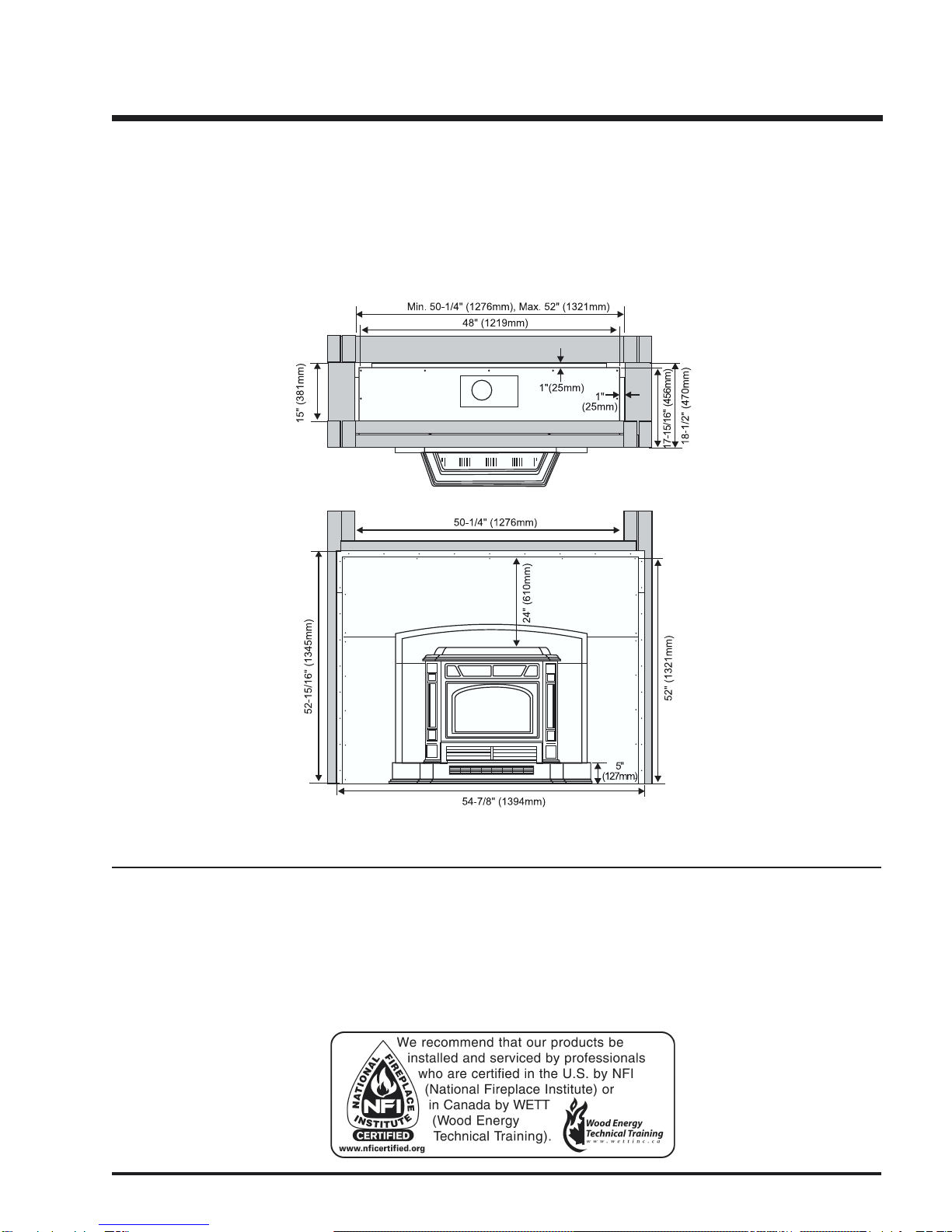
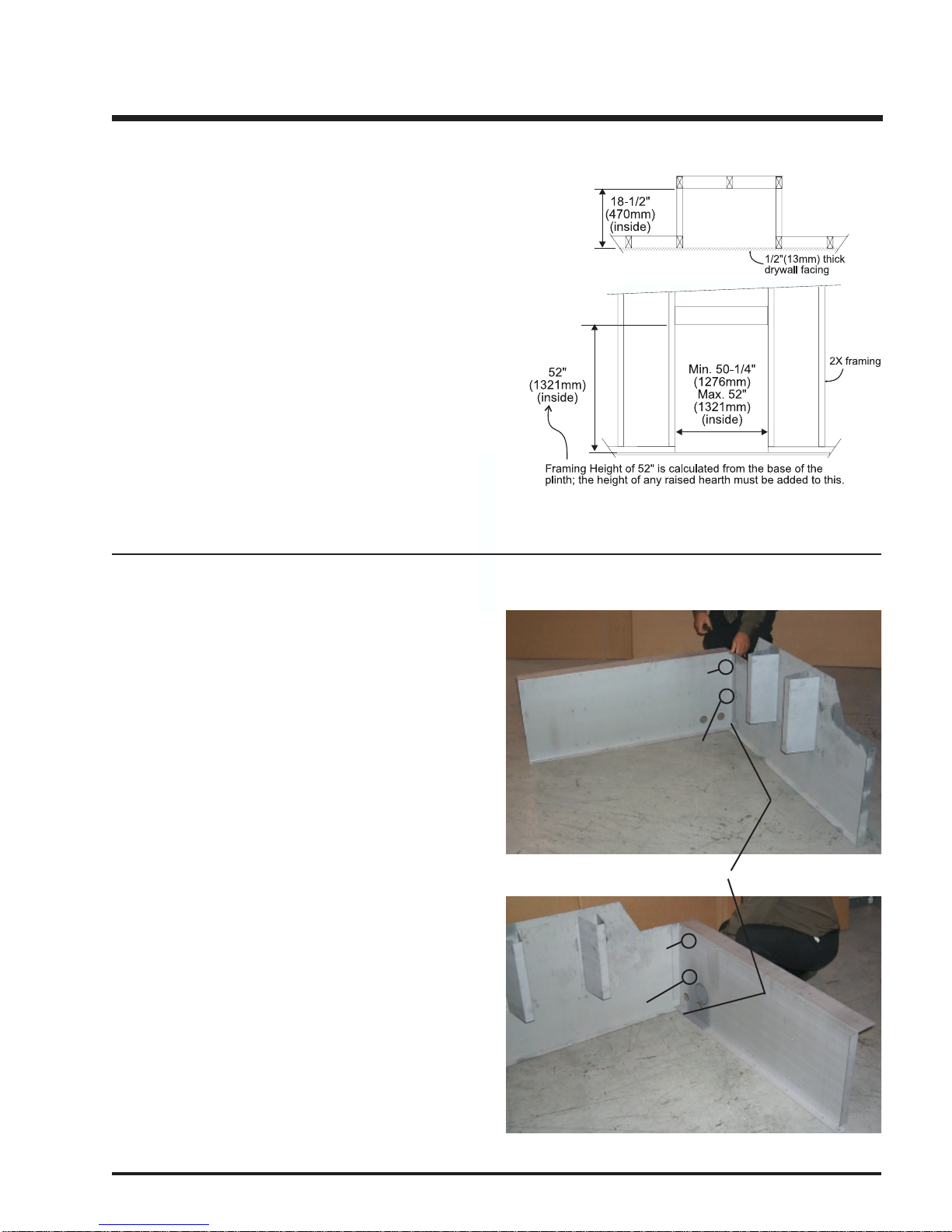
The clearances for the Zero Clearance Kit are 0" to combustibles (back, side and floor) but when planning your installation
review the clearances required for the Insert (see below) after it is installed in the Zero Clearance Kit.
Warning: Combustible facing materials must not extend inside the 1/2" (13mm) lip at the edge of the face panels.
Any non-combustible facing materials (such as ceramic tile or masonry face brick) up to 1-1/2" (38mm) thick may be used
to finish the area inside the 1/2" (13mm) lip on the face panels. Non-combustible tile backer board such as Wonderboard or
Durock , or metal lath or screen may be fastened directly to the front of the face panels to provide a base for attaching facing
materials if needed. The Zero Clearance Kit must be installed on a flat, solid, continuous surface (e.g. wood, metal, concrete).
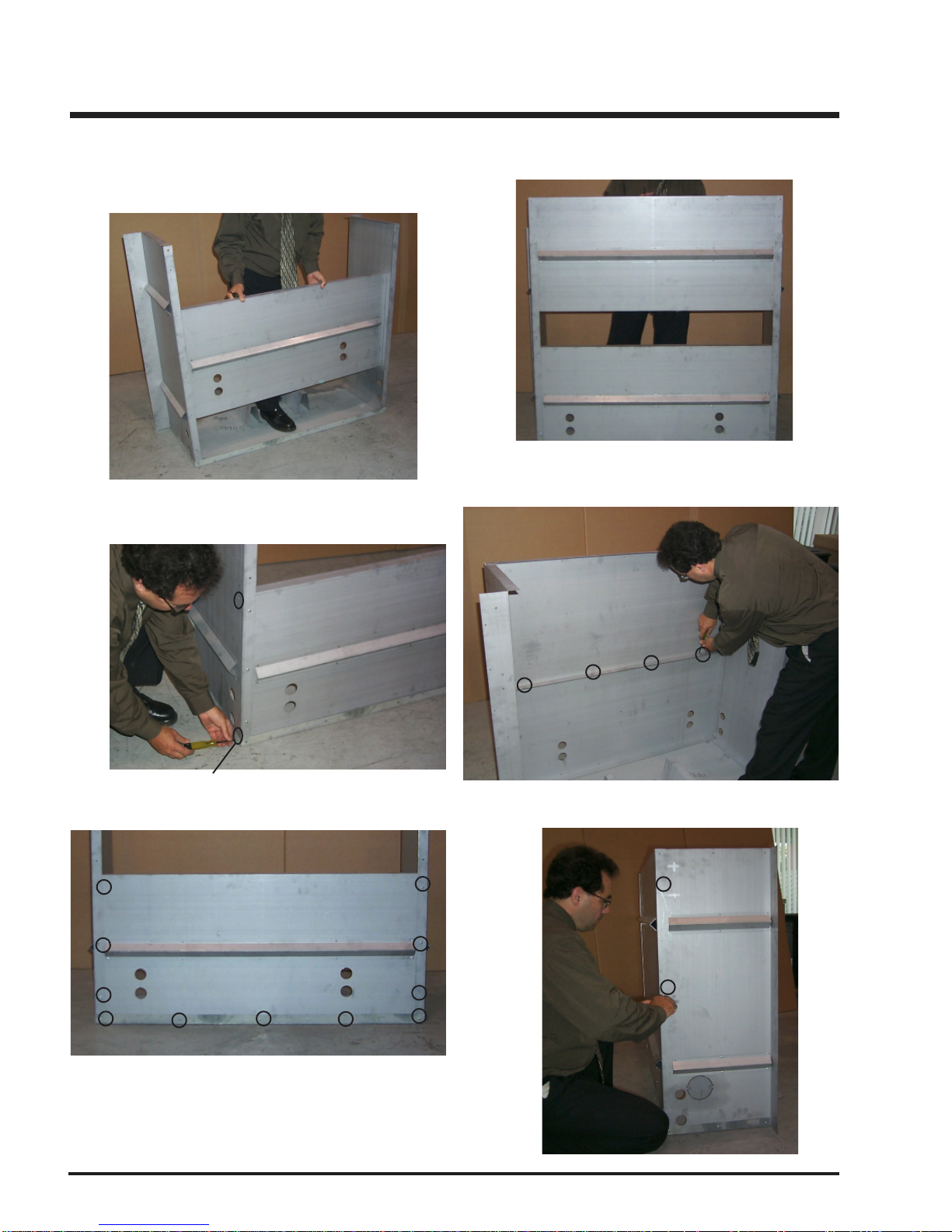
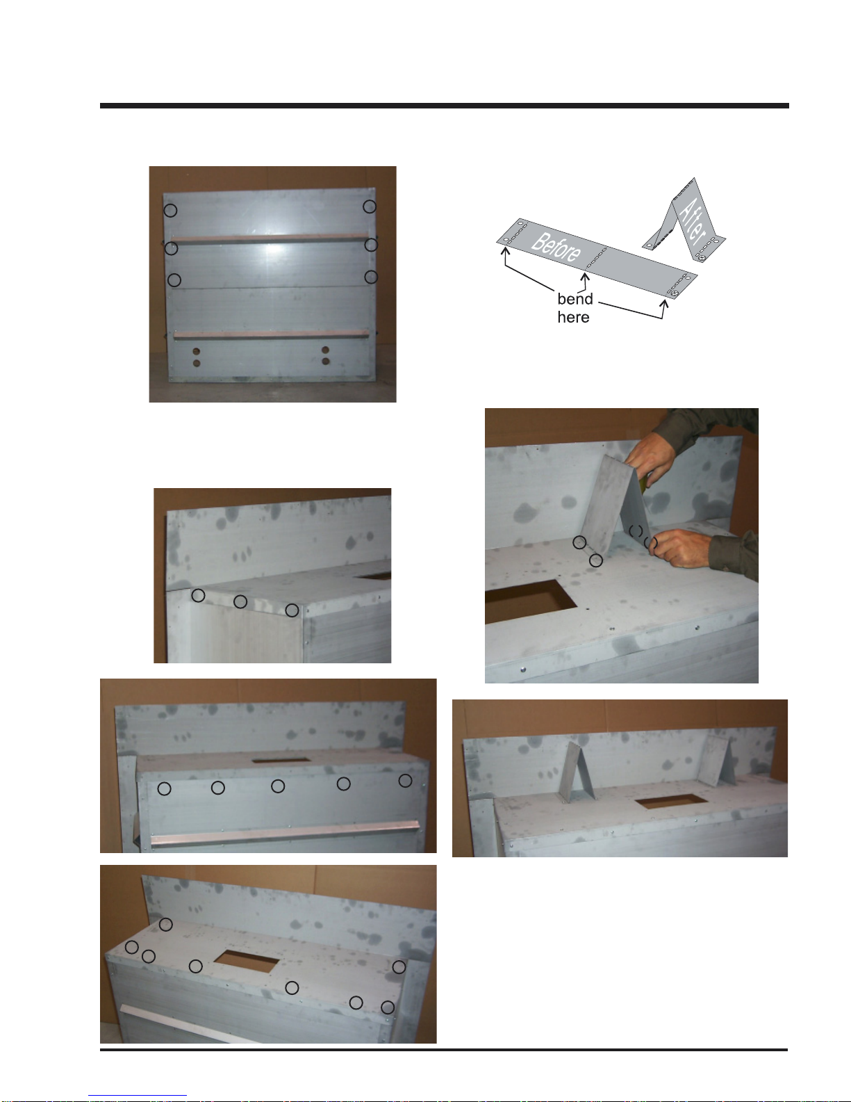
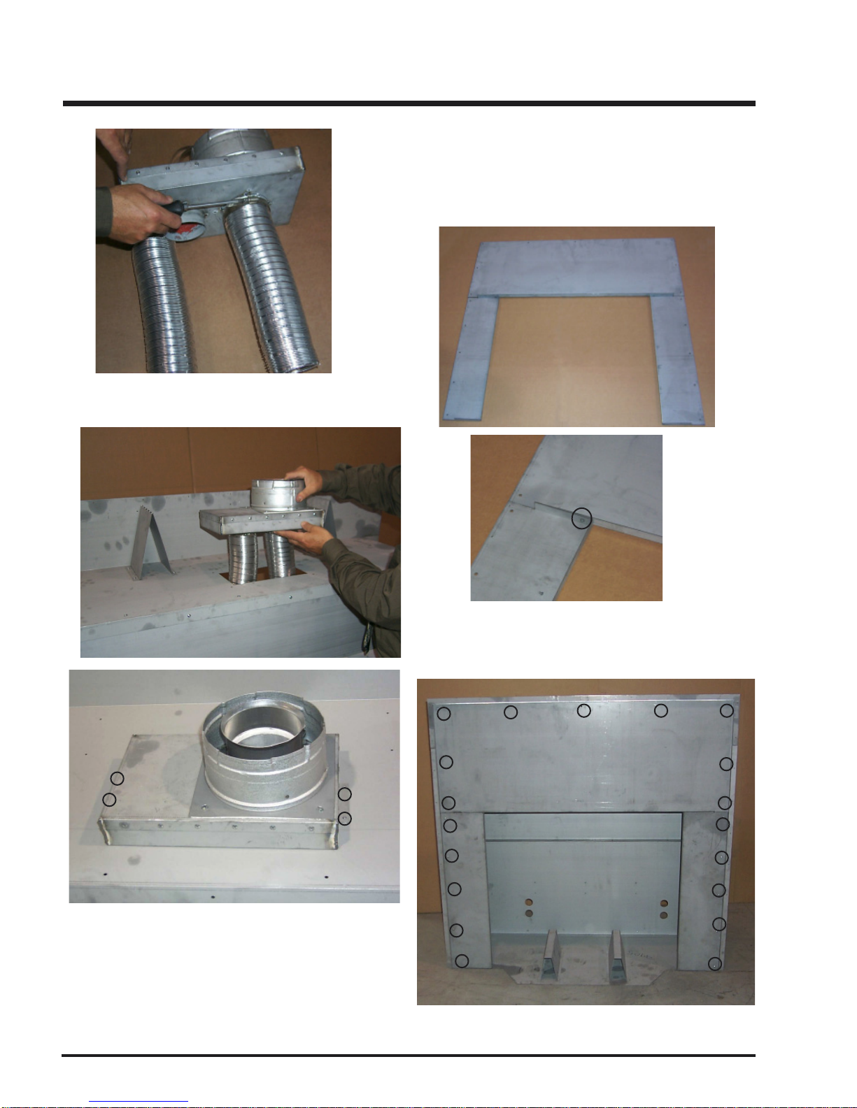
INSTALLATION
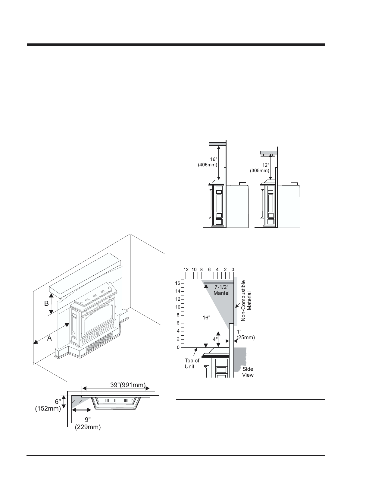
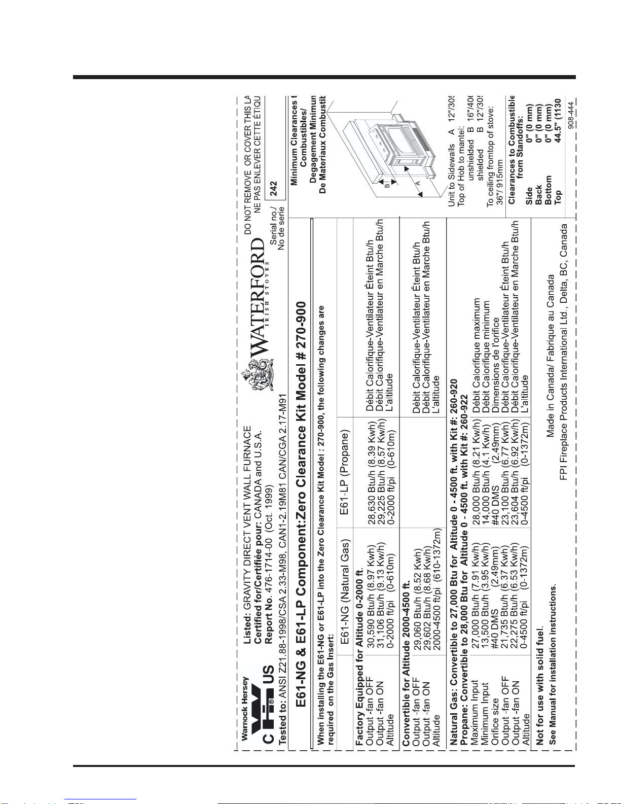
Emerald Insert Clearances to Combustibles:
From Unit
Sides A 12" / 305 mm
Unit to Unprotected Mantel B 16" / 406 mm
(see Mantel clearance diagram below)
Unit to Protected Mantel* C 12" / 305mm
In addition to these clearances, adequate accessibility
clearance for servicing and proper operation must be main-
tained.
Do not in any way obstruct the combustion air inlets that are
located on the front of the heater.
Floor Protection
If the appliance is installed in a fireplace that is elevated 5"
(127mm) or higher (i.e., a Waterford Zero Clearance Cabinet,
zero clearance fireplace, brick plinth, etc.), no floor protection is
required in front of the appliance.
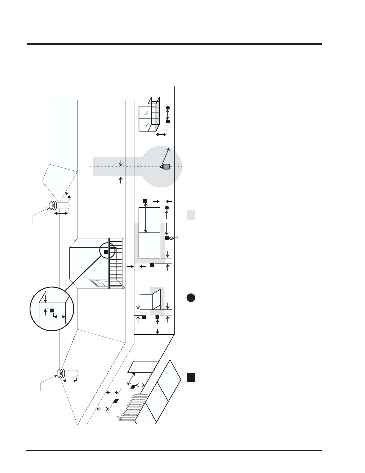
Clearance from top of hob to
mantel and combustible trim,
unshielded.
Clearance from top of hob to
manteland combustible trim,
shielded.
*Mantel shield must have a
1" (25mm) air space be-
tween the mantel and shield
and a 1" (25mm) gap be-
tweenonthebackoftheshield
and the facing.
Combustibles are permitted within
the shaded area.
Combustibles are permitted within
the shaded area, on either side.