Introduction
This section contains operation and maintenance instructions for Waterous
K, KC, T, TK and TA series gear drive transmissions. The term “series” used
here refers to related transmissions or a basic type of transmission used with
several types of pumps. The T, TA series transmission, for instance, has two
basic gear sizes and several different bellhousings and drive shafts available
for the various pump and engine sizes, yet all of the same basic construction.
Although the transmissions differ in detail, they are all similar in general de-
sign.
The information in this section applies to the transmission and related equip-
ment only. Refer to the pump instructions for data on the rest of the main
pump, and to the accessory instructions for information on the pump acces-
sories.
For E301-A and E302-A motor pump models, refer to instructions for T series
transmissions.
General Description for K, T, TK & TA Series Transmissions
Each series is available with different shafts and gears for medium and heavy
duty applications. The medium duty transmission is normally used for the
smaller, high speed pumps rated 500 gpm or less, while the heavy duty trans-
mission is intended mainly for larger, slower pumps rated at 500 gpm through
1250 gpm. An extra heavy duty K series transmission is available for pumps
rated above 1250 gpm.
The two helical gears in each transmission are properly sized to provide an
adequate safety factor. Ball bearings are used throughout each transmission.
Several gear ratios are available to permit closely matching the impeller shaft
speed and power requirements to individual engine performance. The vari-
ous transmissions are described in greater detail below:
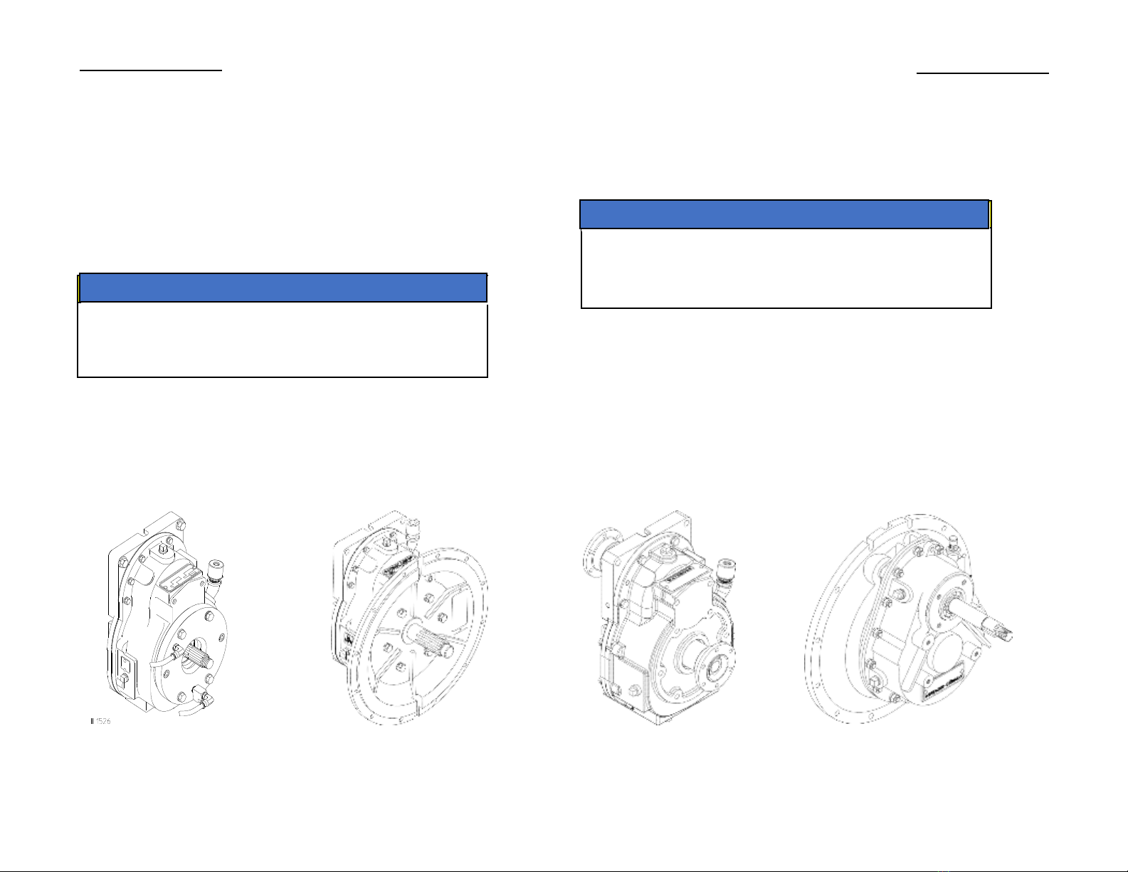
K Series Transmission
This transmission is designed primarily to be driven by a power take-off or
power divider. The medium-duty case has a 1-1/8 in. straight keyed shaft
while the heavy duty case has a 1-3/8 in. 10 spline shaft, and the extra heavy
duty case has a 1-1/2 in. 10 spline shaft.
TK Series Power Take-Off
This PTO allows the rear mounting of a fire pump. TK PTO is identical to the
K-series, except that it has companion flanges on the drive and driven shafts.
T, TA Series Transmission
This case is identical to the K series, except that it includes a bell housing
flange and the proper drive shaft for direct mounting on an engine bell hous-
ing.
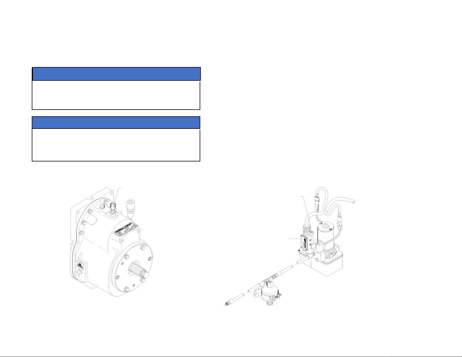
Mechanical Tachometer Drive
A tachometer drive is available as an option for the K and T series transmis-
sions. This accessory includes a drive gear and a driven gear with extension
which operates at half the input shaft speed. The driven gear extension pro-
trudes from its housing at a 15 degree angle from horizontal.